
User Guide
Page 3
... as the processors, memory DIMMs, and other components. Preface About this Manual Thank you for installing or replacing components such as update the compute module firmware using the Intel® Compute Module MFS5520VI. Chapter 4 provides information to update the compute module BIOS. It provides step-bystep instructions and diagrams for purchasing and using the Intel® Modular Server Control UI and...
... as the processors, memory DIMMs, and other components. Preface About this Manual Thank you for installing or replacing components such as update the compute module firmware using the Intel® Compute Module MFS5520VI. Chapter 4 provides information to update the compute module BIOS. It provides step-bystep instructions and diagrams for purchasing and using the Intel® Modular Server Control UI and...
User Guide
Page 7
... Installing an Intel® Compute Module MFS5520VI 13 Removing a Compute Module from the Chassis 13 Installing a Compute Module into the Chassis 14 Removing or Installing the Top Cover 14 Removing the Top Cover ...14 Installing the Top Cover ...16 Installing or Replacing a Processor 17 Installing a Processor ...17 Replacing a Processor ...25 Installing and Removing Memory Modules 33 Supported Memory ...33 Memory Map and...
... Installing an Intel® Compute Module MFS5520VI 13 Removing a Compute Module from the Chassis 13 Installing a Compute Module into the Chassis 14 Removing or Installing the Top Cover 14 Removing the Top Cover ...14 Installing the Top Cover ...16 Installing or Replacing a Processor 17 Installing a Processor ...17 Replacing a Processor ...25 Installing and Removing Memory Modules 33 Supported Memory ...33 Memory Map and...

User Guide
Page 12
... 64 Figure 48. Advanced Mass Storage Controller Configuration Screen 67 Figure 50. Server Management - Console Redirection Enabled Screen 79 Figure 57. Exit Screen ...86 Figure 62. BIOS Recover Jumper 94 xii Intel® Compute Module MFS5520VI User Guide Setup Layout...54 Figure 44. Memory RAS and Performance Configuration Screen 66 Figure 49. Advanced PCI Configuration Screen...
... 64 Figure 48. Advanced Mass Storage Controller Configuration Screen 67 Figure 50. Server Management - Console Redirection Enabled Screen 79 Figure 57. Exit Screen ...86 Figure 62. BIOS Recover Jumper 94 xii Intel® Compute Module MFS5520VI User Guide Setup Layout...54 Figure 44. Memory RAS and Performance Configuration Screen 66 Figure 49. Advanced PCI Configuration Screen...

User Guide
Page 13
... Options Details 83 Table 14. Keyboard Commands 55 Table 5. Advanced Memory Configuration Screen Details 65 Table 8. Server Management Screen Details 77 Table 12. Compute Module Features 3 Table 2. Main Screen Details 59 Table 6. Advanced PCI Configuration Details 72 Table 10. Exit Screen Details 86 Intel® Compute Module MFS5520VI User Guide xiii Configuration Jumper Description 6 Table 3. Diagnostic LED Information...
... Options Details 83 Table 14. Keyboard Commands 55 Table 5. Advanced Memory Configuration Screen Details 65 Table 8. Server Management Screen Details 77 Table 12. Compute Module Features 3 Table 2. Main Screen Details 59 Table 6. Advanced PCI Configuration Details 72 Table 10. Exit Screen Details 86 Intel® Compute Module MFS5520VI User Guide xiii Configuration Jumper Description 6 Table 3. Diagnostic LED Information...
User Guide
Page 17
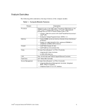
... summarizes the major features of the compute module. Compute Module Features Feature Processor Memory Chipset Video LAN Hard Drive Server Management Description Support for one or two Intel® Xeon® Processors 5500 Series or two Intel® Xeon® Processor 5600 Series...Memory One 10/100/1000 Intel® 82575 Gigabit Ethernet Controller LSI* 1064e SAS Controller On-board ServerEngines* LLC Pilot II Controller • Integrated Baseboard Management Controller (Integrated BMC), IPMI 2.0 compliant • Integrated Super I/O on LPC interface Intel® Compute Module MFS5520VI ...
... summarizes the major features of the compute module. Compute Module Features Feature Processor Memory Chipset Video LAN Hard Drive Server Management Description Support for one or two Intel® Xeon® Processors 5500 Series or two Intel® Xeon® Processor 5600 Series...Memory One 10/100/1000 Intel® 82575 Gigabit Ethernet Controller LSI* 1064e SAS Controller On-board ServerEngines* LLC Pilot II Controller • Integrated Baseboard Management Controller (Integrated BMC), IPMI 2.0 compliant • Integrated Super I/O on LPC interface Intel® Compute Module MFS5520VI ...
User Guide
Page 22
...-2 LEDs I /O mezzanine card Green Green Indicator Use the Intel® Modular Server Control software to 95-W Thermal Design Power (TDP): • 4.8 GT/s, 5.86 GT/s and 6.4 GT/s Intel® QuickPath Interconnect (Intel® QPI) • Enterprise Voltage Regulator-Down (EVRD) 11.1 Memory The Intel® Compute Module MFS5520VI supports six DDR3 memory channnels (three per processor socket) with dual-processor sockets...
...-2 LEDs I /O mezzanine card Green Green Indicator Use the Intel® Modular Server Control software to 95-W Thermal Design Power (TDP): • 4.8 GT/s, 5.86 GT/s and 6.4 GT/s Intel® QuickPath Interconnect (Intel® QPI) • Enterprise Voltage Regulator-Down (EVRD) 11.1 Memory The Intel® Compute Module MFS5520VI supports six DDR3 memory channnels (three per processor socket) with dual-processor sockets...

User Guide
Page 28
...and ESD information at the beginning of the compute module. do not attempt to ensure proper chassis cooling. Close the retention lever handles on a flat, non-conductive surface, with the cover side up. 14 Intel® Compute Module MFS5520VI User Guide This step is required to maintain ...proper airflow patterns throughout the chassis and to insert a compute module into an open position. 4. If you have not done so already, install any necessary options, such as processors, memory, hard drives ...
...and ESD information at the beginning of the compute module. do not attempt to ensure proper chassis cooling. Close the retention lever handles on a flat, non-conductive surface, with the cover side up. 14 Intel® Compute Module MFS5520VI User Guide This step is required to maintain ...proper airflow patterns throughout the chassis and to insert a compute module into an open position. 4. If you have not done so already, install any necessary options, such as processors, memory, hard drives ...

User Guide
Page 47
... channel level. Two modes are identified as Channel A, B, and C. DIMMs must be observed when selecting and configuring memory to remote memory. • The memory operational mode is the first DIMM slot on Channel A on the Intel® Compute Module MFS5520VI is detailed in the following general rules must be populated in Channel D through Channel C is not supported...
... channel level. Two modes are identified as Channel A, B, and C. DIMMs must be observed when selecting and configuring memory to remote memory. • The memory operational mode is the first DIMM slot on Channel A on the Intel® Compute Module MFS5520VI is detailed in the following general rules must be populated in Channel D through Channel C is not supported...

User Guide
Page 48
... DIMM_D1. Similarly, the memory in Channels A and B of each processor socket is DIMM_A1, DIMM_B1, DIMM_D1, and DIMM_E1 with both processor sockets, then a given RAS mode is selected only if both processor sockets populated. If Mirrored Channel mode is selected and the third channel of each processor socket. 34 Intel® Compute Module MFS5520VI User Guide
... DIMM_D1. Similarly, the memory in Channels A and B of each processor socket is DIMM_A1, DIMM_B1, DIMM_D1, and DIMM_E1 with both processor sockets, then a given RAS mode is selected only if both processor sockets populated. If Mirrored Channel mode is selected and the third channel of each processor socket. 34 Intel® Compute Module MFS5520VI User Guide
User Guide
Page 67
...is displayed by manually pressing the compute module power button. 3. When the BIOS Setup Utility is entered, the Main screen is sectioned into functional areas. Intel® Compute Module MFS5520VI User Guide 53 Refer to clear the CMOS memory. Press the function key when ...to the Intel® Modular Server System MFSYS25/MFSYS35 User Guide for the Intel® Compute Module MFS5520VI's built-in devices, boot manager, and error manager. Press to enter SETUP The message above is displayed after POST completes the memory test either the Intel® Modular Server Control UI...
...is displayed by manually pressing the compute module power button. 3. When the BIOS Setup Utility is entered, the Main screen is sectioned into functional areas. Intel® Compute Module MFS5520VI User Guide 53 Refer to clear the CMOS memory. Press the function key when ...to the Intel® Modular Server System MFSYS25/MFSYS35 User Guide for the Intel® Compute Module MFS5520VI's built-in devices, boot manager, and error manager. Press to enter SETUP The message above is displayed after POST completes the memory test either the Intel® Modular Server Control UI...

User Guide
Page 73
... go to select the next field. Hours are not affected by this setting. Intel® Compute Module MFS5520VI User Guide 59 Table 5. Displays the total physical memory installed in the compute module, in as Platform ID System BIOS Version System BIOS Build Date Total Memory Quiet Boot POST Error Pause System Date System Time Options Description Enabled Disabled...
... go to select the next field. Hours are not affected by this setting. Intel® Compute Module MFS5520VI User Guide 59 Table 5. Displays the total physical memory installed in the compute module, in as Platform ID System BIOS Version System BIOS Build Date Total Memory Quiet Boot POST Error Pause System Date System Time Options Description Enabled Disabled...

User Guide
Page 77
...pairs (even line + odd line). [Disabled] - This screen also provides a link to configure memory RAS (Reliability, Availability, and Serviceability) and view memory performance information and settings. Enable/Disable Intel® Virtualization Technology for Directed I /O. Cache lines are fetched in independent partitions. NOTE: Modifying this... classes of this screen from the Advanced menu. Only the current cache line required is fetched. Intel® Compute Module MFS5520VI User Guide 63 Contact your OS vendor regarding OS support of malicious buffer overflow attacks.
...pairs (even line + odd line). [Disabled] - This screen also provides a link to configure memory RAS (Reliability, Availability, and Serviceability) and view memory performance information and settings. Enable/Disable Intel® Virtualization Technology for Directed I /O. Cache lines are fetched in independent partitions. NOTE: Modifying this... classes of this screen from the Advanced menu. Only the current cache line required is fetched. Intel® Compute Module MFS5520VI User Guide 63 Contact your OS vendor regarding OS support of malicious buffer overflow attacks.

User Guide
Page 78
Advanced Memory Configuration Screen 64 Intel® Compute Module MFS5520VI User Guide . Figure 47.
Advanced Memory Configuration Screen 64 Intel® Compute Module MFS5520VI User Guide . Figure 47.

User Guide
Page 79
... and settings. Each DIMM socket field reflects one of memory mirroring. Intel® Compute Module MFS5520VI User Guide 65 Information only. Information only. Displays the state of MB or GB. Memory RAS and Performance Configuration The Memory RAS (Reliability, Availability, and Serviceability) and Performance Configuration screen displays current memory performance information and settings. Under capabilities, this slot is...
... and settings. Each DIMM socket field reflects one of memory mirroring. Intel® Compute Module MFS5520VI User Guide 65 Information only. Information only. Displays the state of MB or GB. Memory RAS and Performance Configuration The Memory RAS (Reliability, Availability, and Serviceability) and Performance Configuration screen displays current memory performance information and settings. Under capabilities, this slot is...

User Guide
Page 80
...Figure 48. By default, the SAS controller is set to [Disabled], the compute module will not be able to [Enabled]. If the SAS controller is selected then select Memory Configuration. Memory RAS and Performance Configuration Screen Mass Storage Controller Configuration The Mass Storage Controller ...access the system storage. This enables the compute module to enable or disable the SAS controller. To access this screen from the Main screen press the right arrow key until the Advanced menu is set to access storage. 66 Intel® Compute Module MFS5520VI User Guide
...Figure 48. By default, the SAS controller is set to [Disabled], the compute module will not be able to [Enabled]. If the SAS controller is selected then select Memory Configuration. Memory RAS and Performance Configuration Screen Mass Storage Controller Configuration The Mass Storage Controller ...access the system storage. This enables the compute module to enable or disable the SAS controller. To access this screen from the Main screen press the right arrow key until the Advanced menu is set to access storage. 66 Intel® Compute Module MFS5520VI User Guide

User Guide
Page 84
...memory usage and on and accessible by the OS. If auto is selected, Legacy USB support is enabled if a USB device is enabled. Exclude USB in Boot Table. When enabled, all onboard USB controllers are grayed out. When enabled on-board USB ports are turned on -board NIC controllers. 70 Intel® Compute Module MFS5520VI... regarding OS support of the Advanced USB Configuration screen Table 8. USB device boot support and PS/2 emulation for the compute module. The following table describes the features of this will remove all USB Mass Storage devices as Boot options. By default...
...memory usage and on and accessible by the OS. If auto is selected, Legacy USB support is enabled if a USB device is enabled. Exclude USB in Boot Table. When enabled, all onboard USB controllers are grayed out. When enabled on-board USB ports are turned on -board NIC controllers. 70 Intel® Compute Module MFS5520VI... regarding OS support of the Advanced USB Configuration screen Table 8. USB device boot support and PS/2 emulation for the compute module. The following table describes the features of this will remove all USB Mass Storage devices as Boot options. By default...

User Guide
Page 86
... 4 GB or greater address space. Advanced PCI Configuration Details Setup Item Maximize Memory below 4 GB for Static Closed Loop Thermal Throttling (CLTT) as long as the installed DIMMs have Module Thermal Sensors. Load the embedded option ROM for the Intel® Compute Module MFS5520VI. Auto Throttling mode • [CLTT] - To access this field is selected, NIC2...
... 4 GB or greater address space. Advanced PCI Configuration Details Setup Item Maximize Memory below 4 GB for Static Closed Loop Thermal Throttling (CLTT) as long as the installed DIMMs have Module Thermal Sensors. Load the embedded option ROM for the Intel® Compute Module MFS5520VI. Auto Throttling mode • [CLTT] - To access this field is selected, NIC2...

User Guide
Page 109
... gracefully and restart the compute module to clear the memory and reload the operating system. • Cold boot reset: Turn the compute module power button off and then turn it back on the server board correct? • Are the configuration settings defined in the Intel® Modular Server System MFSYS25/MFSYS35 and Intel® Compute Module MFS5000SI/MFS5520VI Tested Hardware and Operating...
... gracefully and restart the compute module to clear the memory and reload the operating system. • Cold boot reset: Turn the compute module power button off and then turn it back on the server board correct? • Are the configuration settings defined in the Intel® Modular Server System MFSYS25/MFSYS35 and Intel® Compute Module MFS5000SI/MFS5520VI Tested Hardware and Operating...

User Guide
Page 111
Characters are Distorted or Incorrect Check the following : Intel® Compute Module MFS5520VI User Guide 97 No Available Storage Check the following : • Is the video monitor properly adjusted? If so, the power LED might be defective. ...Num Lock light is turned on and functioning properly. • Verify that the installed memory has been populated according to the troubleshooting section of the Intel® Modular Server System MFSYS25/MFSYS35 User Guide for use in the compute module. • Verify that the brightness and contrast controls on -board video controller enabled in...
Characters are Distorted or Incorrect Check the following : Intel® Compute Module MFS5520VI User Guide 97 No Available Storage Check the following : • Is the video monitor properly adjusted? If so, the power LED might be defective. ...Num Lock light is turned on and functioning properly. • Verify that the installed memory has been populated according to the troubleshooting section of the Intel® Modular Server System MFSYS25/MFSYS35 User Guide for use in the compute module. • Verify that the brightness and contrast controls on -board video controller enabled in...