
User Guide
Page 1
Intel® Compute Module MFS5520VI User Guide A Guide for Technically Qualified Assemblers of Intel® Identified Subassemblies/ Products Intel Order Number E60459-006
Intel® Compute Module MFS5520VI User Guide A Guide for Technically Qualified Assemblers of Intel® Identified Subassemblies/ Products Intel Order Number E60459-006

User Guide
Page 3
... Setup Utility and how to assist you identify components and their locations. This includes a list of the compute module features, illustrations of this manual,see http:// www.intel.com/support/motherboards/server/MFS5520VI/. Chapter 4 provides information to update the compute module BIOS. Manual Organization Chapter 1 provides a brief overview of this manual provides technical specifications, regulatory information,"getting...
... Setup Utility and how to assist you identify components and their locations. This includes a list of the compute module features, illustrations of this manual,see http:// www.intel.com/support/motherboards/server/MFS5520VI/. Chapter 4 provides information to update the compute module BIOS. Manual Organization Chapter 1 provides a brief overview of this manual provides technical specifications, regulatory information,"getting...

User Guide
Page 5
... Dokument, bevor Sie eine der Anweisungen ausführen. Consultez Intel® Server Boards and Server Chassis Safety Information sur le site http://support.intel.com/support/motherboards/server/sb/cs-010770.htm. und Sicherheitshinweise in this document before performing any of the instructions. Intel® Compute Module MFS5520VI User Guide v Consignes de sécurité Lisez attention toutes...
... Dokument, bevor Sie eine der Anweisungen ausführen. Consultez Intel® Server Boards and Server Chassis Safety Information sur le site http://support.intel.com/support/motherboards/server/sb/cs-010770.htm. und Sicherheitshinweise in this document before performing any of the instructions. Intel® Compute Module MFS5520VI User Guide v Consignes de sécurité Lisez attention toutes...
User Guide
Page 6
...: To protect internal components and for proper cooling and airflow, the compute module should maintain or configure the chassis. vi Intel® Compute Module MFS5520VI User Guide Turn off only DC power to the compute module; We recommend that you may be present on the board. If ... communication cables. Otherwise, personal injury or equipment damage can damage the contacts inside the chassis. If your server product, whether you remove the compute module enclosure cover to access components inside the jumper, causing intermittent problems with your jumpers do not have a...
...: To protect internal components and for proper cooling and airflow, the compute module should maintain or configure the chassis. vi Intel® Compute Module MFS5520VI User Guide Turn off only DC power to the compute module; We recommend that you may be present on the board. If ... communication cables. Otherwise, personal injury or equipment damage can damage the contacts inside the chassis. If your server product, whether you remove the compute module enclosure cover to access components inside the jumper, causing intermittent problems with your jumpers do not have a...
User Guide
Page 7
...You Begin ...13 Tools and Supplies Needed ...13 Installation Guidelines ...13 Removing and Installing an Intel® Compute Module MFS5520VI 13 Removing a Compute Module from the Chassis 13 Installing a Compute Module into the Chassis 14 Removing or Installing the Top Cover 14 Removing the Top Cover ...14 ... or Replacing a Processor 17 Installing a Processor ...17 Replacing a Processor ...25 Installing and Removing Memory Modules 33 Supported Memory ...33 Memory Map and Population Rules 33 Installing DIMMs ...35 Removing DIMMs ...38 Intel® Compute Module MFS5520VI User Guide vii
...You Begin ...13 Tools and Supplies Needed ...13 Installation Guidelines ...13 Removing and Installing an Intel® Compute Module MFS5520VI 13 Removing a Compute Module from the Chassis 13 Installing a Compute Module into the Chassis 14 Removing or Installing the Top Cover 14 Removing the Top Cover ...14 ... or Replacing a Processor 17 Installing a Processor ...17 Replacing a Processor ...25 Installing and Removing Memory Modules 33 Supported Memory ...33 Memory Map and Population Rules 33 Installing DIMMs ...35 Removing DIMMs ...38 Intel® Compute Module MFS5520VI User Guide vii
User Guide
Page 8
... Setup 53 General Layout and Navigation 53 Setup Menus ...57 Main ...58 Advanced ...60 Security ...73 Server Management ...76 Boot Options ...81 Boot Manager ...84 Error Manager ...85 Exit ...86 Upgrading the BIOS...Display ...97 Characters are Distorted or Incorrect 97 No Available Storage ...97 Cannot Connect to a Compute Module 98 Problems with Newly Installed Application Software 98 Problems with Application Software that Previously Functioned Properly 99... Japan ...102 Latin America ...102 B Product Regulatory Requirements 105 viii Intel® Compute Module MFS5520VI User Guide
... Setup 53 General Layout and Navigation 53 Setup Menus ...57 Main ...58 Advanced ...60 Security ...73 Server Management ...76 Boot Options ...81 Boot Manager ...84 Error Manager ...85 Exit ...86 Upgrading the BIOS...Display ...97 Characters are Distorted or Incorrect 97 No Available Storage ...97 Cannot Connect to a Compute Module 98 Problems with Newly Installed Application Software 98 Problems with Application Software that Previously Functioned Properly 99... Japan ...102 Latin America ...102 B Product Regulatory Requirements 105 viii Intel® Compute Module MFS5520VI User Guide

User Guide
Page 10
D Installation/Assembly Safety Instructions 131 English ...131 Deutsch ...133 Français ...136 Español ...138 Italiano ...140 x Intel® Compute Module MFS5520VI User Guide
D Installation/Assembly Safety Instructions 131 English ...131 Deutsch ...133 Français ...136 Español ...138 Italiano ...140 x Intel® Compute Module MFS5520VI User Guide
User Guide
Page 11
... 23 Figure 17. Removing the Heatsink 26 Figure 20. DIMM Slot Order ...35 Figure 30. Removing Processor Air Duct 39 Figure 34. Intel® Compute Module MFS5520VI 1 Figure 2. Component and Connector Locations 4 Figure 4. Installing Top Cover 16 Figure 8. Removing Protective Shipping Cover 29 Figure 24. Installing...Orienting and Installing Processor 29 Figure 25. Removing Mezzanine Card 47 Figure 41. List of Figures Figure 1. Server Board ...2 Figure 3. Opening the Load Plate 20 Figure 12. Reinstalling Processor Air Duct 32 Figure 28. Removing Screws from...
... 23 Figure 17. Removing the Heatsink 26 Figure 20. DIMM Slot Order ...35 Figure 30. Removing Processor Air Duct 39 Figure 34. Intel® Compute Module MFS5520VI 1 Figure 2. Component and Connector Locations 4 Figure 4. Installing Top Cover 16 Figure 8. Removing Protective Shipping Cover 29 Figure 24. Installing...Orienting and Installing Processor 29 Figure 25. Removing Mezzanine Card 47 Figure 41. List of Figures Figure 1. Server Board ...2 Figure 3. Opening the Load Plate 20 Figure 12. Reinstalling Processor Air Duct 32 Figure 28. Removing Screws from...

User Guide
Page 12
Memory RAS and Performance Configuration Screen 66 Figure 49. Advanced PCI Configuration Screen 71 Figure 53. Server Management - Server Management - Error Manager Screen 85 Figure 61. Advanced Processor Configuration Screen 61 Figure 47. Advanced Serial Port ...and Performance Configuration Screen 73 Figure 54. Security Screen ...74 Figure 55. Server Management Screen 76 Figure 56. Boot Options Screen 82 Figure 59. Boot Manager Screen 84 Figure 60. Password Clear Jumper 90 Figure 63. BIOS Recover Jumper 94 xii Intel® Compute Module MFS5520VI User Guide
Memory RAS and Performance Configuration Screen 66 Figure 49. Advanced PCI Configuration Screen 71 Figure 53. Server Management - Server Management - Error Manager Screen 85 Figure 61. Advanced Processor Configuration Screen 61 Figure 47. Advanced Serial Port ...and Performance Configuration Screen 73 Figure 54. Security Screen ...74 Figure 55. Server Management Screen 76 Figure 56. Boot Options Screen 82 Figure 59. Boot Manager Screen 84 Figure 60. Password Clear Jumper 90 Figure 63. BIOS Recover Jumper 94 xii Intel® Compute Module MFS5520VI User Guide

User Guide
Page 13
... Processor Configuration Details 62 Table 7. Advanced PCI Configuration Details 72 Table 10. Keyboard Commands 55 Table 5. Compute Module Features 3 Table 2. Main Screen Details 59 Table 6. Configuration Jumper Description 6 Table 3. Server Management Console Redirection Details 80 Table 13. List of Tables Table 1. Exit Screen Details 86 Intel® Compute Module MFS5520VI User Guide xiii Diagnostic LED Information 7 Table 4.
... Processor Configuration Details 62 Table 7. Advanced PCI Configuration Details 72 Table 10. Keyboard Commands 55 Table 5. Compute Module Features 3 Table 2. Main Screen Details 59 Table 6. Configuration Jumper Description 6 Table 3. Server Management Console Redirection Details 80 Table 13. List of Tables Table 1. Exit Screen Details 86 Intel® Compute Module MFS5520VI User Guide xiii Diagnostic LED Information 7 Table 4.

User Guide
Page 15
Intel® Compute Module MFS5520VI AF003075 Intel® Compute Module MFS5520VI User Guide 1 1 Compute Module Features This chapter briefly describes the main features of the Intel® Compute Module MFS5520VI, as well as provides illustrations showing the location of important components and connections on the compute module. The Intel® Compute Module MFS5520VI is shown in the following pictures. 1 I/O 2 1 2 ID Figure 1.
Intel® Compute Module MFS5520VI AF003075 Intel® Compute Module MFS5520VI User Guide 1 1 Compute Module Features This chapter briefly describes the main features of the Intel® Compute Module MFS5520VI, as well as provides illustrations showing the location of important components and connections on the compute module. The Intel® Compute Module MFS5520VI is shown in the following pictures. 1 I/O 2 1 2 ID Figure 1.
User Guide
Page 17
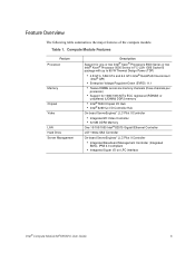
... summarizes the major features of the compute module. Compute Module Features Feature Processor Memory Chipset Video LAN Hard Drive Server Management Description Support for one or two Intel® Xeon® Processors 5500 Series or two Intel® Xeon® Processor 5600 ...10/100/1000 Intel® 82575 Gigabit Ethernet Controller LSI* 1064e SAS Controller On-board ServerEngines* LLC Pilot II Controller • Integrated Baseboard Management Controller (Integrated BMC), IPMI 2.0 compliant • Integrated Super I/O on LPC interface Intel® Compute Module MFS5520VI User Guide 3 ...
... summarizes the major features of the compute module. Compute Module Features Feature Processor Memory Chipset Video LAN Hard Drive Server Management Description Support for one or two Intel® Xeon® Processors 5500 Series or two Intel® Xeon® Processor 5600 ...10/100/1000 Intel® 82575 Gigabit Ethernet Controller LSI* 1064e SAS Controller On-board ServerEngines* LLC Pilot II Controller • Integrated Baseboard Management Controller (Integrated BMC), IPMI 2.0 compliant • Integrated Super I/O on LPC interface Intel® Compute Module MFS5520VI User Guide 3 ...

User Guide
Page 18
Component and Connector Locations 4 Intel® Compute Module MFS5520VI User Guide Connector and Component Locations E D C B A F G H I Q PO J N M M L K AF003077 A Intel® 5520 Chipset I/O Hub B CPU2 DIMM Slots C Mezzanine Card Connector 1 D CPU 1 with Heatsink E Mezzanine Card Connector 2 F Midplane Power Connector G Midplane Signal Connector H Midplane Guide Pin Receptacle I CPU 1 DIMM Slots J CPU 2 Socket K Power/Fault LEDs L Power Switch M Activity and ID LEDs N Video Connector O USB Ports 2 and 3 P USB Ports 0 and 1 Q CMOS Battery Figure 3.
Component and Connector Locations 4 Intel® Compute Module MFS5520VI User Guide Connector and Component Locations E D C B A F G H I Q PO J N M M L K AF003077 A Intel® 5520 Chipset I/O Hub B CPU2 DIMM Slots C Mezzanine Card Connector 1 D CPU 1 with Heatsink E Mezzanine Card Connector 2 F Midplane Power Connector G Midplane Signal Connector H Midplane Guide Pin Receptacle I CPU 1 DIMM Slots J CPU 2 Socket K Power/Fault LEDs L Power Switch M Activity and ID LEDs N Video Connector O USB Ports 2 and 3 P USB Ports 0 and 1 Q CMOS Battery Figure 3.
User Guide
Page 20
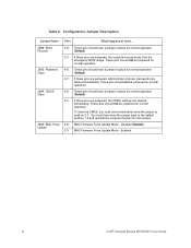
... operation. To clear the CMOS, you must then move the jumper to the default position 1-2 and reinstall the compute module into the chassis. Enabled 6 Intel® Compute Module MFS5520VI User Guide J9A3: Password Clear 1-2 These pins should have a jumper in place for normal operation (Default) 2-3... should have a jumper in place for normal operation. (Default) 2-3 If these pins are jumpered, the CMOS settings are jumpered, the compute module boots from the emergency BIOS image. J9A4: CMOS Clear 1-2 These pins should not be jumpered for normal operation. (Default) 2-3 If these...
... operation. To clear the CMOS, you must then move the jumper to the default position 1-2 and reinstall the compute module into the chassis. Enabled 6 Intel® Compute Module MFS5520VI User Guide J9A3: Password Clear 1-2 These pins should have a jumper in place for normal operation (Default) 2-3... should have a jumper in place for normal operation. (Default) 2-3 If these pins are jumpered, the CMOS settings are jumpered, the compute module boots from the emergency BIOS image. J9A4: CMOS Clear 1-2 These pins should not be jumpered for normal operation. (Default) 2-3 If these...

User Guide
Page 21
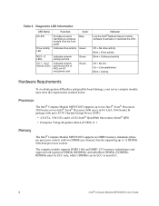
... blink = Non-critical Fast blink = Locate (when device does not have an ID LED) Double blink = Degraded state Intel® Compute Module MFS5520VI User Guide 7 Front Panel Connectors and Indicators Front Panel Indicators The Intel® Compute Module MFS5520VI includes a number of diagnostic LEDs on Slow Blink = Power is off On = Power on the front of each LED...
... blink = Non-critical Fast blink = Locate (when device does not have an ID LED) Double blink = Degraded state Intel® Compute Module MFS5520VI User Guide 7 Front Panel Connectors and Indicators Front Panel Indicators The Intel® Compute Module MFS5520VI includes a number of diagnostic LEDs on Slow Blink = Power is off On = Power on the front of each LED...
User Guide
Page 22
... link On = Link established Blink = Activity Hardware Requirements To avoid integration difficulties and possible board damage, your server compute module must be ECC only, while UDIMMs can be ECC or non-ECC. 8 Intel® Compute Module MFS5520VI User Guide The compute module supports DDR3 1066 and DDR3 1333 memory technologies and supports both registered DIMMs (RDIMMs) and unbuffered DIMMs...
... link On = Link established Blink = Activity Hardware Requirements To avoid integration difficulties and possible board damage, your server compute module must be ECC only, while UDIMMs can be ECC or non-ECC. 8 Intel® Compute Module MFS5520VI User Guide The compute module supports DDR3 1066 and DDR3 1333 memory technologies and supports both registered DIMMs (RDIMMs) and unbuffered DIMMs...

User Guide
Page 23
Power Supply A minimum of one compute module plus all other modules in the chassis. One power supply supports one 1000-Watt power supply is required to three compute modules (in any slot) plus all other modules in the chassis. Any additional power supplies above the minimum required (based on a compute module. Intel® Compute Module MFS5520VI User Guide 9 Two power supplies support two to turn on configuration) provide redundancy. Three power supplies support four to six compute modules (in any slot) plus all other modules in the chassis.
Power Supply A minimum of one compute module plus all other modules in the chassis. One power supply supports one 1000-Watt power supply is required to three compute modules (in any slot) plus all other modules in the chassis. Any additional power supplies above the minimum required (based on a compute module. Intel® Compute Module MFS5520VI User Guide 9 Two power supplies support two to turn on configuration) provide redundancy. Three power supplies support four to six compute modules (in any slot) plus all other modules in the chassis.
User Guide
Page 24
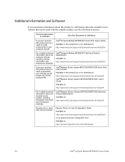
... need more information about this product and you need to assemble your compute module For in the product box or for download at: http://www.intel.com/support/motherboards/server/mfs5520vi/ Intel®Compute Module MFS5520VI Technical Product Specification Available at : http://serverconfigurator.intel.com/default.aspx 10 Intel® Compute Module MFS5520VI User Guide For this information or software Use this Document or...
... need more information about this product and you need to assemble your compute module For in the product box or for download at: http://www.intel.com/support/motherboards/server/mfs5520vi/ Intel®Compute Module MFS5520VI Technical Product Specification Available at : http://serverconfigurator.intel.com/default.aspx 10 Intel® Compute Module MFS5520VI User Guide For this information or software Use this Document or...
User Guide
Page 25
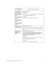
... to manage your Intel® Modular Server System Intel® Modular Server Control UI The Intel® Management Module integrated management interface for download at : http://www.intel.com/go/servermanagement/ Intel® Compute Module MFS5520VI User Guide 11 For software to the Intel® Modular Server System MFSYS25/MFSYS35 User Guide Available at: http://www.intel.com/support/motherboards/server/mfsys25/ Intel® System Management...
... to manage your Intel® Modular Server System Intel® Modular Server Control UI The Intel® Management Module integrated management interface for download at : http://www.intel.com/go/servermanagement/ Intel® Compute Module MFS5520VI User Guide 11 For software to the Intel® Modular Server System MFSYS25/MFSYS35 User Guide Available at: http://www.intel.com/support/motherboards/server/mfsys25/ Intel® System Management...

User Guide
Page 27
...server product, review the safety and ESD information at the beginning of this manual and in the appendices. 2. Observe the safety and ESD information at the beginning of this manual and in the appendices. 2. If the compute module is operating, shut down the operating system and turn off the compute module. 3. Intel® Compute Module MFS5520VI...the two lever handles. Removing and Installing an Intel® Compute Module MFS5520VI Removing a Compute Module from the Chassis To remove a compute module from the chassis. Remove the compute module from the chassis, follow these steps: 1. ...
...server product, review the safety and ESD information at the beginning of this manual and in the appendices. 2. Observe the safety and ESD information at the beginning of this manual and in the appendices. 2. If the compute module is operating, shut down the operating system and turn off the compute module. 3. Intel® Compute Module MFS5520VI...the two lever handles. Removing and Installing an Intel® Compute Module MFS5520VI Removing a Compute Module from the Chassis To remove a compute module from the chassis. Remove the compute module from the chassis, follow these steps: 1. ...