User Guide
Page 5
... Component Locations 3 Configuration Jumpers...4 Front Panel Connectors and Indicators 5 Hardware Requirements ...5 Processor ...5 Memory ...5 Power Supply ...6 Hardware Installations and Upgrades 7 Before You Begin ...7 Tools and Supplies Needed ...7 Installation Guidelines ...7 Removing and Installing an Intel® Compute Module MFS5000SI 7 Removing a Compute Module from the Server System 7 Installing a Compute Module into the Server System 8 Opening and Closing the Top Cover 8 Opening and Removing the...
... Component Locations 3 Configuration Jumpers...4 Front Panel Connectors and Indicators 5 Hardware Requirements ...5 Processor ...5 Memory ...5 Power Supply ...6 Hardware Installations and Upgrades 7 Before You Begin ...7 Tools and Supplies Needed ...7 Installation Guidelines ...7 Removing and Installing an Intel® Compute Module MFS5000SI 7 Removing a Compute Module from the Server System 7 Installing a Compute Module into the Server System 8 Opening and Closing the Top Cover 8 Opening and Removing the...
User Guide
Page 11
... Duct 29 Figure 33. Installing Standoffs for Mezzanine Card 33 Figure 37. Server Board ...1 Figure 3. Configuration Jumper Locations 4 Figure 5. Orienting and Installing Processor 13 Figure 13. Lowering Load Plate and Socket Lever 21 Figure 26. Installing DIMMs...27 Figure 31. Intel® Compute Module MFS5000SI 1 Figure 2. Front Panel Connectors and Indicators 5 Figure 6. Installing Top Cover 10...
... Duct 29 Figure 33. Installing Standoffs for Mezzanine Card 33 Figure 37. Server Board ...1 Figure 3. Configuration Jumper Locations 4 Figure 5. Orienting and Installing Processor 13 Figure 13. Lowering Load Plate and Socket Lever 21 Figure 26. Installing DIMMs...27 Figure 31. Intel® Compute Module MFS5000SI 1 Figure 2. Front Panel Connectors and Indicators 5 Figure 6. Installing Top Cover 10...
User Guide
Page 14
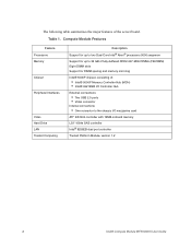
... Interfaces Video Hard Drive LAN Trusted Computing Description Support for up to two Dual-Core Intel® Xeon® processors 5000 sequence Support for up to the chassis I/O mezzanine card ATI* ES1000 controller with 16MB onboard memory LSI* 1064e SAS controller Intel® 8256EB dual port controller Trusted Platform Module, version 1.2 2 Intel® Compute Module MFS5000SI User Guide Table 1.
... Interfaces Video Hard Drive LAN Trusted Computing Description Support for up to two Dual-Core Intel® Xeon® processors 5000 sequence Support for up to the chassis I/O mezzanine card ATI* ES1000 controller with 16MB onboard memory LSI* 1064e SAS controller Intel® 8256EB dual port controller Trusted Platform Module, version 1.2 2 Intel® Compute Module MFS5000SI User Guide Table 1.
User Guide
Page 17
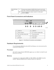
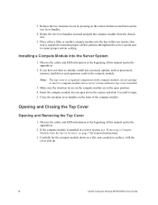
...(FB-DIMM) should not be installed. These pins should have a jumper in pairs, up to two Multi-Core Intel® Xeon® Processors 5xxx Series. These pins should be jumpered for normal system operation. (Default) Front Panel Connectors and Indicators ... Button J Power LED Figure 5. Intel® Compute Module MFS5000SI User Guide 5 Front Panel Connectors and Indicators Hardware Requirements To avoid integration difficulties and possible board damage, your system must be forced to eight total. Processor The Intel® Compute Module MFS5000SI supports up to boot from the...
...(FB-DIMM) should not be installed. These pins should have a jumper in pairs, up to two Multi-Core Intel® Xeon® Processors 5xxx Series. These pins should be jumpered for normal system operation. (Default) Front Panel Connectors and Indicators ... Button J Power LED Figure 5. Intel® Compute Module MFS5000SI User Guide 5 Front Panel Connectors and Indicators Hardware Requirements To avoid integration difficulties and possible board damage, your system must be forced to eight total. Processor The Intel® Compute Module MFS5000SI supports up to boot from the...
User Guide
Page 20
... cover side up. 8 Intel® Compute Module MFS5000SI User Guide If the compute module is installed in the compute module. Opening and Closing the Top Cover Opening and Removing the Top Cover 1. Installing a Compute Module into a server system without a top cover installed. 3. Carefully lay the compute module down on the front of the compute module; this step is a required component of the compute module. If you have...
... cover side up. 8 Intel® Compute Module MFS5000SI User Guide If the compute module is installed in the compute module. Opening and Closing the Top Cover Opening and Removing the Top Cover 1. Installing a Compute Module into a server system without a top cover installed. 3. Carefully lay the compute module down on the front of the compute module; this step is a required component of the compute module. If you have...
User Guide
Page 23
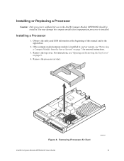
... Cover" on page 7 for use in the appendices. 2. For instructions, see "Removing a Compute Module from the Server System" on page 8. 4. Removing Processor Air Duct Intel® Compute Module MFS5000SI User Guide AF002404 11 Observe the safety and ESD information at the beginning of this manual and in the Intel® Compute Module MFS5000SI should be installed. Remove the top cover. Remove the...
... Cover" on page 7 for use in the appendices. 2. For instructions, see "Removing a Compute Module from the Server System" on page 8. 4. Removing Processor Air Duct Intel® Compute Module MFS5000SI User Guide AF002404 11 Observe the safety and ESD information at the beginning of this manual and in the Intel® Compute Module MFS5000SI should be installed. Remove the top cover. Remove the...
User Guide
Page 24
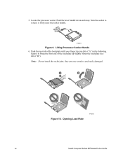
5. Lifting Processor Socket Handle 6. they are very sensitive and easily damaged. A B Figure 10. Opening Load Plate TP02075 12 Intel® Compute Module MFS5000SI User Guide Open the load plate (see letter "A" in the following figure) to release it. Locate the processor socket. Push the lever handle down and away from the socket to bring the front end of the load plate up slightly. Note: Do not touch the socket pins; Fully raise the socket handle. TP02074 Figure 9. Push the rear tab of the load plate with your finger tip (see letter "B").
5. Lifting Processor Socket Handle 6. they are very sensitive and easily damaged. A B Figure 10. Opening Load Plate TP02075 12 Intel® Compute Module MFS5000SI User Guide Open the load plate (see letter "A" in the following figure) to release it. Locate the processor socket. Push the lever handle down and away from the socket to bring the front end of the load plate up slightly. Note: Do not touch the socket pins; Fully raise the socket handle. TP02074 Figure 9. Push the rear tab of the load plate with your finger tip (see letter "B").
User Guide
Page 25
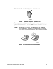
... that may damage the socket pins if installed improperly. Orient the processor with socket opening before installation. Caution: The underside of the processor has components that the processor cut-outs match the socket notches (see letter "B"). A B AF002223 Figure 12. Orienting and Installing Processor Intel® Compute Module MFS5000SI User Guide 13 If present, remove the protective shipping cover...
... that may damage the socket pins if installed improperly. Orient the processor with socket opening before installation. Caution: The underside of the processor has components that the processor cut-outs match the socket notches (see letter "B"). A B AF002223 Figure 12. Orienting and Installing Processor Intel® Compute Module MFS5000SI User Guide 13 If present, remove the protective shipping cover...

User Guide
Page 26
... the socket lever until it is intact on the heatsink. 14 Intel® Compute Module MFS5000SI User Guide Ensure that will not be replaced. C A B AF002224 Figure 14. Remove the socket protective cover. Note: Retain the socket protective cover for future use when removing a processor that the thermal material is fully latched (see letter "A" in the...
... the socket lever until it is intact on the heatsink. 14 Intel® Compute Module MFS5000SI User Guide Ensure that will not be replaced. C A B AF002224 Figure 14. Remove the socket protective cover. Note: Retain the socket protective cover for future use when removing a processor that the thermal material is fully latched (see letter "A" in the...

User Guide
Page 28
Caution: This step only applies if your system has TWO processors. Remove the second processor air baffle by rocking the air baffle back and forth until it breaks off (see letter "A" in place to ensure proper cooling for two processors. For a oneprocessor configuration, the second processor air baffle must be removed to ensure proper cooling. Removing Second Processor Air Baffle 16 Intel® Compute Module MFS5000SI User Guide 14. A AF002410 Figure 16. If you are installing a second processor then the second processor air baffle must remain in the following figure).
Caution: This step only applies if your system has TWO processors. Remove the second processor air baffle by rocking the air baffle back and forth until it breaks off (see letter "A" in place to ensure proper cooling for two processors. For a oneprocessor configuration, the second processor air baffle must be removed to ensure proper cooling. Removing Second Processor Air Baffle 16 Intel® Compute Module MFS5000SI User Guide 14. A AF002410 Figure 16. If you are installing a second processor then the second processor air baffle must remain in the following figure).
User Guide
Page 29
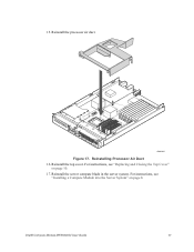
15. Reinstall the server compute blade in the server system. Reinstall the processor air duct. 1 I/O 2 1 2 ID AF002405 Figure 17. Reinstall the top cover. For instructions, see "Replacing and Closing the Top Cover" on page 8. Intel® Compute Module MFS5000SI User Guide 17 For instructions, see "Installing a Compute Module into the Server System" on page 10. 17. Reinstalling Processor Air Duct 16.
15. Reinstall the server compute blade in the server system. Reinstall the processor air duct. 1 I/O 2 1 2 ID AF002405 Figure 17. Reinstall the top cover. For instructions, see "Replacing and Closing the Top Cover" on page 8. Intel® Compute Module MFS5000SI User Guide 17 For instructions, see "Installing a Compute Module into the Server System" on page 10. 17. Reinstalling Processor Air Duct 16.
User Guide
Page 30
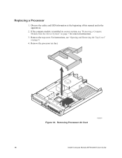
Remove the top cover. If the compute module is installed in the appendices. 2. For instructions, see "Removing a Compute Module from the Server System" on page 8. 4. Remove the processor air duct. 1 I/O 2 1 2 ID Figure 18. Observe the safety and ESD information at the beginning of this manual and in a server system, see "Opening and Removing the Top Cover" on page 7 for removal instructions. 3. Replacing a Processor 1. Removing Processor Air Duct AF002404 18 Intel® Compute Module MFS5000SI User Guide
Remove the top cover. If the compute module is installed in the appendices. 2. For instructions, see "Removing a Compute Module from the Server System" on page 8. 4. Remove the processor air duct. 1 I/O 2 1 2 ID Figure 18. Observe the safety and ESD information at the beginning of this manual and in a server system, see "Opening and Removing the Top Cover" on page 7 for removal instructions. 3. Replacing a Processor 1. Removing Processor Air Duct AF002404 18 Intel® Compute Module MFS5000SI User Guide

User Guide
Page 31
Push the lever handle down and away from the socket to release it. TP02074 Figure 20. Fully raise the socket handle. Carefully remove the processor heatsink by fully loosening the captive screws on the heatsink, and then gently lifting the heatsink off the processor. 3 2 1 4 AF002221 Figure 19. 5. Lifting Processor Socket Handle Intel® Compute Module MFS5000SI User Guide 19 Removing the Heatsink 6.
Push the lever handle down and away from the socket to release it. TP02074 Figure 20. Fully raise the socket handle. Carefully remove the processor heatsink by fully loosening the captive screws on the heatsink, and then gently lifting the heatsink off the processor. 3 2 1 4 AF002221 Figure 19. 5. Lifting Processor Socket Handle Intel® Compute Module MFS5000SI User Guide 19 Removing the Heatsink 6.

User Guide
Page 32
Open the load plate (see letter "A" in the following figure) to bring the front end of the load plate with your finger tip (see letter "B"). they are very sensitive and easily damaged. Removing Processor 20 Intel® Compute Module MFS5000SI User Guide Opening Load Plate 8. AF002225 Figure 22. 7. A B TP02075 Figure 21. Note: Do not touch the socket pins; Remove processor. Push the rear tab of the load plate up slightly.
Open the load plate (see letter "A" in the following figure) to bring the front end of the load plate with your finger tip (see letter "B"). they are very sensitive and easily damaged. Removing Processor 20 Intel® Compute Module MFS5000SI User Guide Opening Load Plate 8. AF002225 Figure 22. 7. A B TP02075 Figure 21. Note: Do not touch the socket pins; Remove processor. Push the rear tab of the load plate up slightly.

User Guide
Page 33
... figure). With your finger, push down on the load plate (see letter "B"). Orienting and Installing Processor 11. Lower the processor load plate (see letter "C"). Lowering Load Plate and Socket Lever Intel® Compute Module MFS5000SI User Guide 21 Install the replacement processor (see letter "B"). Lower the socket lever until it is fully latched (see letter "A" in the...
... figure). With your finger, push down on the load plate (see letter "B"). Orienting and Installing Processor 11. Lower the processor load plate (see letter "C"). Lowering Load Plate and Socket Lever Intel® Compute Module MFS5000SI User Guide 21 Install the replacement processor (see letter "B"). Lower the socket lever until it is fully latched (see letter "A" in the...

User Guide
Page 34
... captive screws in the following figure). Do not over the processor, thermal material side down firmly on the bottom of the heatsink. 13. Press firmly on the heatsink retention module. Align the heatsink over -tighten the screws by using excessive force. 3 2 1 4 TP02328 Figure 26. Re-installing Heatsink 22 Intel® Compute Module MFS5000SI User Guide 12.
... captive screws in the following figure). Do not over the processor, thermal material side down firmly on the bottom of the heatsink. 13. Press firmly on the heatsink retention module. Align the heatsink over -tighten the screws by using excessive force. 3 2 1 4 TP02328 Figure 26. Re-installing Heatsink 22 Intel® Compute Module MFS5000SI User Guide 12.

User Guide
Page 35
Reinstall the top cover. For instructions, see "Replacing and Closing the Top Cover" on page 8. Reinstalling Processor Air Duct 16. Intel® Compute Module MFS5000SI User Guide 23 For instructions, see "Installing a Compute Module into the Server System" on page 10. 17. 15. Reinstall the processor air duct. 1 I/O 2 1 2 ID AF002405 Figure 27. Reinstall the server compute blade in the server system.
Reinstall the top cover. For instructions, see "Replacing and Closing the Top Cover" on page 8. Reinstalling Processor Air Duct 16. Intel® Compute Module MFS5000SI User Guide 23 For instructions, see "Installing a Compute Module into the Server System" on page 10. 17. 15. Reinstall the processor air duct. 1 I/O 2 1 2 ID AF002405 Figure 27. Reinstall the server compute blade in the server system.

User Guide
Page 38
Remove the processor air duct. 1 I/O 2 1 2 ID Figure 29. Holding the DIMM by the edges, remove it from it's packaging. Removing Processor Air Duct 5. Locate the DIMM sockets. 6. AF002404 26 Intel® Compute Module MFS5000SI User Guide 4.
Remove the processor air duct. 1 I/O 2 1 2 ID Figure 29. Holding the DIMM by the edges, remove it from it's packaging. Removing Processor Air Duct 5. Locate the DIMM sockets. 6. AF002404 26 Intel® Compute Module MFS5000SI User Guide 4.
User Guide
Page 40
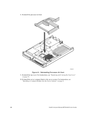
8. For instructions, see "Installing a Compute Module into the Server System" on page 10. 10. Reinstall the server compute blade in the server system. Reinstall the top cover. For instructions, see "Replacing and Closing the Top Cover" on page 8. 28 Intel® Compute Module MFS5000SI User Guide Reinstall the processor air duct. 1 I/O 2 1 2 ID AF002405 Figure 31. Reinstalling Processor Air Duct 9.
8. For instructions, see "Installing a Compute Module into the Server System" on page 10. 10. Reinstall the server compute blade in the server system. Reinstall the top cover. For instructions, see "Replacing and Closing the Top Cover" on page 8. 28 Intel® Compute Module MFS5000SI User Guide Reinstall the processor air duct. 1 I/O 2 1 2 ID AF002405 Figure 31. Reinstalling Processor Air Duct 9.
User Guide
Page 41
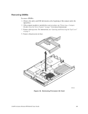
Removing DIMMs To remove DIMMs: 1. Observe the safety and ESD information at the beginning of this manual and in a server system, see "Opening and Removing the Top Cover" on page 7 for removal instructions. 3. If the compute module is installed in the appendices. 2. Remove the processor air duct. 1 I/O 2 1 2 ID Figure 32. For instructions, see "Removing a Compute Module from the Server System" on page 8. 4. Remove the top cover. Removing Processor Air Duct AF002404 Intel® Compute Module MFS5000SI User Guide 29
Removing DIMMs To remove DIMMs: 1. Observe the safety and ESD information at the beginning of this manual and in a server system, see "Opening and Removing the Top Cover" on page 7 for removal instructions. 3. If the compute module is installed in the appendices. 2. Remove the processor air duct. 1 I/O 2 1 2 ID Figure 32. For instructions, see "Removing a Compute Module from the Server System" on page 8. 4. Remove the top cover. Removing Processor Air Duct AF002404 Intel® Compute Module MFS5000SI User Guide 29