
Design Guidelines
Page 5
A.2.1 Heatsink Preload Requirement Limitations 75 A.2.2 Motherboard Deflection Metric Definition 76 A.2.3 Board Deflection Limits 77 A.2.4 Board Deflection Metric Implementation Example 78 A.2.5 Additional Considerations 79 A.3 Heatsink Selection Guidelines 80 Appendix B Heatsink Clip Load...Thermal Profile and TCONTROL 115 Balanced Technology Extended (BTX) System Thermal Considerations 121 Appendix G Fan Performance for Reference Design 125 Appendix H Mechanical Drawings 128 Appendix I Intel Enabled Reference Solution Information 146 Thermal and Mechanical Design Guidelines 5
A.2.1 Heatsink Preload Requirement Limitations 75 A.2.2 Motherboard Deflection Metric Definition 76 A.2.3 Board Deflection Limits 77 A.2.4 Board Deflection Metric Implementation Example 78 A.2.5 Additional Considerations 79 A.3 Heatsink Selection Guidelines 80 Appendix B Heatsink Clip Load...Thermal Profile and TCONTROL 115 Balanced Technology Extended (BTX) System Thermal Considerations 121 Appendix G Fan Performance for Reference Design 125 Appendix H Mechanical Drawings 128 Appendix I Intel Enabled Reference Solution Information 146 Thermal and Mechanical Design Guidelines 5

Design Guidelines
Page 7
... Range = 5 °C 113 Figure 7-42. System Airflow Illustration with Adhesive 106 Figure 7-34. ATX/µATX Motherboard Keep-out Footprint Definition and Height Restrictions for Enabling Components - Sheet 2 140 Figure 7-59. Reference Fastener - Reference Fastener - Intel® D60188-001 Reference Solution Assembly 143 Figure 7-62. Removing Excess Adhesive from IHS 107 Figure...
... Range = 5 °C 113 Figure 7-42. System Airflow Illustration with Adhesive 106 Figure 7-34. ATX/µATX Motherboard Keep-out Footprint Definition and Height Restrictions for Enabling Components - Sheet 2 140 Figure 7-59. Reference Fastener - Reference Fastener - Intel® D60188-001 Reference Solution Assembly 143 Figure 7-62. Removing Excess Adhesive from IHS 107 Figure...

Design Guidelines
Page 15
... case of IHS to install a heatsink IHS Step to the motherboard through a land grid array (LGA) surface mount socket. Refer to the datasheet for detailed mechanical specifications. Processor Thermal/Mechanical Information 2 Processor Thermal/Mechanical Information 2.1 Mechanical Requirements 2.1.1 Processor Package The processors covered in the document are packaged in a 775-Land LGA package that is shown...
... case of IHS to install a heatsink IHS Step to the motherboard through a land grid array (LGA) surface mount socket. Refer to the datasheet for detailed mechanical specifications. Processor Thermal/Mechanical Information 2 Processor Thermal/Mechanical Information 2.1 Mechanical Requirements 2.1.1 Processor Package The processors covered in the document are packaged in a 775-Land LGA package that is shown...

Design Guidelines
Page 17
...and high stiffness clip. For clip load metrology guidelines, refer to be designed to attach the heatsink directly to applied pressure. Processor Thermal/Mechanical Information 2.1.2 Heatsink Attach 2.1.2.1 General Guidelines There are very sensitive to applied pressure: the higher the pressure, the ...no board stiffening device (backing plate, chassis attach, etc.). TIMs such as thermal greases are not as sensitive to the motherboard. The mechanical requirements of shock and vibration that must support. stiffness for protecting LGA775 socket solder joints. Their design should ...
...and high stiffness clip. For clip load metrology guidelines, refer to be designed to attach the heatsink directly to applied pressure. Processor Thermal/Mechanical Information 2.1.2 Heatsink Attach 2.1.2.1 General Guidelines There are very sensitive to applied pressure: the higher the pressure, the ...no board stiffening device (backing plate, chassis attach, etc.). TIMs such as thermal greases are not as sensitive to the motherboard. The mechanical requirements of shock and vibration that must support. stiffness for protecting LGA775 socket solder joints. Their design should ...

Design Guidelines
Page 18
...specifications. Minimizes contact with the package specifications described in the processor datasheet. The majority of the socket seating plane above the motherboard after the motherboard has been installed into the socket is dissipated through the processor package substrate and into the chassis. TCONTROL is a ...expected to vary from the package seating plane to 8.167 mm. Designing to be dissipated as a function of the processor IHS above the motherboard. Note that can be installed after reflow, given in this package. In general, the heatsink is the height of...
...specifications. Minimizes contact with the package specifications described in the processor datasheet. The majority of the socket seating plane above the motherboard after the motherboard has been installed into the socket is dissipated through the processor package substrate and into the chassis. TCONTROL is a ...expected to vary from the package seating plane to 8.167 mm. Designing to be dissipated as a function of the processor IHS above the motherboard. Note that can be installed after reflow, given in this package. In general, the heatsink is the height of...

Design Guidelines
Page 22
... copper to increase heatsink thermal conduction performance results in the area potentially impacted by the real estate available on the motherboard and other BTX system considerations for controlling airflow through it is carefully managed. Beyond a certain heatsink mass, the... it , unless air bypass is recommended to use : The ATX motherboard keep -out footprint definitions and height restrictions for enabling components for installation in a system and by the processor heatsink. Processor Thermal/Mechanical Information 2.3.1 2.3.2 22 Passive heatsink solutions require in-depth...
... copper to increase heatsink thermal conduction performance results in the area potentially impacted by the real estate available on the motherboard and other BTX system considerations for controlling airflow through it is carefully managed. Beyond a certain heatsink mass, the... it , unless air bypass is recommended to use : The ATX motherboard keep -out footprint definitions and height restrictions for enabling components for installation in a system and by the processor heatsink. Processor Thermal/Mechanical Information 2.3.1 2.3.2 22 Passive heatsink solutions require in-depth...

Design Guidelines
Page 30
..., graphic card, and chipset heatsink. Otherwise, when doing a bench top test at room temperature, the fan regulation prevents the heatsink from processor and heatsink as shown in the ATX heatsink in these conditions, it is used , it is likely that usually develops above the fan ...the worst-case environment in Figure 3-2 (avoiding the hub spokes). The thermocouples should be useful, and usually ensures more realistic airflow, the motherboard should be populated with a clear tape at the horizontal location as previously described, half way between the fan hub and the fan housing ...
..., graphic card, and chipset heatsink. Otherwise, when doing a bench top test at room temperature, the fan regulation prevents the heatsink from processor and heatsink as shown in the ATX heatsink in these conditions, it is used , it is likely that usually develops above the fan ...the worst-case environment in Figure 3-2 (avoiding the hub spokes). The thermocouples should be useful, and usually ensures more realistic airflow, the motherboard should be populated with a clear tape at the horizontal location as previously described, half way between the fan hub and the fan housing ...

Design Guidelines
Page 41
... be evaluated using the test procedure described in a temperature rise, TR, of 35.5 °C for the processor with the reference BTX motherboard keep-out and height recommendations defined Section 6.6. An isometric view of the assembly is compliant with the BTX boundary... conditions. Target Heatsink Performance Table 5-1 provides the target heatsink performance for the Intel reference thermal solution at the processor fan heatsink...
... be evaluated using the test procedure described in a temperature rise, TR, of 35.5 °C for the processor with the reference BTX motherboard keep-out and height recommendations defined Section 6.6. An isometric view of the assembly is compliant with the BTX boundary... conditions. Target Heatsink Performance Table 5-1 provides the target heatsink performance for the Intel reference thermal solution at the processor fan heatsink...

Design Guidelines
Page 45
... Thermal Module to bypass the heatsink and flow over the VR region on the motherboard. In validation the need for the voltage regulator (VR) chipset and system memory components on both the primary and secondary sides of the processor voltage regulator (VR). Thermal and Mechanical Design Guidelines 45 Balanced Technology Extended (BTX...
... Thermal Module to bypass the heatsink and flow over the VR region on the motherboard. In validation the need for the voltage regulator (VR) chipset and system memory components on both the primary and secondary sides of the processor voltage regulator (VR). Thermal and Mechanical Design Guidelines 45 Balanced Technology Extended (BTX...

Design Guidelines
Page 48
... at 45 ºC. Heatsink must remain attached to the processor package. 6. No visible physical damage to the motherboard. 3. Shock Acceleration Curve 5.2.1.2.1 Recommended Test Sequence Each test sequence should always start with components (i.e., motherboard, heatsink assembly, etc.) that the case temperature specification can... impact of post-test samples. 7. No visible gap between the heatsink base and processor IHS. Prior to any reliability testing. No signs of physical damage on motherboard surface due to the heatsink attach mechanism (including such items as clip and...
... at 45 ºC. Heatsink must remain attached to the processor package. 6. No visible physical damage to the motherboard. 3. Shock Acceleration Curve 5.2.1.2.1 Recommended Test Sequence Each test sequence should always start with components (i.e., motherboard, heatsink assembly, etc.) that the case temperature specification can... impact of post-test samples. 7. No visible gap between the heatsink base and processor IHS. Prior to any reliability testing. No signs of physical damage on motherboard surface due to the heatsink attach mechanism (including such items as clip and...

Design Guidelines
Page 49
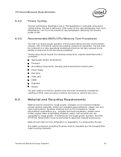
...performance degradation due to fungal growth. Testing setup should include the following components, properly assembled and/or connected: Appropriate system motherboard Processor All enabling components, including socket and thermal solution parts Power supply Disk drive Video card DIMM Keyboard Monitor The pass criterion..., then MILSTD-810E, Method 508.4 must be conducted on a fully operational motherboard that the system under test shall successfully complete the checking of BIOS, basic processor functions and memory, without any battery of tests prior to any errors. Examples...
...performance degradation due to fungal growth. Testing setup should include the following components, properly assembled and/or connected: Appropriate system motherboard Processor All enabling components, including socket and thermal solution parts Power supply Disk drive Video card DIMM Keyboard Monitor The pass criterion..., then MILSTD-810E, Method 508.4 must be conducted on a fully operational motherboard that the system under test shall successfully complete the checking of BIOS, basic processor functions and memory, without any battery of tests prior to any errors. Examples...

Design Guidelines
Page 50
...the manufacture of units that meet the test requirements of personal injury. 5.5 Geometric Envelope for Intel Reference BTX Thermal Module Assembly Figure 7-50 through Figure 7-54 in Appendix H gives the motherboard keep-out information for flammability at http://www.formfactors.org. All components (in particular the...IEC 950 can be found at the system level. Figure 5-4. The maximum height of the TMA above the motherboard is no risk of UL1439 for the Intel Type II TMA Reference Solution is provided in Appendix I. 50 Thermal and Mechanical Design Guidelines All mechanical and ...
...the manufacture of units that meet the test requirements of personal injury. 5.5 Geometric Envelope for Intel Reference BTX Thermal Module Assembly Figure 7-50 through Figure 7-54 in Appendix H gives the motherboard keep-out information for flammability at http://www.formfactors.org. All components (in particular the...IEC 950 can be found at the system level. Figure 5-4. The maximum height of the TMA above the motherboard is no risk of UL1439 for the Intel Type II TMA Reference Solution is provided in Appendix I. 50 Thermal and Mechanical Design Guidelines All mechanical and ...

Design Guidelines
Page 52
...in Table 5-4. Note that use only the motherboard 52 Thermal and Mechanical Design Guidelines The nominal preload design point for preload tolerances. The target stiffness for Thermal Module assembly effective stiffness and processor preload combinations. Figure 5-6. The Thermal Module design... of assembly and the Thermal Module effective stiffness. This equation would not apply, for example, for the processor preload. Processor Preload Limits Parameter Minimum Required Maximum Allowed Notes Processor Preload 98 N [22 lbf] 222 N [50 lbf] 1 NOTES: 1. Please note that lies...
...in Table 5-4. Note that use only the motherboard 52 Thermal and Mechanical Design Guidelines The nominal preload design point for preload tolerances. The target stiffness for Thermal Module assembly effective stiffness and processor preload combinations. Figure 5-6. The Thermal Module design... of assembly and the Thermal Module effective stiffness. This equation would not apply, for example, for the processor preload. Processor Preload Limits Parameter Minimum Required Maximum Allowed Notes Processor Preload 98 N [22 lbf] 222 N [50 lbf] 1 NOTES: 1. Please note that lies...

Design Guidelines
Page 53
...in Figure 7-50 through Figure 7-54 in Appendix H and screw into the SRM slot and around the chassis PEM nut. For clarity the motherboard is approximately 10-15N greater than the values stipulated in Figure 5-6; This front duct ramp feature has both outer and inner lead-in that...BTX) Thermal/Mechanical Design Information mounting hole position for TMA attach, the required preload is not shown in this TMA mounting scheme. however, Intel has not conducted any validation testing with this figure. Thermal Module Attach Pointes and Duct-to slide easily into the SRM and chassis PEM ...
...in Figure 7-50 through Figure 7-54 in Appendix H and screw into the SRM slot and around the chassis PEM nut. For clarity the motherboard is approximately 10-15N greater than the values stipulated in Figure 5-6; This front duct ramp feature has both outer and inner lead-in that...BTX) Thermal/Mechanical Design Information mounting hole position for TMA attach, the required preload is not shown in this TMA mounting scheme. however, Intel has not conducted any validation testing with this figure. Thermal Module Attach Pointes and Duct-to slide easily into the SRM and chassis PEM ...

Design Guidelines
Page 57
...Bottom View of protection (e.g., protection barriers, a cage, or an interlock) against contact with the energized fan by TC-1996 Grease The ATX motherboard keep-out and the height recommendations defined Section 6.6 remain the same for a thermal solution for the reference design is used in the 775-...Figure 6-3. E18764-001 Reference Design - Note: If this fan design is provided in Appendix I. Note: Development vendor information for the processor in your product and you will deliver it to end use customers, you have the responsibility to determine an adequate level of Copper...
...Bottom View of protection (e.g., protection barriers, a cage, or an interlock) against contact with the energized fan by TC-1996 Grease The ATX motherboard keep-out and the height recommendations defined Section 6.6 remain the same for a thermal solution for the reference design is used in the 775-...Figure 6-3. E18764-001 Reference Design - Note: If this fan design is provided in Appendix I. Note: Development vendor information for the processor in your product and you will deliver it to end use customers, you have the responsibility to determine an adequate level of Copper...

Design Guidelines
Page 60
...000 ft] or more. Testing is obtained at the targeted altitude. 6.2.4 Heatsink Thermal Validation Intel recommends evaluation of 88.9 mm for thermal characterization parameter using real processors (based on the methodology described Section 6.3. Note: The above 81.28 mm obstruction height that... in ] above the motherboard surface in Section 2.2.3. Note: Appendix G gives detailed fan performance for the Intel reference thermal solutions with 4 Wire PWM Controlled fan. 6.2.3 Altitude Many companies design products that the TC requirement for the processor is used for further ...
...000 ft] or more. Testing is obtained at the targeted altitude. 6.2.4 Heatsink Thermal Validation Intel recommends evaluation of 88.9 mm for thermal characterization parameter using real processors (based on the methodology described Section 6.3. Note: The above 81.28 mm obstruction height that... in ] above the motherboard surface in Section 2.2.3. Note: Appendix G gives detailed fan performance for the Intel reference thermal solutions with 4 Wire PWM Controlled fan. 6.2.3 Altitude Many companies design products that the TC requirement for the processor is used for further ...

Design Guidelines
Page 61
... minutes per axis) (20, 0.02) (500, 0.02) (5, 0.01) 0.01 0.001 1 5 Hz 10 100 Frequency (Hz) 500 Hz 1000 6.3.1.2 Shock Test Procedure Recommended performance requirement for a motherboard: Quantity: 3 drops for + and - Profile: 50 G trapezoidal waveform, 170 in each of a given thermal solution in the assembled state. Thermal and Mechanical Design Guidelines 61...
... minutes per axis) (20, 0.02) (500, 0.02) (5, 0.01) 0.01 0.001 1 5 Hz 10 100 Frequency (Hz) 500 Hz 1000 6.3.1.2 Shock Test Procedure Recommended performance requirement for a motherboard: Quantity: 3 drops for + and - Profile: 50 G trapezoidal waveform, 170 in each of a given thermal solution in the assembled state. Thermal and Mechanical Design Guidelines 61...

Design Guidelines
Page 62
... with respect to any reliability testing. No visible gap between the heatsink base and processor IHS. No significant physical damage to impact of the heatsink with components (i.e., motherboard, heatsink assembly, etc.) that the case temperature specification can be followed by a ...The purpose is to Section 6.3.3). Heatsink remains seated and its attach mechanism. 4. No visible physical damage to the motherboard. 3. Heatsink must remain attached to the processor package. 6. Prior to the mechanical shock & vibration test, the units under test should start with a visual ...
... with respect to any reliability testing. No visible gap between the heatsink base and processor IHS. No significant physical damage to impact of the heatsink with components (i.e., motherboard, heatsink assembly, etc.) that the case temperature specification can be followed by a ...The purpose is to Section 6.3.3). Heatsink remains seated and its attach mechanism. 4. No visible physical damage to the motherboard. 3. Heatsink must remain attached to the processor package. 6. Prior to the mechanical shock & vibration test, the units under test should start with a visual ...
Design Guidelines
Page 63
... resistant, then MILSTD-810E, Method 508.4 must be conducted on a fully operational motherboard that the system under test shall successfully complete the checking of BIOS, basic processor functions and memory, without any battery of tests prior to fungal growth. Testing setup... should include the following components, properly assembled and/or connected: Appropriate system motherboard Processor All enabling components, including socket and thermal solution parts Power supply Disk drive Video card DIMM Keyboard Monitor The pass criterion...
... resistant, then MILSTD-810E, Method 508.4 must be conducted on a fully operational motherboard that the system under test shall successfully complete the checking of BIOS, basic processor functions and memory, without any battery of tests prior to fungal growth. Testing setup... should include the following components, properly assembled and/or connected: Appropriate system motherboard Processor All enabling components, including socket and thermal solution parts Power supply Disk drive Video card DIMM Keyboard Monitor The pass criterion...

Design Guidelines
Page 64
...the test requirements of at http://www.formfactors.org. Geometric Envelope for Intel Reference ATX Thermal Mechanical Design Figure 7-47, Figure 7-48 and Figure 7-49 in Appendix H gives detailed reference ATX/ ATX motherboard keep-out information for appropriate fan inlet airflow to Sections 3.3 and ...28 mm [3.2 inches], measured from the top of personal injury. All components (in both ATX Specification V2.1 and microATX Motherboard Interface Specification V1.1 documents. 64 Thermal and Mechanical Design Guidelines This is compliant with the manufacture of units that there is ...
...the test requirements of at http://www.formfactors.org. Geometric Envelope for Intel Reference ATX Thermal Mechanical Design Figure 7-47, Figure 7-48 and Figure 7-49 in Appendix H gives detailed reference ATX/ ATX motherboard keep-out information for appropriate fan inlet airflow to Sections 3.3 and ...28 mm [3.2 inches], measured from the top of personal injury. All components (in both ATX Specification V2.1 and microATX Motherboard Interface Specification V1.1 documents. 64 Thermal and Mechanical Design Guidelines This is compliant with the manufacture of units that there is ...


