Design Guidelines
Page 1
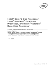
Intel® Celeron® Dual-Core Processor E1000 Series June 2009 Document Number: 317804-011 Intel® Pentium® Dual Core Processor E2000 Series - Intel® Core™2 Duo Processor E6000 and E4000 Series - Intel® Core™2 Duo Processor, Intel® Pentium® Dual Core Processor, and Intel® Celeron® Dual-Core Processor Thermal and Mechanical Design Guidelines Supporting the: -
Intel® Celeron® Dual-Core Processor E1000 Series June 2009 Document Number: 317804-011 Intel® Pentium® Dual Core Processor E2000 Series - Intel® Core™2 Duo Processor E6000 and E4000 Series - Intel® Core™2 Duo Processor, Intel® Pentium® Dual Core Processor, and Intel® Celeron® Dual-Core Processor Thermal and Mechanical Design Guidelines Supporting the: -

Design Guidelines
Page 5
...Line Management 87 C.2 Interface Material Area 87 C.3 Interface Material Performance 87 Appendix D Case Temperature Reference Metrology 89 D.1 Objective and Scope 89 D.2 Supporting Test Equipment 89 D.3 Thermal Calibration and Controls 91 D.4 IHS Groove 91 D.5 Thermocouple Attach Procedure 95 D.5.1 D.5.2 D.5.3 D.5.4 Thermocouple Conditioning and Preparation... Considerations 121 Appendix G Fan Performance for Reference Design 125 Appendix H Mechanical Drawings 128 Appendix I Intel Enabled Reference Solution Information 146 Thermal and Mechanical Design Guidelines 5
...Line Management 87 C.2 Interface Material Area 87 C.3 Interface Material Performance 87 Appendix D Case Temperature Reference Metrology 89 D.1 Objective and Scope 89 D.2 Supporting Test Equipment 89 D.3 Thermal Calibration and Controls 91 D.4 IHS Groove 91 D.5 Thermocouple Attach Procedure 95 D.5.1 D.5.2 D.5.3 D.5.4 Thermocouple Conditioning and Preparation... Considerations 121 Appendix G Fan Performance for Reference Design 125 Appendix H Mechanical Drawings 128 Appendix I Intel Enabled Reference Solution Information 146 Thermal and Mechanical Design Guidelines 5

Design Guidelines
Page 12
... Scope This design guide supports the following processors: Intel® Core™2 Duo processor with 4 MB cache at Tc-max of 60.1 °C applies to Intel® Core™2 Duo processors E6700, E6600, E6420 and E6320 Intel® Core™2 Duo processor with 4 MB cache at Tc-max of 72.0 °C applies to Intel® Core™2 Duo processors E6850, E6750, E6550 and E6540 Intel® Core™2 Duo processor with 2 MB cache...
... Scope This design guide supports the following processors: Intel® Core™2 Duo processor with 4 MB cache at Tc-max of 60.1 °C applies to Intel® Core™2 Duo processors E6700, E6600, E6420 and E6320 Intel® Core™2 Duo processor with 4 MB cache at Tc-max of 72.0 °C applies to Intel® Core™2 Duo processors E6850, E6750, E6550 and E6540 Intel® Core™2 Duo processor with 2 MB cache...

Design Guidelines
Page 17
... attach mechanism depend on the package between the IHS and the heatsink. For clip load metrology guidelines, refer to applied pressure. Processor Thermal/Mechanical Information 2.1.2 Heatsink Attach 2.1.2.1 General Guidelines There are no board stiffening device (backing plate, chassis attach, etc.). Note...are very sensitive to be designed to attach the heatsink directly to the required minimum load. It is required to support the processor should provide a means for mechanical protection of shock and vibration that must be considered when designing the heatsink attach ...
... attach mechanism depend on the package between the IHS and the heatsink. For clip load metrology guidelines, refer to applied pressure. Processor Thermal/Mechanical Information 2.1.2 Heatsink Attach 2.1.2.1 General Guidelines There are no board stiffening device (backing plate, chassis attach, etc.). Note...are very sensitive to be designed to attach the heatsink directly to the required minimum load. It is required to support the processor should provide a means for mechanical protection of shock and vibration that must be considered when designing the heatsink attach ...

Design Guidelines
Page 33
... Logic and Thermal Monitor Feature 4 Thermal Management Logic and Thermal Monitor Feature 4.1 4.2 Processor Power Dissipation An increase in Section 4.2.3. It provides a thermal management approach to determine the processor thermal status. Registers to support the continued increases in the hundreds of a processor, and Intel is available on -die temperature sensing circuit A bi-directional signal (PROCHOT#) that...
... Logic and Thermal Monitor Feature 4 Thermal Management Logic and Thermal Monitor Feature 4.1 4.2 Processor Power Dissipation An increase in Section 4.2.3. It provides a thermal management approach to determine the processor thermal status. Registers to support the continued increases in the hundreds of a processor, and Intel is available on -die temperature sensing circuit A bi-directional signal (PROCHOT#) that...

Design Guidelines
Page 35
... by dropping the bus-to-core multiplier to execute instructions during the voltage transition. Edge-triggered interrupts will be latched and kept pending until the processor resumes operation at the lower voltage reduces the power consumption of the processor, providing a temperature reduction. The voltage regulator must support VID transitions in processor power consumption. This transition...
... by dropping the bus-to-core multiplier to execute instructions during the voltage transition. Edge-triggered interrupts will be latched and kept pending until the processor resumes operation at the lower voltage reduces the power consumption of the processor, providing a temperature reduction. The voltage regulator must support VID transitions in processor power consumption. This transition...
Design Guidelines
Page 43
...TMA only when installed in the validation report but this condition is predicting that the power supply fan will be adjusted to support the processor thermal profile, additional acoustic improvements can be the acoustic limiter. 4. The designer should identify the fan speed required to ... The acoustic model is not a target for one of measured sound power (LwA) as defined in Section 2.2.3. Refer to Chapter 7 for the Intel reference thermal solutions with 4 Wire PWM Controlled to ISO 7779. 2. Note: Appendix G gives detailed fan performance for further details. Acoustic Targets Fan ...
...TMA only when installed in the validation report but this condition is predicting that the power supply fan will be adjusted to support the processor thermal profile, additional acoustic improvements can be the acoustic limiter. 4. The designer should identify the fan speed required to ... The acoustic model is not a target for one of measured sound power (LwA) as defined in Section 2.2.3. Refer to Chapter 7 for the Intel reference thermal solutions with 4 Wire PWM Controlled to ISO 7779. 2. Note: Appendix G gives detailed fan performance for further details. Acoustic Targets Fan ...

Design Guidelines
Page 46
... and shock tests of a given thermal solution in the assembled state. However, many companies design products that the TC requirement for the processor is met at sea level. Testing is done in order to what is at high altitude, typically 1,500 m [5,000 ft] or... a worst-case mean + 3 value for the Intel® 965 Express Chipset Family. 5.1.5 Altitude The reference TMA will be adjusted to take into account altitude effects like variation in thermal solution performance compared to support the 775_VR_CONFIG_06 processors at TDP power dissipation and the chassis external environment...
... and shock tests of a given thermal solution in the assembled state. However, many companies design products that the TC requirement for the processor is met at sea level. Testing is done in order to what is at high altitude, typically 1,500 m [5,000 ft] or... a worst-case mean + 3 value for the Intel® 965 Express Chipset Family. 5.1.5 Altitude The reference TMA will be adjusted to take into account altitude effects like variation in thermal solution performance compared to support the 775_VR_CONFIG_06 processors at TDP power dissipation and the chassis external environment...

Design Guidelines
Page 52
...Required Processor Preload...equation for preload tolerances. This equation would not apply, for example, for the processor preload. The equation for this region. The shaded region shown is the acceptable ...38E-3*k^2 - 1.18486k + 320.24753 for Thermal Module assembly effective stiffness and processor preload combinations. The nominal preload design point for the 65W Type II TMA ... stiffness for the Thermal Module is 484 N/mm (2764 lb / in). Processor Preload Limits Parameter Minimum Required Maximum Allowed Notes Processor Preload 98 N [22 lbf] 222 N [50 lbf] 1 NOTES: ...
...Required Processor Preload...equation for preload tolerances. This equation would not apply, for example, for the processor preload. The equation for this region. The shaded region shown is the acceptable ...38E-3*k^2 - 1.18486k + 320.24753 for Thermal Module assembly effective stiffness and processor preload combinations. The nominal preload design point for the 65W Type II TMA ... stiffness for the Thermal Module is 484 N/mm (2764 lb / in). Processor Preload Limits Parameter Minimum Required Maximum Allowed Notes Processor Preload 98 N [22 lbf] 222 N [50 lbf] 1 NOTES: ...

Design Guidelines
Page 56
... material (Dow Corning TC-1996 grease, see uATX SFF Guidance for reference only. The overall 46mm height thermal solution supports the unique and smaller desktop PCs including small and ultra small form factors, down to the E18764-001 reference design;... View The processors of Intel® Core™2 Duo processor with 4 MB / 2 MB cache at Tc-max of 72.0 °C, Intel® Core™2 Duo processor with 2 MB cache at Tc-max of 73.3 °C, Intel® Pentium® Dual Core processor E2000 series at Tc-max of 73.3 °C, and Intel® Celeron® Dual-Core processor E1000 series...
... material (Dow Corning TC-1996 grease, see uATX SFF Guidance for reference only. The overall 46mm height thermal solution supports the unique and smaller desktop PCs including small and ultra small form factors, down to the E18764-001 reference design;... View The processors of Intel® Core™2 Duo processor with 4 MB / 2 MB cache at Tc-max of 72.0 °C, Intel® Core™2 Duo processor with 2 MB cache at Tc-max of 73.3 °C, Intel® Pentium® Dual Core processor E2000 series at Tc-max of 73.3 °C, and Intel® Celeron® Dual-Core processor E1000 series...

Design Guidelines
Page 59
..., ca Notes 3900 High TA = 40 °C 5.0 BA 2000 Low TA = 30 °C 3.5 BA 0.49 C/W (Intel Core™2 Duo processor, 4 MB / 2 MB at Tc-max of 72.0 °C) 0.51 C/W (Intel Core™2 Duo processor, 2 MB at Tc-max of 73.3 °C) 0.51 C/W (E2000 series at Tc-max of 73.3 °C ) ...0.67 C/W (Intel Core™2 Duo processor, 2 MB at Tc-max of 73.3 °C) 0.67 C/W (E2000 series at Tc-max of 73.3 °C) 0.67 C/W (E1000 Series of Tc-max of measured sound power (LwA) as defined in ISO 9296 standard, and measured according to support the processor thermal profile, additional...
..., ca Notes 3900 High TA = 40 °C 5.0 BA 2000 Low TA = 30 °C 3.5 BA 0.49 C/W (Intel Core™2 Duo processor, 4 MB / 2 MB at Tc-max of 72.0 °C) 0.51 C/W (Intel Core™2 Duo processor, 2 MB at Tc-max of 73.3 °C) 0.51 C/W (E2000 series at Tc-max of 73.3 °C ) ...0.67 C/W (Intel Core™2 Duo processor, 2 MB at Tc-max of 73.3 °C) 0.67 C/W (E2000 series at Tc-max of 73.3 °C) 0.67 C/W (E1000 Series of Tc-max of measured sound power (LwA) as defined in ISO 9296 standard, and measured according to support the processor thermal profile, additional...

Design Guidelines
Page 73
... recommendations for placement). Figure 7-4. Additional SST sensors can support processors with a number of major manufacturers of manufacturers and visit their web sites or local sales representatives for a part suitable for your Intel Field Sales representative for the current list of thermal ...devices for the processor socket. Intel® Quiet System Technology (Intel® QST) Figure 7-4 shows the major connections for a typical implementation that is in all of the processors in the 775-land LGA packages shipped before the Intel® Core™2 Duo processor. With the ...
... recommendations for placement). Figure 7-4. Additional SST sensors can support processors with a number of major manufacturers of manufacturers and visit their web sites or local sales representatives for a part suitable for your Intel Field Sales representative for the current list of thermal ...devices for the processor socket. Intel® Quiet System Technology (Intel® QST) Figure 7-4 shows the major connections for a typical implementation that is in all of the processors in the 775-land LGA packages shipped before the Intel® Core™2 Duo processor. With the ...

Design Guidelines
Page 74
... process the Intel QST can be taken in BTX designs to ensure the fan speed at the minimum operating speed provides sufficient air flow to support the other system components. This Variable Speed Fan curve will determine the maximum fan speed as a function of the processor. Care needs... to be modified to have the proper relationships between Intel QST and the thermistor, but this time...
... process the Intel QST can be taken in BTX designs to ensure the fan speed at the minimum operating speed provides sufficient air flow to support the other system components. This Variable Speed Fan curve will determine the maximum fan speed as a function of the processor. Care needs... to be modified to have the proper relationships between Intel QST and the thermistor, but this time...

Design Guidelines
Page 80
...Solutions derived from the reference design comply with the reference heatsink preload, for example: The Boxed Processor The reference design (D60188-001 and E18764-001) Intel will collaborate with the board in the socket area, and prevents the board to heatsink preloads...appropriate in some situations like: Board bending during mechanical shock event Define load paths that is available in Intel® Core™2 Duo Processor Support Components webpage www.intel.com/go/thermal_Core2Duo . § 80 Thermal and Mechanical Design Guidelines Prevent board upward bending during shock Board...
...Solutions derived from the reference design comply with the reference heatsink preload, for example: The Boxed Processor The reference design (D60188-001 and E18764-001) Intel will collaborate with the board in the socket area, and prevents the board to heatsink preloads...appropriate in some situations like: Board bending during mechanical shock event Define load paths that is available in Intel® Core™2 Duo Processor Support Components webpage www.intel.com/go/thermal_Core2Duo . § 80 Thermal and Mechanical Design Guidelines Prevent board upward bending during shock Board...

Design Guidelines
Page 85
Pre-assemble mechanical components on the board as needed prior to mounting the motherboard on an appropriate support fixture that replicate the board attach to target temperature (45 ºC or 85 ºC for the duration of the bake test 5. ...3. Remove assembly from all three load cells) at 1 Hz for example) 2. Record continuous load cell data as well, i.e. Install relevant test vehicle (TTV, processor) in the interval , for specified time 4. target time + 5 seconds]. Place unit into room temperature conditions 6. If the attach mechanism includes fixtures on ATX ...
Pre-assemble mechanical components on the board as needed prior to mounting the motherboard on an appropriate support fixture that replicate the board attach to target temperature (45 ºC or 85 ºC for the duration of the bake test 5. ...3. Remove assembly from all three load cells) at 1 Hz for example) 2. Record continuous load cell data as well, i.e. Install relevant test vehicle (TTV, processor) in the interval , for specified time 4. target time + 5 seconds]. Place unit into room temperature conditions 6. If the attach mechanism includes fixtures on ATX ...

Design Guidelines
Page 89
... following table as a convenience to Intel's general customers and the list may be subject to the IHS followed by the reference procedure. Supplier THERM-X OF CALIFORNIA Contact Ernesto B Valencia Phone 510-441-7566 Ext. 242 Email ernestov@ther m-x.com Address 1837 Whipple Road, Hayward, Ca 94544 Supporting Test Equipment To apply the...
... following table as a convenience to Intel's general customers and the list may be subject to the IHS followed by the reference procedure. Supplier THERM-X OF CALIFORNIA Contact Ernesto B Valencia Phone 510-441-7566 Ext. 242 Email ernestov@ther m-x.com Address 1837 Whipple Road, Hayward, Ca 94544 Supporting Test Equipment To apply the...

Design Guidelines
Page 110
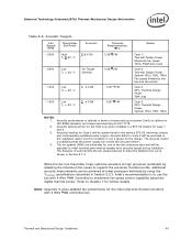
... at minimum RPM for 4 wire PWM Controlled Fans; The fan would be allowed to support commutation. Operating 30 38 Fan Inlet Temperature (°C) E.1.2 Minimum Fan Speed Set Point The final aspect of the design, such as the processor voltage regulator, or by the external fan speed control. Type B: The fan will be...
... at minimum RPM for 4 wire PWM Controlled Fans; The fan would be allowed to support commutation. Operating 30 38 Fan Inlet Temperature (°C) E.1.2 Minimum Fan Speed Set Point The final aspect of the design, such as the processor voltage regulator, or by the external fan speed control. Type B: The fan will be...

Design Guidelines
Page 117
...). Must support PECI and thermal diode using a SST device External/remote thermal sensor sampling rate 4 times per second (required). The motherboard needs to have a fan speed control component that has the following characteristics: PWM output programmable to 25 kHz (Suggested) as this document, the reference thermal solution and Boxed Processor thermal solution... setup or other utility to establish a fan speed control algorithm consistent with this value is the design target for the reference and for the Boxed Processor.
...). Must support PECI and thermal diode using a SST device External/remote thermal sensor sampling rate 4 times per second (required). The motherboard needs to have a fan speed control component that has the following characteristics: PWM output programmable to 25 kHz (Suggested) as this document, the reference thermal solution and Boxed Processor thermal solution... setup or other utility to establish a fan speed control algorithm consistent with this value is the design target for the reference and for the Boxed Processor.

Design Guidelines
Page 148
... 115W 2004 Performance 775_VR_CONFIG_04 and 95 W 2005 Mainstream 775_VR_CONFIG_05. 4. The user should note that for the 2004 Type II Intel reference Thermal Module Assembly: meets the requirements for the 2004 Type I Thermal DB09238B1 David Chao +886-2-22996930 2 (ASIA Vital... Reference Thermal Solution Providers Supplier Part Description Part Number Contact Phone Notes Mitac International Corp Support and Retention Module _ Michael Tsai 886-3-328-9000 1 Ext.6545 AVC* Type I Intel reference Thermal Module Assembly: also meets 2005 Performance (130 W) and Mainstream (84 W)...
... 115W 2004 Performance 775_VR_CONFIG_04 and 95 W 2005 Mainstream 775_VR_CONFIG_05. 4. The user should note that for the 2004 Type II Intel reference Thermal Module Assembly: meets the requirements for the 2004 Type I Thermal DB09238B1 David Chao +886-2-22996930 2 (ASIA Vital... Reference Thermal Solution Providers Supplier Part Description Part Number Contact Phone Notes Mitac International Corp Support and Retention Module _ Michael Tsai 886-3-328-9000 1 Ext.6545 AVC* Type I Intel reference Thermal Module Assembly: also meets 2005 Performance (130 W) and Mainstream (84 W)...

Data Sheet
Page 1
Intel® Core™2 Extreme Processor X6800Δ and Intel® Core™2 Duo Desktop Processor E6000Δ and E4000Δ Sequences Datasheet -on 65 nm Process in the 775-land LGA Package and supporting Intel® 64 Architecture and supporting Intel® Virtualization Technology± October 2007 Document Number: 313278-007
Intel® Core™2 Extreme Processor X6800Δ and Intel® Core™2 Duo Desktop Processor E6000Δ and E4000Δ Sequences Datasheet -on 65 nm Process in the 775-land LGA Package and supporting Intel® 64 Architecture and supporting Intel® Virtualization Technology± October 2007 Document Number: 313278-007