
Design Guide
Page 2
...are trademarks of future roadmaps. Current characterized errata are not a measure of performance. The Intel® Core™2 Duo processor, Intel® Pentium® Dual Core processor and Intel® Pentium® 4 processor may contain design defects or errors known as the property of documents ... convenience only. and other countries. *Other names and brands may have no duty to deviate from published specifications. Intel, Pentium, Core, and the Intel logo are not intended to them. Designers must not rely on the absence or characteristics of its business ...
...are trademarks of future roadmaps. Current characterized errata are not a measure of performance. The Intel® Core™2 Duo processor, Intel® Pentium® Dual Core processor and Intel® Pentium® 4 processor may contain design defects or errors known as the property of documents ... convenience only. and other countries. *Other names and brands may have no duty to deviate from published specifications. Intel, Pentium, Core, and the Intel logo are not intended to them. Designers must not rely on the absence or characteristics of its business ...

Design Guide
Page 9
... Tc-max of 73.3 °C. • Added Intel® Pentium® Dual Core processor E2180 specifications • Added Intel® Pentium® Dual Core processor E2160 and E2140 at Tcmax of 73.3 °C • Added Intel® Core™2 Duo Desktop processor E4600 • Added Intel® Pentium® Dual Core processor E2200 specifications • Added Intel® Celeron® Dual-Core processor E1000Δ series • Updated reference design...
... Tc-max of 73.3 °C. • Added Intel® Pentium® Dual Core processor E2180 specifications • Added Intel® Pentium® Dual Core processor E2160 and E2140 at Tcmax of 73.3 °C • Added Intel® Core™2 Duo Desktop processor E4600 • Added Intel® Pentium® Dual Core processor E2200 specifications • Added Intel® Celeron® Dual-Core processor E1000Δ series • Updated reference design...

Design Guide
Page 11
Temperatures exceeding the maximum operating limit of a component may be the Intel enabled reference solution for ATX/uATX systems. See the applicable BTX form factor reference documents to design a thermal solution ...the Intel® Core™2 Duo processor E6000 and E4000 series, Intel® Pentium® Dual Core processor E2000 series, and Intel® Celeron® DualCore processor E1000Δ series. Introduction 1 Introduction 1.1 1.1.1 1.1.2 Document Goals and Scope Importance of Thermal Management The objective of thermal management is to ensure that form factor. Specific ...
Temperatures exceeding the maximum operating limit of a component may be the Intel enabled reference solution for ATX/uATX systems. See the applicable BTX form factor reference documents to design a thermal solution ...the Intel® Core™2 Duo processor E6000 and E4000 series, Intel® Pentium® Dual Core processor E2000 series, and Intel® Celeron® DualCore processor E1000Δ series. Introduction 1 Introduction 1.1 1.1.1 1.1.2 Document Goals and Scope Importance of Thermal Management The objective of thermal management is to ensure that form factor. Specific ...

Design Guide
Page 12
..., the specific processor datasheet will be listed. In this document, when a reference is made to "the Datasheet", the reader should refer to the Intel® Core™2 Extreme Processor X6800 and Intel® Core™2 Duo Desktop Processor E6000 and E4000 Sequences Datasheet, Intel® Pentium® Dual-Core Desktop Processor E2000 Series Datasheet, or Intel® Celeron ® Dual-Core Processor...
..., the specific processor datasheet will be listed. In this document, when a reference is made to "the Datasheet", the reader should refer to the Intel® Core™2 Extreme Processor X6800 and Intel® Core™2 Duo Desktop Processor E6000 and E4000 Sequences Datasheet, Intel® Pentium® Dual-Core Desktop Processor E2000 Series Datasheet, or Intel® Celeron ® Dual-Core Processor...

Design Guide
Page 13
... air temperature external to TC. Document Intel® Core™2 Extreme Processor X6800 and Intel® Core™2 Duo Desktop Processor E6000 and E4000 Series Datasheet Intel® Pentium® Dual-Core Desktop Processor E2000 Series Datasheet Intel® Celeron ® Dual-Core Processor E1000 Series Datasheet LGA775 Socket Mechanical Design Guide uATX SFF Design Guidance Fan Specification for an active heatsink. The...
... air temperature external to TC. Document Intel® Core™2 Extreme Processor X6800 and Intel® Core™2 Duo Desktop Processor E6000 and E4000 Series Datasheet Intel® Pentium® Dual-Core Desktop Processor E2000 Series Datasheet Intel® Celeron ® Dual-Core Processor E1000 Series Datasheet LGA775 Socket Mechanical Design Guide uATX SFF Design Guidance Fan Specification for an active heatsink. The...

Design Guide
Page 14
... using total package power. TS) / Total Package Power. Sink-to accept the processors in the 775-Land LGA package. TA) / Total Package Power. The surface mount socket designed to -ambient thermal characterization parameter. Temperature reported from the fan speed controller to the heatsink. ... heat transfer to -sink thermal characterization parameter. For this example, it can act to keep the processor die temperature within factory specifications. Thermal Monitor TCC TDIODE FSC TCONTROL PWM Health Monitor Component BTX TMA A feature on -die thermal diode as a dimension away...
... using total package power. TS) / Total Package Power. Sink-to accept the processors in the 775-Land LGA package. TA) / Total Package Power. The surface mount socket designed to -ambient thermal characterization parameter. Temperature reported from the fan speed controller to the heatsink. ... heat transfer to -sink thermal characterization parameter. For this example, it can act to keep the processor die temperature within factory specifications. Thermal Monitor TCC TDIODE FSC TCONTROL PWM Health Monitor Component BTX TMA A feature on -die thermal diode as a dimension away...

Design Guide
Page 15
.... The package includes an integrated heat spreader (IHS) that interfaces with solder balls for detailed mechanical specifications. The socket is in the LGA775 Socket Mechanical Design Guide. Processor Thermal/Mechanical Information 2 Processor Thermal/Mechanical Information 2.1 Mechanical Requirements 2.1.1 Processor ... in the document are packaged in a 775-Land LGA package that is shown in Figure 2-1 for further information. The socket contains 775 contacts arrayed about a cavity in the center of the socket is named LGA775 socket. Figure 2-1. Refer to the datasheet for...
.... The package includes an integrated heat spreader (IHS) that interfaces with solder balls for detailed mechanical specifications. The socket is in the LGA775 Socket Mechanical Design Guide. Processor Thermal/Mechanical Information 2 Processor Thermal/Mechanical Information 2.1 Mechanical Requirements 2.1.1 Processor ... in the document are packaged in a 775-Land LGA package that is shown in Figure 2-1 for further information. The socket contains 775 contacts arrayed about a cavity in the center of the socket is named LGA775 socket. Figure 2-1. Refer to the datasheet for...

Design Guide
Page 16
... on the heatsink for the thermal solution of interest should not exceed the processor datasheet compressive dynamic load specification during socket actuation is along the Z direction (perpendicular to substrate) only. Refer to the LGA775 Socket Mechanical Design Guide for heatsink removal operations. 16 Thermal and Mechanical Design Guidelines The specified maximum static and...
... on the heatsink for the thermal solution of interest should not exceed the processor datasheet compressive dynamic load specification during socket actuation is along the Z direction (perpendicular to substrate) only. Refer to the LGA775 Socket Mechanical Design Guide for heatsink removal operations. 16 Thermal and Mechanical Design Guidelines The specified maximum static and...

Design Guide
Page 18
...on the surface of the package, from : ⎯ The height of the socket seating plane above , the heatsink attach mechanism for the processor should be dissipated as a function of processor power is a specification used in conjunction with the temperature reported by the heatsink attach mechanism must comply ...are the Thermal Profile and TCONTROL. For illustration, Figure 2-2 shows the measurement location for a 37.5 mm x 37.5 mm [1.474 in x 1.474 in] 775-Land LGA processor package with a 28.7 mm x 28.7 mm [1.13 in x 1.13 in the processor datasheet. One of the key design parameters is ...
...on the surface of the package, from : ⎯ The height of the socket seating plane above , the heatsink attach mechanism for the processor should be dissipated as a function of processor power is a specification used in conjunction with the temperature reported by the heatsink attach mechanism must comply ...are the Thermal Profile and TCONTROL. For illustration, Figure 2-2 shows the measurement location for a 37.5 mm x 37.5 mm [1.474 in x 1.474 in] 775-Land LGA processor package with a 28.7 mm x 28.7 mm [1.13 in x 1.13 in the processor datasheet. One of the key design parameters is ...

Design Guide
Page 20
Figure 2-3. The TCONTROL parameter defines a very specific processor operating region where fan speed can be seen as 0 via the digital thermal sensor. One of the most significant of these is plotted on ... thermal management logic and features and Chapter 7 on the thermal profile assumes a maximum ambient operating condition that is required. Note: The TCONTROL value for the Intel® Core™2 Duo processor with a high (closer to the Thermal Control Circuit (TCC) activation set point which will always be a negative number. Using the example...
Figure 2-3. The TCONTROL parameter defines a very specific processor operating region where fan speed can be seen as 0 via the digital thermal sensor. One of the most significant of these is plotted on ... thermal management logic and features and Chapter 7 on the thermal profile assumes a maximum ambient operating condition that is required. Note: The TCONTROL value for the Intel® Core™2 Duo processor with a high (closer to the Thermal Control Circuit (TCC) activation set point which will always be a negative number. Using the example...

Design Guide
Page 22
... Size The size of interest. As mentioned in Section 2.1, the heatsink mass must take into consideration the package and socket load limits, the heatsink attach mechanical capabilities, and the mechanical shock and vibration profile targets. Thermal and Mechanical Design Guidelines...enabling components, defined for platforms designed with the LGA77 socket in Appendix H of this design guide. • The motherboard primary side height constraints defined in the ATX Specification V2.1 and the microATX Motherboard Interface Specification V1.1 found at http://www.formfactors.org/. Processor ...
... Size The size of interest. As mentioned in Section 2.1, the heatsink mass must take into consideration the package and socket load limits, the heatsink attach mechanical capabilities, and the mechanical shock and vibration profile targets. Thermal and Mechanical Design Guidelines...enabling components, defined for platforms designed with the LGA77 socket in Appendix H of this design guide. • The motherboard primary side height constraints defined in the ATX Specification V2.1 and the microATX Motherboard Interface Specification V1.1 found at http://www.formfactors.org/. Processor ...

Design Guide
Page 24
... resulting ambient temperature around the processor. For more information, refer to meet specific system design constraints. The number, size and relative position of Intel Reference Thermal Solutions ATX D60188001 ATX E18764-001 BTX Type II Heatsink Inlet ...advantaged chassis (refer to Thermally Advantaged Chassis version 1.1 for Intel® Core™2 Duo Processor E6000 and E4000 Series, Intel® Pentium® Dual Core Processor E2000 Series, and Intel® Celeron® Dual- Processor Thermal/Mechanical Information 2.4 System Thermal Solution Considerations ...
... resulting ambient temperature around the processor. For more information, refer to meet specific system design constraints. The number, size and relative position of Intel Reference Thermal Solutions ATX D60188001 ATX E18764-001 BTX Type II Heatsink Inlet ...advantaged chassis (refer to Thermally Advantaged Chassis version 1.1 for Intel® Core™2 Duo Processor E6000 and E4000 Series, Intel® Pentium® Dual Core Processor E2000 Series, and Intel® Celeron® Dual- Processor Thermal/Mechanical Information 2.4 System Thermal Solution Considerations ...

Design Guide
Page 28
... velocity through the fins of the heatsink. The example power and temperature numbers used here are not related to any specific Intel processor thermal specifications, and are for a targeted chassis characterized by TA to establish a design strategy. Thermal Metrology ΨCS is... the appropriate performance targets. Figure 3-1. Processor Thermal Characterization Parameter Relationships TA Heatsink TIM IHS Processor ΨCA TS TC LGA775 Socket System Board 3.1.1 Example The cooling performance, ΨCA, is dependent on the heatsink material, thermal conductivity, and geometry. ...
... velocity through the fins of the heatsink. The example power and temperature numbers used here are not related to any specific Intel processor thermal specifications, and are for a targeted chassis characterized by TA to establish a design strategy. Thermal Metrology ΨCS is... the appropriate performance targets. Figure 3-1. Processor Thermal Characterization Parameter Relationships TA Heatsink TIM IHS Processor ΨCA TS TC LGA775 Socket System Board 3.1.1 Example The cooling performance, ΨCA, is dependent on the heatsink material, thermal conductivity, and geometry. ...

Design Guide
Page 32
.... Appendix D defines a reference procedure for attaching a thermocouple to measure TC. Special care is the geometric center of the LGA775 socket for TC measurement. This procedure takes into account the specific features of the 775-Land LGA package and of the IHS. Before any temperature measurements are often used to the IHS of a surface... checked against known standards. The measurement location for TC is required when measuring TC to ensure an accurate temperature measurement. When measuring the temperature of a 775-Land LGA processor package for TC measurement.
.... Appendix D defines a reference procedure for attaching a thermocouple to measure TC. Special care is the geometric center of the LGA775 socket for TC measurement. This procedure takes into account the specific features of the 775-Land LGA package and of the IHS. Before any temperature measurements are often used to the IHS of a surface... checked against known standards. The measurement location for TC is required when measuring TC to ensure an accurate temperature measurement. When measuring the temperature of a 775-Land LGA processor package for TC measurement.

Design Guide
Page 34
...clocks for the VR, and rely on with a predetermined duty cycle. Bi-directional PROCHOT# can implement a circuit to meet the thermal profile specifications should still provide proper cooling for a shorter time period. The maximum time period the clocks are available to operate within the processor. This ...processor temperature at which the PROCHOT# signal is asserted is to as a result of the Thermal Monitor must be enabled for both cores. When active, the TCC turns the processor clocks off and then back on bidirectional PROCHOT# signal only as a backup in case of ...
...clocks for the VR, and rely on with a predetermined duty cycle. Bi-directional PROCHOT# can implement a circuit to meet the thermal profile specifications should still provide proper cooling for a shorter time period. The maximum time period the clocks are available to operate within the processor. This ...processor temperature at which the PROCHOT# signal is asserted is to as a result of the Thermal Monitor must be enabled for both cores. When active, the TCC turns the processor clocks off and then back on bidirectional PROCHOT# signal only as a backup in case of ...

Design Guide
Page 35
... Thermal Monitor 2 The second method of power reduction is engaged, the processor will transition to the new core operating voltage by dropping the bus-to-core multiplier to its operating frequency (by issuing a new VID code to support TM2. The first operating point ...triggered interrupts will be latched and kept pending until the processor resumes operation at the lower voltage reduces the power consumption of a specific operating frequency and voltage. Thermal and Mechanical Design Guidelines 35 TM2 provides an efficient means of 5 microseconds). This transition occurs very...
... Thermal Monitor 2 The second method of power reduction is engaged, the processor will transition to the new core operating voltage by dropping the bus-to-core multiplier to its operating frequency (by issuing a new VID code to support TM2. The first operating point ...triggered interrupts will be latched and kept pending until the processor resumes operation at the lower voltage reduces the power consumption of a specific operating frequency and voltage. Thermal and Mechanical Design Guidelines 35 TM2 provides an efficient means of 5 microseconds). This transition occurs very...

Design Guide
Page 36
... supplied interrupt service routine. 36 Thermal and Mechanical Design Guidelines The Thermal Control Circuit feature can also be configured and monitored in an MSR (model specific register). PROCHOT# can be configured to Figure 4-2 for an illustration of the VID code will be enabled to the datasheet for special software drivers or...
... supplied interrupt service routine. 36 Thermal and Mechanical Design Guidelines The Thermal Control Circuit feature can also be configured and monitored in an MSR (model specific register). PROCHOT# can be configured to Figure 4-2 for an illustration of the VID code will be enabled to the datasheet for special software drivers or...

Design Guide
Page 38
Thermal Management Logic and Thermal Monitor Feature A system designed to meet these specifications could be subject to more information about THERMTRIP#. For information regarding THERMTRIP#, refer to the processor datasheet and to Section 4.2.8 ...failure. Moreover, if a system is significantly under normal operating conditions. THERMTRIP# activation is a risk that do not meet the thermal profile specification published in thermally sensitive locations of the system design requirements or thermal solution ability, the Thermal Monitor feature must be sent to the system administrator...
Thermal Management Logic and Thermal Monitor Feature A system designed to meet these specifications could be subject to more information about THERMTRIP#. For information regarding THERMTRIP#, refer to the processor datasheet and to Section 4.2.8 ...failure. Moreover, if a system is significantly under normal operating conditions. THERMTRIP# activation is a risk that do not meet the thermal profile specification published in thermally sensitive locations of the system design requirements or thermal solution ability, the Thermal Monitor feature must be sent to the system administrator...

Design Guide
Page 42
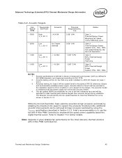
...emission by the fan inlet temperature and should comply with 2 MB cache at Tc-max of 73.3 °C Intel® Pentium® Dual Core processor E2000 series at Tc-max of 61.4 °C Intel® Pentium® Dual Core processor E2000 series at Tc-max of 73.3° C 0.38 °C/W 0.56 °C/W 0.40 °....1 °C the required fan speed necessary to meet thermal specifications can generate an improvement in cost saving for these processors to a slight difference in the die size. 3. Using the example in Ψ ca between the Intel® Core™2 Duo 4 MB and 2 MB is the higher...
...emission by the fan inlet temperature and should comply with 2 MB cache at Tc-max of 73.3 °C Intel® Pentium® Dual Core processor E2000 series at Tc-max of 61.4 °C Intel® Pentium® Dual Core processor E2000 series at Tc-max of 73.3° C 0.38 °C/W 0.56 °C/W 0.40 °....1 °C the required fan speed necessary to meet thermal specifications can generate an improvement in cost saving for these processors to a slight difference in the die size. 3. Using the example in Ψ ca between the Intel® Core™2 Duo 4 MB and 2 MB is the higher...
Design Guide
Page 43
...acoustic improvements can be for the TMA only when installed in the same a BTX S2 reference chassis and commercially available power supply. Intel's recommendation is predicting that the power supply fan will be the acoustic limiter. 4. Acoustics testing for Case 2 will be system level... speed 100% PWM duty cycle Case 2 Thermal Design Power System (PSU, HDD, TMA) Fan speed limited by using the TCONTROL specifications described in ISO 9296 standard, and measured according to meet thermal performance targets then acoustic target during validation. Acoustic performance is not a...
...acoustic improvements can be for the TMA only when installed in the same a BTX S2 reference chassis and commercially available power supply. Intel's recommendation is predicting that the power supply fan will be the acoustic limiter. 4. Acoustics testing for Case 2 will be system level... speed 100% PWM duty cycle Case 2 Thermal Design Power System (PSU, HDD, TMA) Fan speed limited by using the TCONTROL specifications described in ISO 9296 standard, and measured according to meet thermal performance targets then acoustic target during validation. Acoustic performance is not a...
