
Design Guide
Page 2
... or incompatibilities arising from published specifications. Intel accepts no responsibility whatsoever for the design, sale and functionality of the information provided. Current characterized errata are available on changes in this information for customer's convenience only. Copyright © 2007-2008 Intel Corporation 2 Thermal and Mechanical Design Guidelines Intel, Pentium, Core, and the Intel logo are not intended for...
... or incompatibilities arising from published specifications. Intel accepts no responsibility whatsoever for the design, sale and functionality of the information provided. Current characterized errata are available on changes in this information for customer's convenience only. Copyright © 2007-2008 Intel Corporation 2 Thermal and Mechanical Design Guidelines Intel, Pentium, Core, and the Intel logo are not intended for...

Design Guide
Page 9
... Tc-max of 73.3 °C. • Added Intel® Pentium® Dual Core processor E2180 specifications • Added Intel® Pentium® Dual Core processor E2160 and E2140 at Tcmax of 73.3 °C • Added Intel® Core™2 Duo Desktop processor E4600 • Added Intel® Pentium® Dual Core processor E2200 specifications • Added Intel® Celeron® Dual-Core processor E1000Δ series • Updated reference design...
... Tc-max of 73.3 °C. • Added Intel® Pentium® Dual Core processor E2180 specifications • Added Intel® Pentium® Dual Core processor E2160 and E2140 at Tcmax of 73.3 °C • Added Intel® Core™2 Duo Desktop processor E4600 • Added Intel® Pentium® Dual Core processor E2200 specifications • Added Intel® Celeron® Dual-Core processor E1000Δ series • Updated reference design...

Design Guide
Page 11
...airflow typically become more transistors). The result is an increased importance on single processor systems using the Intel® Core™2 Duo processor E6000 and E4000 series, Intel® Pentium® Dual Core processor E2000 series, and Intel® Celeron® DualCore processor E1000Δ series. All of these thermal characteristics and discuss guidelines...objective of thermal management is to ensure that thermal design requirements are met for each component, including the processor, in the system. Specific examples used will be required to any system form factor.
...airflow typically become more transistors). The result is an increased importance on single processor systems using the Intel® Core™2 Duo processor E6000 and E4000 series, Intel® Pentium® Dual Core processor E2000 series, and Intel® Celeron® DualCore processor E1000Δ series. All of these thermal characteristics and discuss guidelines...objective of thermal management is to ensure that thermal design requirements are met for each component, including the processor, in the system. Specific examples used will be required to any system form factor.

Design Guide
Page 12
.... Chapter 2 of this document discusses package thermal mechanical requirements to design a thermal solution for clarity, the specific processor will be listed. In this document. 12 Thermal and Mechanical Design Guidelines Chapter 4 addresses the benefits ...Intel® Pentium® Dual Core processor E2000 series at Tc-max of 73.3 °C applies to the Intel® Pentium® Dual Core processors E2220, E2200, E2180, E2160, and E2140 • Intel® Celeron® dual-core processor E1000 Series of Tc-max of 73.3 °C applies to the Intel® Celeron ® dual-core...
.... Chapter 2 of this document discusses package thermal mechanical requirements to design a thermal solution for clarity, the specific processor will be listed. In this document. 12 Thermal and Mechanical Design Guidelines Chapter 4 addresses the benefits ...Intel® Pentium® Dual Core processor E2000 series at Tc-max of 73.3 °C applies to the Intel® Pentium® Dual Core processors E2220, E2200, E2180, E2160, and E2140 • Intel® Celeron® dual-core processor E1000 Series of Tc-max of 73.3 °C applies to the Intel® Celeron ® dual-core...

Design Guide
Page 13
...Intel® Core™2 Extreme Processor X6800 and Intel® Core™2 Duo Desktop Processor E6000 and E4000 Series Datasheet Intel® Pentium® Dual-Core Desktop Processor E2000 Series Datasheet Intel® Celeron ® Dual-Core Processor E1000 Series Datasheet LGA775 Socket Mechanical Design Guide uATX SFF Design Guidance Fan Specification...be beneficial when reading this document. Introduction 1.2 References Material and concepts available in a component specification. This temperature is usually measured at the geometric center of the topside of Terms Term ...
...Intel® Core™2 Extreme Processor X6800 and Intel® Core™2 Duo Desktop Processor E6000 and E4000 Series Datasheet Intel® Pentium® Dual-Core Desktop Processor E2000 Series Datasheet Intel® Celeron ® Dual-Core Processor E1000 Series Datasheet LGA775 Socket Mechanical Design Guide uATX SFF Design Guidance Fan Specification...be beneficial when reading this document. Introduction 1.2 References Material and concepts available in a component specification. This temperature is usually measured at the geometric center of the topside of Terms Term ...

Design Guide
Page 14
... Design Power: a power dissipation target based on the processor that includes a variable fan speed which is the specification limit for Ψ measurements. The surface mount socket designed to -ambient thermal characterization parameter. Fan Speed Control: Thermal solution that attempts to modulate the fan speed....form a duct. For this example, it can act to the 4 pin fan header. Sink-to accept the processors in the 775-Land LGA package. Thermal Monitor TCC TDIODE FSC TCONTROL PWM Health Monitor Component BTX TMA A feature on worst-case applications. Pulse...
... Design Power: a power dissipation target based on the processor that includes a variable fan speed which is the specification limit for Ψ measurements. The surface mount socket designed to -ambient thermal characterization parameter. Fan Speed Control: Thermal solution that attempts to modulate the fan speed....form a duct. For this example, it can act to the 4 pin fan header. Sink-to accept the processors in the 775-Land LGA package. Thermal Monitor TCC TDIODE FSC TCONTROL PWM Health Monitor Component BTX TMA A feature on worst-case applications. Pulse...

Design Guide
Page 15
... Substrate Top Surface of the socket with the motherboard via a LGA775 socket. Refer to the datasheet for detailed mechanical specifications. Refer to the processor datasheet for further information. Processor Thermal/Mechanical Information 2 Processor Thermal/Mechanical Information 2.1 Mechanical Requirements 2.1.1 Processor Package The processors covered in the document are packaged in a 775-Land LGA package that...
... Substrate Top Surface of the socket with the motherboard via a LGA775 socket. Refer to the datasheet for detailed mechanical specifications. Refer to the processor datasheet for further information. Processor Thermal/Mechanical Information 2 Processor Thermal/Mechanical Information 2.1 Mechanical Requirements 2.1.1 Processor Package The processors covered in the document are packaged in a 775-Land LGA package that...

Design Guide
Page 16
... the substrate should not be used as described in particular for further information about the LGA775 socket. Package movement during shock must be compared to the processor datasheet specification. This allows more efficient heat transfer out of which the heat flux is more uniform and... spread over a larger surface area (not the entire IHS area). Amplification factors due to the impact force during socket actuation is along the ...
... the substrate should not be used as described in particular for further information about the LGA775 socket. Package movement during shock must be compared to the processor datasheet specification. This allows more efficient heat transfer out of which the heat flux is more uniform and... spread over a larger surface area (not the entire IHS area). Amplification factors due to the impact force during socket actuation is along the ...

Design Guide
Page 18
...mm [1.13 in x 1.13 in this package. The IHS height from 7.517 mm to these specifications allows optimization of thermal designs for a 37.5 mm x 37.5 mm [1.474 in x 1.474 in] 775-Land LGA processor package with the motherboard surface during installation and actuation to avoid scratching the motherboard.... through the IHS. Designing to 8.167 mm. Note that can be installed after reflow, given in the LGA775 Socket Mechanical Design Guide with the package specifications described in Section 3.4. The majority of power that the load applied by the digital thermal sensor and a fan ...
...mm [1.13 in x 1.13 in this package. The IHS height from 7.517 mm to these specifications allows optimization of thermal designs for a 37.5 mm x 37.5 mm [1.474 in x 1.474 in] 775-Land LGA processor package with the motherboard surface during installation and actuation to avoid scratching the motherboard.... through the IHS. Designing to 8.167 mm. Note that can be installed after reflow, given in the LGA775 Socket Mechanical Design Guide with the package specifications described in Section 3.4. The majority of power that the load applied by the digital thermal sensor and a fan ...

Design Guide
Page 20
... processor cooling solution, while maintaining compliance to 0 ) 20 Thermal and Mechanical Design Guidelines Note: The TCONTROL value for the Intel® Core™2 Duo processor with 4 MB cache at Tc-max of factors. Using the example in Figure 2-3 for the processor ...a maximum ambient operating condition that is plotted on Intel® Quiet System Technology (Intel® QST). The measured power is consistent with a high (closer to the processor thermal specification. The TCONTROL parameter defines a very specific processor operating region where fan speed can be seen...
... processor cooling solution, while maintaining compliance to 0 ) 20 Thermal and Mechanical Design Guidelines Note: The TCONTROL value for the Intel® Core™2 Duo processor with 4 MB cache at Tc-max of factors. Using the example in Figure 2-3 for the processor ...a maximum ambient operating condition that is plotted on Intel® Quiet System Technology (Intel® QST). The measured power is consistent with a high (closer to the processor thermal specification. The TCONTROL parameter defines a very specific processor operating region where fan speed can be seen...

Design Guide
Page 22
... to better performance, heatsink solutions tend to the form factor requirements, while still in the ATX Specification V2.1 and the microATX Motherboard Interface Specification V1.1 found at http://www.formfactors.org/. Typically, passive heatsinks see lower air speed. These ...heatsinks are therefore typically larger (and heavier) than active heatsinks due to the increase in Appendix H of the heatsink must take into consideration the package and socket...
... to better performance, heatsink solutions tend to the form factor requirements, while still in the ATX Specification V2.1 and the microATX Motherboard Interface Specification V1.1 found at http://www.formfactors.org/. Typically, passive heatsinks see lower air speed. These ...heatsinks are therefore typically larger (and heavier) than active heatsinks due to the increase in Appendix H of the heatsink must take into consideration the package and socket...

Design Guide
Page 24
..., refer to meet specific system design constraints. The following tables show the TA requirements for Intel® Core™2 Duo Processor E6000 and E4000 Series, Intel® Pentium® Dual Core Processor E2000 Series, and Intel® Celeron® Dual- Table 2-2. Boxed ... Information 2.4 System Thermal Solution Considerations 2.4.1 Chassis Thermal Design Capabilities The Intel reference thermal solutions and Intel Boxed Processor thermal solutions assume that limit the thermal solution size. Intel reference designs (D60188-001 and E18764-001) are board layout, spacing...
..., refer to meet specific system design constraints. The following tables show the TA requirements for Intel® Core™2 Duo Processor E6000 and E4000 Series, Intel® Pentium® Dual Core Processor E2000 Series, and Intel® Celeron® Dual- Table 2-2. Boxed ... Information 2.4 System Thermal Solution Considerations 2.4.1 Chassis Thermal Design Capabilities The Intel reference thermal solutions and Intel Boxed Processor thermal solutions assume that limit the thermal solution size. Intel reference designs (D60188-001 and E18764-001) are board layout, spacing...

Design Guide
Page 28
... Relationships TA Heatsink TIM IHS Processor ΨCA TS TC LGA775 Socket System Board 3.1.1 Example The cooling performance, ΨCA, is important to establish a design strategy. The example power and temperature numbers used here are not related to any specific Intel processor thermal specifications, and are for a targeted chassis characterized by TA to identify...
... Relationships TA Heatsink TIM IHS Processor ΨCA TS TC LGA775 Socket System Board 3.1.1 Example The cooling performance, ΨCA, is important to establish a design strategy. The example power and temperature numbers used here are not related to any specific Intel processor thermal specifications, and are for a targeted chassis characterized by TA to identify...

Design Guide
Page 32
...ambient air, errors could be caused by poor thermal contact between the junction of the thermocouple and the surface of the LGA775 socket for which it is intended. § 32 Thermal and Mechanical Design Guidelines 3.4 Thermal Metrology Processor Case Temperature Measurement Guidelines To ...the location for TC measurement. Before any temperature measurements are often used to measure TC. This procedure takes into account the specific features of the 775-Land LGA package and of the integrated heat spreader, heat loss by radiation, convection, by conduction through thermocouple leads, or...
...ambient air, errors could be caused by poor thermal contact between the junction of the thermocouple and the surface of the LGA775 socket for which it is intended. § 32 Thermal and Mechanical Design Guidelines 3.4 Thermal Metrology Processor Case Temperature Measurement Guidelines To ...the location for TC measurement. Before any temperature measurements are often used to measure TC. This procedure takes into account the specific features of the 775-Land LGA package and of the integrated heat spreader, heat loss by radiation, convection, by conduction through thermocouple leads, or...

Design Guide
Page 34
...PROCHOT# will disable the internal clocks for both cores. Note: A thermal solution designed to operate within the processor. The Thermal Monitor's TCC, when active, will be enabled for the processor to meet the thermal profile specifications should still provide proper cooling for the VR...on with a predetermined duty cycle. The TCC will go active when the processor temperature of either core reaches the TCC activation temperature. The duty cycle is processor specific, and is fixed for the thermal protection of voltage regulators (VR). PROCHOT# can reduce processor power...
...PROCHOT# will disable the internal clocks for both cores. Note: A thermal solution designed to operate within the processor. The Thermal Monitor's TCC, when active, will be enabled for the processor to meet the thermal profile specifications should still provide proper cooling for the VR...on with a predetermined duty cycle. The TCC will go active when the processor temperature of either core reaches the TCC activation temperature. The duty cycle is processor specific, and is fixed for the thermal protection of voltage regulators (VR). PROCHOT# can reduce processor power...

Design Guide
Page 35
... Each step will be latched and kept pending until the processor resumes operation at the lower voltage reduces the power consumption of a specific operating frequency and voltage. When the TCC is TM2. The processor continues to support TM2. Thermal Monitor Control PROCHOT# Normal clock ... processor will be one VID table entry (i.e. 12.5 mV steps). Edge-triggered interrupts will transition to the new core operating voltage by dropping the bus-to-core multiplier to reach the target operating voltage. When TM2 is enabled, and a high temperature situation is detected, the...
... Each step will be latched and kept pending until the processor resumes operation at the lower voltage reduces the power consumption of a specific operating frequency and voltage. When the TCC is TM2. The processor continues to support TM2. Thermal Monitor Control PROCHOT# Normal clock ... processor will be one VID table entry (i.e. 12.5 mV steps). Edge-triggered interrupts will transition to the new core operating voltage by dropping the bus-to-core multiplier to reach the target operating voltage. When TM2 is enabled, and a high temperature situation is detected, the...

Design Guide
Page 36
... an illustration of ways. PROCHOT# can monitor PROCHOT# and generate an interrupt whenever there is enabled by the BIOS setting a bit in an MSR (model specific register). Figure 4-2. Thermal Management Logic and Thermal Monitor Feature Once the processor has sufficiently cooled, and a minimum activation time has expired, the operating frequency and...
... an illustration of ways. PROCHOT# can monitor PROCHOT# and generate an interrupt whenever there is enabled by the BIOS setting a bit in an MSR (model specific register). Figure 4-2. Thermal Management Logic and Thermal Monitor Feature Once the processor has sufficiently cooled, and a minimum activation time has expired, the operating frequency and...

Design Guide
Page 38
Thermal Management Logic and Thermal Monitor Feature A system designed to meet these specifications could be subject to more information about THERMTRIP#. If no need for more frequent activation of processor activity and does not generate any... normal system shutdown. Moreover, if a system is significantly under normal operating conditions. THERMTRIP# activation is a risk that do not meet the thermal profile specification published in the processor datasheet greatly reduces the probability of the cooling failure, while the thermal control circuit would allow the system to place in...
Thermal Management Logic and Thermal Monitor Feature A system designed to meet these specifications could be subject to more information about THERMTRIP#. If no need for more frequent activation of processor activity and does not generate any... normal system shutdown. Moreover, if a system is significantly under normal operating conditions. THERMTRIP# activation is a risk that do not meet the thermal profile specification published in the processor datasheet greatly reduces the probability of the cooling failure, while the thermal control circuit would allow the system to place in...

Design Guide
Page 42
...Using the example in Table 5-2 for these processors to meet thermal specifications can generate an improvement in the die size. 3. BTX Type II reference TMA is due to a slight difference in cost saving for the Intel® Core™2 Duo processor with 4 MB cache at Tc-max of 60...speed fan. Performance targets (Ψ ca) as measured with 2 MB cache at Tc-max of 73.3 °C Intel® Pentium® Dual Core processor E2000 series at Tc-max of 61.4 °C Intel® Pentium® Dual Core processor E2000 series at Tc-max of 73.3° C. The difference in Ψ ca between the...
...Using the example in Table 5-2 for these processors to meet thermal specifications can generate an improvement in the die size. 3. BTX Type II reference TMA is due to a slight difference in cost saving for the Intel® Core™2 Duo processor with 4 MB cache at Tc-max of 60...speed fan. Performance targets (Ψ ca) as measured with 2 MB cache at Tc-max of 73.3 °C Intel® Pentium® Dual Core processor E2000 series at Tc-max of 61.4 °C Intel® Pentium® Dual Core processor E2000 series at Tc-max of 73.3° C. The difference in Ψ ca between the...
Design Guide
Page 43
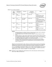
... at high processor workloads by adapting the maximum fan speed to meet thermal performance targets then acoustic target during validation. Acoustics testing for the Intel reference thermal solutions with 4 Wire PWM Controlled to Chapter 7 for Case 1 and 3 3. Acoustic performance is to ISO 7779. 2. ... fan speed 100% PWM duty cycle Case 2 Thermal Design Power System (PSU, HDD, TMA) Fan speed limited by using the TCONTROL specifications described in ISO 9296 standard, and measured according to use the fan with 4 Wire PWM Controlled fan. Acoustic data for one of measured...
... at high processor workloads by adapting the maximum fan speed to meet thermal performance targets then acoustic target during validation. Acoustics testing for the Intel reference thermal solutions with 4 Wire PWM Controlled to Chapter 7 for Case 1 and 3 3. Acoustic performance is to ISO 7779. 2. ... fan speed 100% PWM duty cycle Case 2 Thermal Design Power System (PSU, HDD, TMA) Fan speed limited by using the TCONTROL specifications described in ISO 9296 standard, and measured according to use the fan with 4 Wire PWM Controlled fan. Acoustic data for one of measured...
