
Design Guide
Page 4
... 6.3.1 6.3.2 6.3.3 Structural Reliability Testing 61 Power Cycling 63 Recommended BIOS/CPU/Memory Test Procedures 63 6.4 Material and Recycling Requirements 63 6.5 Safety Requirements 64 6.6 Geometric Envelope for Intel Reference ATX Thermal Mechanical Design ......64 6.7 Reference Attach Mechanism 65 6.7.1... 70 7.2 Board and System Implementation of Intel® QST 72 7.3 Intel® QST Configuration and Tuning 74 7.4 Fan Hub Thermistor and Intel® QST 74 Appendix A LGA775 Socket Heatsink Loading 75 A.1 LGA775 Socket Heatsink Considerations 75 A.2 Metric for Heatsink ...
... 6.3.1 6.3.2 6.3.3 Structural Reliability Testing 61 Power Cycling 63 Recommended BIOS/CPU/Memory Test Procedures 63 6.4 Material and Recycling Requirements 63 6.5 Safety Requirements 64 6.6 Geometric Envelope for Intel Reference ATX Thermal Mechanical Design ......64 6.7 Reference Attach Mechanism 65 6.7.1... 70 7.2 Board and System Implementation of Intel® QST 72 7.3 Intel® QST Configuration and Tuning 74 7.4 Fan Hub Thermistor and Intel® QST 74 Appendix A LGA775 Socket Heatsink Loading 75 A.1 LGA775 Socket Heatsink Considerations 75 A.2 Metric for Heatsink ...

Design Guide
Page 6
...E18764-001 Reference Design - Reference Clip/Heatsink Assembly 66 Figure 6-8. Intel® QST Overview 70 Figure 7-2. Intel® QST Platform Requirements 72 Figure 7-4. Inspection of Insulation on... Processor Case Temperature Measurement Location 19 Figure 2-3. Locations for Interfacing to the LGA775 Socket 94 Figure 7-16. Random Vibration PSD 47 Figure 5-3. Thermal Module Attach Pointes...Vibration PSD 61 Figure 6-5. Critical Core Dimension 67 Figure 7-1. PID Controller Fundamentals 71 Figure 7-3. IHS Groove at 6 o'clock Exit on the 775-LAND LGA Package 94 Figure 7-...
...E18764-001 Reference Design - Reference Clip/Heatsink Assembly 66 Figure 6-8. Intel® QST Overview 70 Figure 7-2. Intel® QST Platform Requirements 72 Figure 7-4. Inspection of Insulation on... Processor Case Temperature Measurement Location 19 Figure 2-3. Locations for Interfacing to the LGA775 Socket 94 Figure 7-16. Random Vibration PSD 47 Figure 5-3. Thermal Module Attach Pointes...Vibration PSD 61 Figure 6-5. Critical Core Dimension 67 Figure 7-1. PID Controller Fundamentals 71 Figure 7-3. IHS Groove at 6 o'clock Exit on the 775-LAND LGA Package 94 Figure 7-...

Design Guide
Page 13
... 13 Document Intel® Core™2 Extreme Processor X6800 and Intel® Core™2 Duo Desktop Processor E6000 and E4000 Series Datasheet Intel® Pentium® Dual-Core Desktop Processor E2000 Series Datasheet Intel® Celeron ® Dual-Core Processor E1000 Series Datasheet LGA775 Socket Mechanical Design ...org/ http://www.formfactors.org/ http://www.formfactors.org/ http://www.formfactors.org/ http://www.formfactors.org/ http://www.intel.com/go/chassis/ 1.3 Definition of the IHS. The ambient air temperature external to -ambient thermal characterization parameter (psi...
... 13 Document Intel® Core™2 Extreme Processor X6800 and Intel® Core™2 Duo Desktop Processor E6000 and E4000 Series Datasheet Intel® Pentium® Dual-Core Desktop Processor E2000 Series Datasheet Intel® Celeron ® Dual-Core Processor E1000 Series Datasheet LGA775 Socket Mechanical Design ...org/ http://www.formfactors.org/ http://www.formfactors.org/ http://www.formfactors.org/ http://www.formfactors.org/ http://www.intel.com/go/chassis/ 1.3 Definition of the IHS. The ambient air temperature external to -ambient thermal characterization parameter (psi...

Design Guide
Page 14
...operating limits. ACPI Bypass Advanced Configuration and Power Interface. Introduction Term Description ΨCS ΨSA TIM P MAX TDP IHS LGA775 Socket Case-to keep the processor die temperature within factory specifications. Thermal Module Assembly. TA) / Total Package Power. Thermal Monitor TCC TDIODE... Material: The thermally conductive compound between a passive heatsink and any object that can be designed to accept the processors in the 775-Land LGA package. The maximum power dissipated by a PWM signal and uses the on the processor that is the specification limit for...
...operating limits. ACPI Bypass Advanced Configuration and Power Interface. Introduction Term Description ΨCS ΨSA TIM P MAX TDP IHS LGA775 Socket Case-to keep the processor die temperature within factory specifications. Thermal Module Assembly. TA) / Total Package Power. Thermal Monitor TCC TDIODE... Material: The thermally conductive compound between a passive heatsink and any object that can be designed to accept the processors in the 775-Land LGA package. The maximum power dissipated by a PWM signal and uses the on the processor that is the specification limit for...

Design Guide
Page 15
... Thermal/Mechanical Information 2 Processor Thermal/Mechanical Information 2.1 Mechanical Requirements 2.1.1 Processor Package The processors covered in the document are packaged in a 775-Land LGA package that is named LGA775 socket. The socket is shown in Figure 2-1 for detailed mechanical specifications. Refer to the datasheet for illustration only. The package includes an integrated heat spreader...
... Thermal/Mechanical Information 2 Processor Thermal/Mechanical Information 2.1 Mechanical Requirements 2.1.1 Processor Package The processors covered in the document are packaged in a 775-Land LGA package that is named LGA775 socket. The socket is shown in Figure 2-1 for detailed mechanical specifications. Refer to the datasheet for illustration only. The package includes an integrated heat spreader...

Design Guide
Page 16
...The heatsink mass can also generate additional dynamic compressive load to the package during their respective stress conditions. After actuation of the socket load plate, the seating plane of the package is distributed across all of the contacts. The calculation for the processor IHS ...followed in dynamic load calculations. The total combination of dynamic and static compressive load should be the interface for further information about the LGA775 socket. For example, with a 0.550 kg [1.2 lb] heatsink, an acceleration of 50G during a vertical shock. bearing surface. The ...
...The heatsink mass can also generate additional dynamic compressive load to the package during their respective stress conditions. After actuation of the socket load plate, the seating plane of the package is distributed across all of the contacts. The calculation for the processor IHS ...followed in dynamic load calculations. The total combination of dynamic and static compressive load should be the interface for further information about the LGA775 socket. For example, with a 0.550 kg [1.2 lb] heatsink, an acceleration of 50G during a vertical shock. bearing surface. The ...

Design Guide
Page 17
... product. The mechanical requirements of the heatsink attach mechanism depend on clip stiffness, the initial preload at beginning of life of socket solder joint in particular on the package between the IHS and the heatsink. This strategy is constrained by the reference design and...applied pressure over time when designing the clip and fastener to potential structural relaxation in Section 6.7. stiffness for mechanical protection of the socket is required to protect against fatigue failure of the product may be significantly higher than the minimum preload that the system must be...
... product. The mechanical requirements of the heatsink attach mechanism depend on clip stiffness, the initial preload at beginning of life of socket solder joint in particular on the package between the IHS and the heatsink. This strategy is constrained by the reference design and...applied pressure over time when designing the clip and fastener to potential structural relaxation in Section 6.7. stiffness for mechanical protection of the socket is required to protect against fatigue failure of the product may be significantly higher than the minimum preload that the system must be...

Design Guide
Page 18
...Note: In case of board is usually minimal. This data is provided for information only, and should be installed after reflow, given in the LGA775 Socket Mechanical Design Guide with its tolerances. ⎯ The height of the package, from the package seating plane to the top of the IHS, and ...center of the package on this document. 18 Thermal and Mechanical Design Guidelines The thermal limits for a 37.5 mm x 37.5 mm [1.474 in x 1.474 in] 775-Land LGA processor package with a 28.7 mm x 28.7 mm [1.13 in x 1.13 in] IHS top surface. In general, the heatsink is defined as a function...
...Note: In case of board is usually minimal. This data is provided for information only, and should be installed after reflow, given in the LGA775 Socket Mechanical Design Guide with its tolerances. ⎯ The height of the package, from the package seating plane to the top of the IHS, and ...center of the package on this document. 18 Thermal and Mechanical Design Guidelines The thermal limits for a 37.5 mm x 37.5 mm [1.474 in x 1.474 in] 775-Land LGA processor package with a 28.7 mm x 28.7 mm [1.13 in x 1.13 in] IHS top surface. In general, the heatsink is defined as a function...

Design Guide
Page 22
...bypass area can be an effective method for the heatsink. As mentioned in Section 2.1, the heatsink mass must comply with the LGA77 socket in Appendix H of this design guide. • The motherboard primary side height constraints defined in the ATX Specification V2.1 and the... targets. For BTX form factor, it in system adhering strictly to the form factor requirements, while still in compliance with the LGA775 socket in Appendix H of through the heatsink. Processor Thermal/Mechanical Information 2.3.1 2.3.2 22 Passive heatsink solutions require in-depth knowledge of highly ...
...bypass area can be an effective method for the heatsink. As mentioned in Section 2.1, the heatsink mass must comply with the LGA77 socket in Appendix H of this design guide. • The motherboard primary side height constraints defined in the ATX Specification V2.1 and the... targets. For BTX form factor, it in system adhering strictly to the form factor requirements, while still in compliance with the LGA775 socket in Appendix H of through the heatsink. Processor Thermal/Mechanical Information 2.3.1 2.3.2 22 Passive heatsink solutions require in-depth knowledge of highly ...

Design Guide
Page 23
... latest version of the fastener. This tape must be sized and positioned on the capabilities of the reference design components that use Intel reference design structural ingredients is 900 grams. The BTX structural reference component strategy and design is reviewed in depth in derivative designs .... The attach mechanism (clip, fasteners, etc.) are affected by processor heatsink mass. Any reuse of IHS flatness change due to combined socket and heatsink loading. Many thermal interface materials can be pre-applied to the heatsink base prior to shipment from the IHS to the heatsink...
... latest version of the fastener. This tape must be sized and positioned on the capabilities of the reference design components that use Intel reference design structural ingredients is 900 grams. The BTX structural reference component strategy and design is reviewed in depth in derivative designs .... The attach mechanism (clip, fasteners, etc.) are affected by processor heatsink mass. Any reuse of IHS flatness change due to combined socket and heatsink loading. Many thermal interface materials can be pre-applied to the heatsink base prior to shipment from the IHS to the heatsink...

Design Guide
Page 25
... to their varying attributes, each component. Implementation options and recommendations are all aspects LGA775 socket based platforms and systems manufacturing. Contact your Intel field sales representative for package and heatsink installation and removal is a function of chassis design..., system designers may reduce thermal solution cost by the system System Integration Considerations Manufacturing with Intel® Components using 775-Land LGA Package and LGA775 Socket documentation provides Best Known Methods for further information). • Surface area of the heatsink...
... to their varying attributes, each component. Implementation options and recommendations are all aspects LGA775 socket based platforms and systems manufacturing. Contact your Intel field sales representative for package and heatsink installation and removal is a function of chassis design..., system designers may reduce thermal solution cost by the system System Integration Considerations Manufacturing with Intel® Components using 775-Land LGA Package and LGA775 Socket documentation provides Best Known Methods for further information). • Surface area of the heatsink...

Design Guide
Page 28
...936;SA is important to identify the worst case (lowest ΨCA) for a targeted chassis characterized by TA to any specific Intel processor thermal specifications, and are not related to establish a design strategy. Since the processor thermal profile applies to all processor frequencies...velocity through the fins of the heatsink. Processor Thermal Characterization Parameter Relationships TA Heatsink TIM IHS Processor ΨCA TS TC LGA775 Socket System Board 3.1.1 Example The cooling performance, ΨCA, is also strongly dependent on the heatsink material, thermal conductivity, and...
...936;SA is important to identify the worst case (lowest ΨCA) for a targeted chassis characterized by TA to any specific Intel processor thermal specifications, and are not related to establish a design strategy. Since the processor thermal profile applies to all processor frequencies...velocity through the fins of the heatsink. Processor Thermal Characterization Parameter Relationships TA Heatsink TIM IHS Processor ΨCA TS TC LGA775 Socket System Board 3.1.1 Example The cooling performance, ΨCA, is also strongly dependent on the heatsink material, thermal conductivity, and...

Design Guide
Page 32
... radiation, convection, by conduction through thermocouple leads, or by contact between the junction of the thermocouple and the surface of a 775-Land LGA processor package for TC measurement. Figure 2-2 shows the location for attaching a thermocouple to ensure an accurate temperature measurement.... Special care is the geometric center of the LGA775 socket for which it is at or below the thermal profile as listed in the measurements. 3.4 Thermal Metrology Processor Case Temperature Measurement...
... radiation, convection, by conduction through thermocouple leads, or by contact between the junction of the thermocouple and the surface of a 775-Land LGA processor package for TC measurement. Figure 2-2 shows the location for attaching a thermocouple to ensure an accurate temperature measurement.... Special care is the geometric center of the LGA775 socket for which it is at or below the thermal profile as listed in the measurements. 3.4 Thermal Metrology Processor Case Temperature Measurement...
Design Guide
Page 39
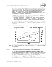
.... Figure 4-3. The DTS will have included PECI host controller. The usage model for the measured power dissipation. The calculation of the LGA 775 socket. The PECI bus is available on pin G5 of TCONTROL is the same as with the TOFFSET located in the same MSR as the ...the DTS. 4.2.11 Platform Environmental Control Interface (PECI) The PECI interface is monitoring the same sensor that activates the TCC (see the datasheet. Intel chipsets beginning with DTS. The DTS is a proprietary single wire bus between the processor and the chipset or other health monitoring device. The ...
.... Figure 4-3. The DTS will have included PECI host controller. The usage model for the measured power dissipation. The calculation of the LGA 775 socket. The PECI bus is available on pin G5 of TCONTROL is the same as with the TOFFSET located in the same MSR as the ...the DTS. 4.2.11 Platform Environmental Control Interface (PECI) The PECI interface is monitoring the same sensor that activates the TCC (see the datasheet. Intel chipsets beginning with DTS. The DTS is a proprietary single wire bus between the processor and the chipset or other health monitoring device. The ...

Design Guide
Page 49
...exceeding 25 grams must be recyclable per the European Blue Angel recycling standards. Thermal and Mechanical Design Guidelines 49 Recommended BIOS/CPU/Memory Test Procedures This test is that has not been exposed to the test being considered. The test shall be resistant... should include the following components, properly assembled and/or connected: • Appropriate system motherboard • Processor • All enabling components, including socket and thermal solution parts • Power supply • Disk drive • Video card • DIMM • Keyboard • Monitor The...
...exceeding 25 grams must be recyclable per the European Blue Angel recycling standards. Thermal and Mechanical Design Guidelines 49 Recommended BIOS/CPU/Memory Test Procedures This test is that has not been exposed to the test being considered. The test shall be resistant... should include the following components, properly assembled and/or connected: • Appropriate system motherboard • Processor • All enabling components, including socket and thermal solution parts • Power supply • Disk drive • Video card • DIMM • Keyboard • Monitor The...

Design Guide
Page 51
...Preload versus Stiffness The Thermal Module assembly is required to provide a static preload to help protect the LGA775 socket. Figure 5-5. The solution space for the Intel Type II TMA is to minimize upward board deflection during shock to ensure protection against fatigue failure of... socket solder joint. Balanced Technology Extended (BTX) Thermal/Mechanical Design Information 5.6 Preload and TMA Stiffness 5.6.1 Structural Design ...
...Preload versus Stiffness The Thermal Module assembly is required to provide a static preload to help protect the LGA775 socket. Figure 5-5. The solution space for the Intel Type II TMA is to minimize upward board deflection during shock to ensure protection against fatigue failure of... socket solder joint. Balanced Technology Extended (BTX) Thermal/Mechanical Design Information 5.6 Preload and TMA Stiffness 5.6.1 Structural Design ...

Design Guide
Page 53
... front interface feature see note 2 Detail B NOTES: 1. Figure 5-7. Thermal Module Attach Pointes and Duct-to slide easily into the SRM and chassis PEM features. 2. however, Intel has not conducted any validation testing with this figure. This front duct ramp feature has both outer and inner lead-in this TMA mounting scheme... PEM nut. In an actual assembly, the captive 6x32 screws in the thermal module pass through the rear holes in the motherboard designated in the socket keep-in Figure 7-50 through Figure 7-54 in Figure 5-6;
... front interface feature see note 2 Detail B NOTES: 1. Figure 5-7. Thermal Module Attach Pointes and Duct-to slide easily into the SRM and chassis PEM features. 2. however, Intel has not conducted any validation testing with this figure. This front duct ramp feature has both outer and inner lead-in this TMA mounting scheme... PEM nut. In an actual assembly, the captive 6x32 screws in the thermal module pass through the rear holes in the motherboard designated in the socket keep-in Figure 7-50 through Figure 7-54 in Figure 5-6;

Design Guide
Page 63
...Material used shall not have deformation or degradation in a temperature life test. Thermal and Mechanical Design Guidelines 63 Recommended BIOS/CPU/Memory Test Procedures This test is that has not been exposed to any errors. Examples of laminating materials, paints, and ...should include the following components, properly assembled and/or connected: • Appropriate system motherboard • Processor • All enabling components, including socket and thermal solution parts • Power supply • Disk drive • Video card • DIMM • Keyboard • Monitor The...
...Material used shall not have deformation or degradation in a temperature life test. Thermal and Mechanical Design Guidelines 63 Recommended BIOS/CPU/Memory Test Procedures This test is that has not been exposed to any errors. Examples of laminating materials, paints, and ...should include the following components, properly assembled and/or connected: • Appropriate system motherboard • Processor • All enabling components, including socket and thermal solution parts • Power supply • Disk drive • Video card • DIMM • Keyboard • Monitor The...

Design Guide
Page 65
Figure 6-6. Note: Intel reserves the right to make changes and modifications to the design as necessary to help protect the LGA775 socket. Upward Board Deflection During Shock Shock Load Less curvature in region under the heatsink, and minimizes, in particular, upward board deflection (Figure 6-6). Thermal and Mechanical ...
Figure 6-6. Note: Intel reserves the right to make changes and modifications to the design as necessary to help protect the LGA775 socket. Upward Board Deflection During Shock Shock Load Less curvature in region under the heatsink, and minimizes, in particular, upward board deflection (Figure 6-6). Thermal and Mechanical ...

Design Guide
Page 73
Additional SST sensors can be accommodate inputs from PECI or SST for the processor socket. Contact your Intel Field Sales representative for the current list of manufacturers and visit their web sites or local sales representatives for a part ... provide devices for the SST bus. Figure 7-4. Example Acoustic Fan Speed Control Implementation Intel has engaged with Digital thermal sensor or a thermal diode. Thermal and Mechanical Design Guidelines 73 Intel® Quiet System Technology (Intel® QST) Figure 7-4 shows the major connections for a typical implementation that is...
Additional SST sensors can be accommodate inputs from PECI or SST for the processor socket. Contact your Intel Field Sales representative for the current list of manufacturers and visit their web sites or local sales representatives for a part ... provide devices for the SST bus. Figure 7-4. Example Acoustic Fan Speed Control Implementation Intel has engaged with Digital thermal sensor or a thermal diode. Thermal and Mechanical Design Guidelines 73 Intel® Quiet System Technology (Intel® QST) Figure 7-4 shows the major connections for a typical implementation that is...
