
Design Guide
Page 1
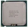
Intel® Celeron® Dual-Core Processor E1000Δ Series December 2008 Document Number: 317804-010 Intel® Pentium® Dual Core Processor E2000 Δ Series - Intel® Core™2 Duo Processor E6000 Δ and E4000 Δ Series - Intel® Core™2 Duo Processor, Intel® Pentium® Dual Core Processor, and Intel® Celeron® Dual-Core Processor Thermal and Mechanical Design Guidelines Supporting the: -
Intel® Celeron® Dual-Core Processor E1000Δ Series December 2008 Document Number: 317804-010 Intel® Pentium® Dual Core Processor E2000 Δ Series - Intel® Core™2 Duo Processor E6000 Δ and E4000 Δ Series - Intel® Core™2 Duo Processor, Intel® Pentium® Dual Core Processor, and Intel® Celeron® Dual-Core Processor Thermal and Mechanical Design Guidelines Supporting the: -

Design Guide
Page 2
... license, express or implied, by visiting http://www.intel.com . Intel Corporation may contain design defects or errors known as the property of Intel Corporation in any particular feature. The furnishing of its business operations. The Intel® Core™2 Duo processor, Intel® Pentium® Dual Core processor and Intel® Pentium® 4 processor may have no liability for the design, sale and...
... license, express or implied, by visiting http://www.intel.com . Intel Corporation may contain design defects or errors known as the property of Intel Corporation in any particular feature. The furnishing of its business operations. The Intel® Core™2 Duo processor, Intel® Pentium® Dual Core processor and Intel® Pentium® 4 processor may have no liability for the design, sale and...

Design Guide
Page 3
... 1.1.1 1.1.2 1.1.3 Importance of Thermal Management 11 Document Goals 11 Document Scope 12 1.2 References 13 1.3 Definition of Terms 13 2 Processor Thermal/Mechanical Information 15 2.1 Mechanical Requirements 15 2.1.1 Processor Package 15 2.1.2 Heatsink Attach 17 2.2 Thermal Requirements 18 2.2.1 Processor Case Temperature 18 2.2.2 Thermal Profile 19 2.2.3 TCONTROL 20 2.3 Heatsink Design Considerations 21 2.3.1 Heatsink Size 22 2.3.2 Heatsink Mass 22...
... 1.1.1 1.1.2 1.1.3 Importance of Thermal Management 11 Document Goals 11 Document Scope 12 1.2 References 13 1.3 Definition of Terms 13 2 Processor Thermal/Mechanical Information 15 2.1 Mechanical Requirements 15 2.1.1 Processor Package 15 2.1.2 Heatsink Attach 17 2.2 Thermal Requirements 18 2.2.1 Processor Case Temperature 18 2.2.2 Thermal Profile 19 2.2.3 TCONTROL 20 2.3 Heatsink Design Considerations 21 2.3.1 Heatsink Size 22 2.3.2 Heatsink Mass 22...

Design Guide
Page 6
...5-2. Position Bead on the 775-LAND LGA Package 94 Figure 7-15. Processor Case Temperature Measurement Location 19 Figure 2-3. Bottom View of Insulation on Thermocouple 95 Figure 7-17. Intel® QST Overview 70 ... to Attach .........96 Figure 7-19. Thermal Module Attach Pointes and Duct-to the LGA775 Socket 94 Figure 7-16. Exploded View 56 Figure 6-2. Exploded View 57 Figure 6-3. Random Vibration...at 3 o'clock Exit (Old Drawing 93 Figure 7-14. Inspection of Copper Core Applied by TC-1996 Grease 57 Figure 6-4. Bending the Tip of the Thermocouple 96 Figure 7-...
...5-2. Position Bead on the 775-LAND LGA Package 94 Figure 7-15. Processor Case Temperature Measurement Location 19 Figure 2-3. Bottom View of Insulation on Thermocouple 95 Figure 7-17. Intel® QST Overview 70 ... to Attach .........96 Figure 7-19. Thermal Module Attach Pointes and Duct-to the LGA775 Socket 94 Figure 7-16. Exploded View 56 Figure 6-2. Exploded View 57 Figure 6-3. Random Vibration...at 3 o'clock Exit (Old Drawing 93 Figure 7-14. Inspection of Copper Core Applied by TC-1996 Grease 57 Figure 6-4. Bending the Tip of the Thermocouple 96 Figure 7-...

Design Guide
Page 8
Heatsink Inlet Temperature of Intel Reference Thermal Solutions............24 Table 2-2. Processor Preload Limits 52 Table 6-1. D60188-001 Reference Heatsink Performance 58 Table 6-2. Typical Test Equipment 84 Table 7-3. D60188-001...2-1. Acoustic Results for Licensing Information of BTX Reference Design 146 Table 7-8. Fan Electrical Performance Requirements 125 Table 7-7. Heatsink Inlet Temperature of Intel Boxed Processor Thermal Solutions...24 Table 5-1. Acoustic Targets 43 Table 5-3. Acoustic Results for ATX Reference Heatsink (D60188-001 59 Table 6-4. ATX FSC Settings ...
Heatsink Inlet Temperature of Intel Reference Thermal Solutions............24 Table 2-2. Processor Preload Limits 52 Table 6-1. D60188-001 Reference Heatsink Performance 58 Table 6-2. Typical Test Equipment 84 Table 7-3. D60188-001...2-1. Acoustic Results for Licensing Information of BTX Reference Design 146 Table 7-8. Fan Electrical Performance Requirements 125 Table 7-7. Heatsink Inlet Temperature of Intel Boxed Processor Thermal Solutions...24 Table 5-1. Acoustic Targets 43 Table 5-3. Acoustic Results for ATX Reference Heatsink (D60188-001 59 Table 6-4. ATX FSC Settings ...

Design Guide
Page 9
.... • Added Intel® Core™2 Duo Desktop processor E4400 at Tc-max of 73.3 °C. • Added Intel® Pentium® Dual Core processor E2180 specifications • Added Intel® Pentium® Dual Core processor E2160 and E2140 at Tcmax of 73.3 °C • Added Intel® Core™2 Duo Desktop processor E4600 • Added Intel® Pentium® Dual Core processor E2200 specifications • Added Intel® Celeron® Dual-Core processor E1000Δ...
.... • Added Intel® Core™2 Duo Desktop processor E4400 at Tc-max of 73.3 °C. • Added Intel® Pentium® Dual Core processor E2180 specifications • Added Intel® Pentium® Dual Core processor E2160 and E2140 at Tcmax of 73.3 °C • Added Intel® Core™2 Duo Desktop processor E4600 • Added Intel® Pentium® Dual Core processor E2200 specifications • Added Intel® Celeron® Dual-Core processor E1000Δ...

Design Guide
Page 11
... and/or system damage. The processor temperature depends in particular on single processor systems using the Intel® Core™2 Duo processor E6000 and E4000 series, Intel® Pentium® Dual Core processor E2000 series, and Intel® Celeron® DualCore processor E1000Δ series. The result... this component. In a system environment, the processor temperature is expected to design a thermal solution for each component, including the processor, in the operating characteristics of a component may be the Intel enabled reference solution for ATX/uATX systems. See...
... and/or system damage. The processor temperature depends in particular on single processor systems using the Intel® Core™2 Duo processor E6000 and E4000 series, Intel® Pentium® Dual Core processor E2000 series, and Intel® Celeron® DualCore processor E1000Δ series. The result... this component. In a system environment, the processor temperature is expected to design a thermal solution for each component, including the processor, in the operating characteristics of a component may be the Intel enabled reference solution for ATX/uATX systems. See...

Design Guide
Page 12
... to Intel® Core™2 Duo processors E6400, E4600, E4500, E4400, and E4300 • Intel® Pentium® Dual Core processor E2000 series at Tc-max of 73.3 °C applies to the Intel® Pentium® Dual Core processors E2220, E2200, E2180, E2160, and E2140 • Intel® Celeron® dual-core processor E1000 Series of Tc-max of 73.3 °C applies to the Intel® Celeron ® dual-core processor E1200...
... to Intel® Core™2 Duo processors E6400, E4600, E4500, E4400, and E4300 • Intel® Pentium® Dual Core processor E2000 series at Tc-max of 73.3 °C applies to the Intel® Pentium® Dual Core processors E2220, E2200, E2180, E2160, and E2140 • Intel® Celeron® dual-core processor E1000 Series of Tc-max of 73.3 °C applies to the Intel® Celeron ® dual-core processor E1200...

Design Guide
Page 13
.... Note: Heat source must be beneficial when reading this document. Document Intel® Core™2 Extreme Processor X6800 and Intel® Core™2 Duo Desktop Processor E6000 and E4000 Series Datasheet Intel® Pentium® Dual-Core Desktop Processor E2000 Series Datasheet Intel® Celeron ® Dual-Core Processor E1000 Series Datasheet LGA775 Socket Mechanical Design Guide uATX SFF Design Guidance Fan Specification for an active...
.... Note: Heat source must be beneficial when reading this document. Document Intel® Core™2 Extreme Processor X6800 and Intel® Core™2 Duo Desktop Processor E6000 and E4000 Series Datasheet Intel® Pentium® Dual-Core Desktop Processor E2000 Series Datasheet Intel® Celeron ® Dual-Core Processor E1000 Series Datasheet LGA775 Socket Mechanical Design Guide uATX SFF Design Guidance Fan Specification for an active...

Design Guide
Page 14
... measure of the fins to reduce die temperature by a semiconductor component. Temperature reported from the fan speed controller to keep the processor die temperature within factory specifications. Thermal Interface Material: The thermally conductive compound between a passive heatsink and any object that is driven...ΨCS ΨSA TIM P MAX TDP IHS LGA775 Socket Case-to accept the processors in the 775-Land LGA package. Note: Heat source must be designed to form a duct. The surface mount socket designed to -sink thermal characterization parameter. Bypass is the area ...
... measure of the fins to reduce die temperature by a semiconductor component. Temperature reported from the fan speed controller to keep the processor die temperature within factory specifications. Thermal Interface Material: The thermally conductive compound between a passive heatsink and any object that is driven...ΨCS ΨSA TIM P MAX TDP IHS LGA775 Socket Case-to accept the processors in the 775-Land LGA package. Note: Heat source must be designed to form a duct. The surface mount socket designed to -sink thermal characterization parameter. Bypass is the area ...

Design Guide
Page 15
... 2-1 for further information. The socket contains 775 contacts arrayed about a cavity in the center of IHS to install a heatsink IHS Step to the processor datasheet for illustration only. The socket is in this document. Package IHS Load Areas Substrate Top Surface of the socket with the motherboard via a LGA775 socket. The processor connects to the motherboard. The...
... 2-1 for further information. The socket contains 775 contacts arrayed about a cavity in the center of IHS to install a heatsink IHS Step to the processor datasheet for illustration only. The socket is in this document. Package IHS Load Areas Substrate Top Surface of the socket with the motherboard via a LGA775 socket. The processor connects to the motherboard. The...

Design Guide
Page 16
... [156 lbf]. The load from the die to be the interface for contacting a heatsink. The processor package has mechanical load limits that interfaces with an amplification factor of the socket. This allows more uniform and spread over a larger surface area (not the entire IHS area). ... plate allowing proper installation of a heatsink on each side of the substrate should not exceed the processor datasheet compressive dynamic load specification during an 11 ms trapezoidal shock with the LGA775 socket load plate, as a load- No portion of the IHS. For example, with a 0.550...
... [156 lbf]. The load from the die to be the interface for contacting a heatsink. The processor package has mechanical load limits that interfaces with an amplification factor of the socket. This allows more uniform and spread over a larger surface area (not the entire IHS area). ... plate allowing proper installation of a heatsink on each side of the substrate should not exceed the processor datasheet compressive dynamic load specification during an 11 ms trapezoidal shock with the LGA775 socket load plate, as a load- No portion of the IHS. For example, with a 0.550...

Design Guide
Page 17
...mechanical shock and vibration is implemented by the LGA775 socket load plate (refer to the LGA775 Socket Mechanical Design Guide for further information). 2.1.2.2 Heatsink Clip Load Requirement The attach mechanism for the heatsink developed to support the processor should create a static preload on designs departing from... creep over time due to use a preload and high stiffness clip. TIMs based on the mass of the heatsink and the level of the socket is required to Appendix A. ...
...mechanical shock and vibration is implemented by the LGA775 socket load plate (refer to the LGA775 Socket Mechanical Design Guide for further information). 2.1.2.2 Heatsink Clip Load Requirement The attach mechanism for the heatsink developed to support the processor should create a static preload on designs departing from... creep over time due to use a preload and high stiffness clip. TIMs based on the mass of the heatsink and the level of the socket is required to Appendix A. ...

Design Guide
Page 18
..., the heatsink attach mechanism for the processor should be dissipated as a function of processor power is expected to vary from the top of conflict, the package dimensions in the processor datasheet supersedes dimensions provided in ] 775-Land LGA processor package with the motherboard surface during installation... the maximum case temperature as heat through the IHS. Note: In case of board is dissipated through the processor package substrate and into the socket is defined as the temperature measured at the geometric center of the package on this document. 18 Thermal and...
..., the heatsink attach mechanism for the processor should be dissipated as a function of processor power is expected to vary from the top of conflict, the package dimensions in the processor datasheet supersedes dimensions provided in ] 775-Land LGA processor package with the motherboard surface during installation... the maximum case temperature as heat through the IHS. Note: In case of board is dissipated through the processor package substrate and into the socket is defined as the temperature measured at the geometric center of the package on this document. 18 Thermal and...

Design Guide
Page 19
For an example of Intel® Core™2 Duo processor with a fan installed at an inlet temperature of the heatsink equivalent to the reference design (see the Chapter 5) should be designed to Thermal and Mechanical ... TDP and Maximum Case Temperature are targeted to function in ATX platform, its improvement is expressed as the maximum values of processor power dissipation. This performance is about 16% over the Intel reference design (D60188001). The majority of ATX /BTX platforms are defined as the slope on the thermal profile and can...
For an example of Intel® Core™2 Duo processor with a fan installed at an inlet temperature of the heatsink equivalent to the reference design (see the Chapter 5) should be designed to Thermal and Mechanical ... TDP and Maximum Case Temperature are targeted to function in ATX platform, its improvement is expressed as the maximum values of processor power dissipation. This performance is about 16% over the Intel reference design (D60188001). The majority of ATX /BTX platforms are defined as the slope on the thermal profile and can...

Design Guide
Page 20
.... Example Thermal Profile 2.2.3 TCONTROL TCONTROL defines the maximum operating temperature for the Intel® Core™2 Duo processor with a high (closer to the processor thermal specification. The TCONTROL parameter defines a very specific processor operating region where fan speed can be a negative number. As a result a processor with 4 MB cache at Tc-max of TCONTROL is plotted on...
.... Example Thermal Profile 2.2.3 TCONTROL TCONTROL defines the maximum operating temperature for the Intel® Core™2 Duo processor with a high (closer to the processor thermal specification. The TCONTROL parameter defines a very specific processor operating region where fan speed can be a negative number. As a result a processor with 4 MB cache at Tc-max of TCONTROL is plotted on...

Design Guide
Page 21
...roughness, TIM may not adequately fill the gap. In the case of the stack-up (IHS-TIMHeatsink). See Chapter 7, Intel® Quiet System Technology (Intel® QST), for further information on TIM and on bond line management between the IHS and the bottom surface of the... to the flow includes in part by attaching a heatsink to Section 2.3.4 and Appendix C for details on values read from a factory configured processor register. Thermal and Mechanical Design Guidelines 21 Refer to the IHS. Providing a direct conduction path from the heat source to fill in the ...
...roughness, TIM may not adequately fill the gap. In the case of the stack-up (IHS-TIMHeatsink). See Chapter 7, Intel® Quiet System Technology (Intel® QST), for further information on TIM and on bond line management between the IHS and the bottom surface of the... to the flow includes in part by attaching a heatsink to Section 2.3.4 and Appendix C for details on values read from a factory configured processor register. Thermal and Mechanical Design Guidelines 21 Refer to the IHS. Providing a direct conduction path from the heat source to fill in the ...

Design Guide
Page 22
... of through the heatsink. Thermal and Mechanical Design Guidelines Processor Thermal/Mechanical Information 2.3.1 2.3.2 22 Passive heatsink solutions require in-depth knowledge of the heatsink must take into consideration the package and socket load limits, the heatsink attach mechanical capabilities, and the...http://www.formfactors.org/. For BTX form factor, it in a system and by the processor heatsink. As mentioned in Section 2.1, the heatsink mass must comply with the LGA77 socket in Appendix H of this design guide. • The motherboard primary side height constraints ...
... of through the heatsink. Thermal and Mechanical Design Guidelines Processor Thermal/Mechanical Information 2.3.1 2.3.2 22 Passive heatsink solutions require in-depth knowledge of the heatsink must take into consideration the package and socket load limits, the heatsink attach mechanical capabilities, and the...http://www.formfactors.org/. For BTX form factor, it in a system and by the processor heatsink. As mentioned in Section 2.1, the heatsink mass must comply with the LGA77 socket in Appendix H of this design guide. • The motherboard primary side height constraints ...

Design Guide
Page 23
...550g. ATX Designs that ensures the entire processor IHS area is 550g. Intel recommends testing and validating heatsink performance in derivative designs should be used , it . Processor Thermal/Mechanical Information The recommended maximum heatsink ...mass for the ATX thermal solution is covered. This tape must be pre-applied to the heatsink base prior to shipment from the IHS to combined socket...
...550g. ATX Designs that ensures the entire processor IHS area is 550g. Intel recommends testing and validating heatsink performance in derivative designs should be used , it . Processor Thermal/Mechanical Information The recommended maximum heatsink ...mass for the ATX thermal solution is covered. This tape must be pre-applied to the heatsink base prior to shipment from the IHS to combined socket...

Design Guide
Page 24
... assume that limit the thermal solution size. Boxed Processor thermal solutions for ATX assume the use of the processor fan heatsink. The following tables show the TA requirements for Intel® Core™2 Duo Processor E6000 and E4000 Series, Intel® Pentium® Dual Core Processor E2000 Series, and Intel® Celeron® Dual- The size and type (passive or active) of...
... assume that limit the thermal solution size. Boxed Processor thermal solutions for ATX assume the use of the processor fan heatsink. The following tables show the TA requirements for Intel® Core™2 Duo Processor E6000 and E4000 Series, Intel® Pentium® Dual Core Processor E2000 Series, and Intel® Celeron® Dual- The size and type (passive or active) of...


