
Product Guide
Page 3
... in this Product Guide are used in personal computers (PC) for Intel® Desktop Board DZ68BC. NOTE Notes call attention to hardware or loss of product features 2 Installing and Replacing Desktop Board Components: instructions on how to install the Desktop Board and other hardware components 3 Updating the BIOS: instructions on how to update the BIOS A Error Messages and Indicators: information about BIOS error messages and beep codes B Regulatory Compliance: describes the board's adherence to safety...
... in this Product Guide are used in personal computers (PC) for Intel® Desktop Board DZ68BC. NOTE Notes call attention to hardware or loss of product features 2 Installing and Replacing Desktop Board Components: instructions on how to install the Desktop Board and other hardware components 3 Updating the BIOS: instructions on how to update the BIOS A Error Messages and Indicators: information about BIOS error messages and beep codes B Regulatory Compliance: describes the board's adherence to safety...
Product Guide
Page 5
...Storage Technology 16 Intel® Smart Response Technology 16 Audio Subsystem 16 LAN Subsystem 17 USB Support ...18 SATA Support...18 SATA RAID 19 Legacy I/O ...19 Expandability...19 Bluetooth*/WiFi Support 20 Bluetooth Technology 20 WiFi 802.11 Wireless 20 BIOS ...21 Serial ATA Auto Configuration 21 PCI* and PCI Express* Auto Configuration 21 Security Passwords 21 Back to BIOS Button 22 Hardware Management 22 Hardware Monitoring and Fan Speed Control 23 Chassis Intrusion 23 Power Management 23 Software Support 23 ACPI 23 Hardware Support 24 Power Connectors 24 Fan Headers...
...Storage Technology 16 Intel® Smart Response Technology 16 Audio Subsystem 16 LAN Subsystem 17 USB Support ...18 SATA Support...18 SATA RAID 19 Legacy I/O ...19 Expandability...19 Bluetooth*/WiFi Support 20 Bluetooth Technology 20 WiFi 802.11 Wireless 20 BIOS ...21 Serial ATA Auto Configuration 21 PCI* and PCI Express* Auto Configuration 21 Security Passwords 21 Back to BIOS Button 22 Hardware Management 22 Hardware Monitoring and Fan Speed Control 23 Chassis Intrusion 23 Power Management 23 Software Support 23 ACPI 23 Hardware Support 24 Power Connectors 24 Fan Headers...
Product Guide
Page 6
... LED Header 52 Serial Header 53 USB 2.0 Headers 53 USB 3.0 Connector 54 Connecting to the Audio System 55 Connecting Chassis Fan and Power Supply Cables 56 Connecting Chassis Fan Cables 56 Connecting Power Supply Cables 57 Setting the BIOS Configuration Jumper 58 Clearing Passwords 59 Replacing the Battery 60 Installing the WiFi/Bluetooth* Module in a Desktop Chassis (Optional 66 3 Updating the BIOS Updating the BIOS with the Intel® Express BIOS Update Utility 67 Updating the BIOS Using the F7 Function Key 68 Updating the BIOS with the Intel® Flash Memory Update Utility...
... LED Header 52 Serial Header 53 USB 2.0 Headers 53 USB 3.0 Connector 54 Connecting to the Audio System 55 Connecting Chassis Fan and Power Supply Cables 56 Connecting Chassis Fan Cables 56 Connecting Power Supply Cables 57 Setting the BIOS Configuration Jumper 58 Clearing Passwords 59 Replacing the Battery 60 Installing the WiFi/Bluetooth* Module in a Desktop Chassis (Optional 66 3 Updating the BIOS Updating the BIOS with the Intel® Express BIOS Update Utility 67 Updating the BIOS Using the F7 Function Key 68 Updating the BIOS with the Intel® Flash Memory Update Utility...
Product Guide
Page 7
.... Internal Headers and Connectors 49 vii Location of the Diagnostic LEDs 29 7. Onboard Power and Reset Buttons 27 6. Unlatch the Processor Socket Lever 35 10. Remove the Processor from the Protective Cover 37 12. Example Dual Channel Memory Configuration with Four DIMMs 41 17. Installing a DIMM 43 20. Removing a PCI Express x16 Graphics Card 46 22. Secure the Processor Socket Load Plate in Place 38 14. Location of the Back to the Processor Fan Header 39 15. Connecting the Processor Fan Heat Sink Power Cable...
.... Internal Headers and Connectors 49 vii Location of the Diagnostic LEDs 29 7. Onboard Power and Reset Buttons 27 6. Unlatch the Processor Socket Lever 35 10. Remove the Processor from the Protective Cover 37 12. Example Dual Channel Memory Configuration with Four DIMMs 41 17. Installing a DIMM 43 20. Removing a PCI Express x16 Graphics Card 46 22. Secure the Processor Socket Load Plate in Place 38 14. Location of the Back to the Processor Fan Header 39 15. Connecting the Processor Fan Heat Sink Power Cable...
Product Guide
Page 8
...-panel Power LED Blink Codes 71 20. BIOS Error Messages 72 21. Port 80h POST Codes 74 22. Safety Standards 77 23. Installing the WiFi/Bluetooth Module 66 31. Feature Summary 9 2. LAN Connector LEDs 18 5. Serial Port Header 53 15. EMC Regulations 83 24. Intel Desktop Board DZ68BC Components 13 3. IEEE 1394a Header Signal Names 50 9. Chassis Intrusion Header Signal Names 51 10. Front Panel CIR Receiver (Input) Header Signal Names 51 11. Jumper Settings for the BIOS Setup...
...-panel Power LED Blink Codes 71 20. BIOS Error Messages 72 21. Port 80h POST Codes 74 22. Safety Standards 77 23. Installing the WiFi/Bluetooth Module 66 31. Feature Summary 9 2. LAN Connector LEDs 18 5. Serial Port Header 53 15. EMC Regulations 83 24. Intel Desktop Board DZ68BC Components 13 3. IEEE 1394a Header Signal Names 50 9. Chassis Intrusion Header Signal Names 51 10. Front Panel CIR Receiver (Input) Header Signal Names 51 11. Jumper Settings for the BIOS Setup...
Product Guide
Page 10
... back panel connector with integrated status LEDs • Intel® Platform Innovation Framework for extensible firmware interface • 32 Mb symmetrical flash memory device • Support for SMBIOS • Intel® Express BIOS Update • Support for Advanced Configuration and Power Interface (ACPI) • Suspend to RAM (STR) • Wake on USB, PCI, PCI Express, LAN, CIR, serial port, and front panel • ENERGY STAR* capable Hardware and thermal management based on: • Nuvoton W83677HG-I legacy I/O controller • Four fan...
... back panel connector with integrated status LEDs • Intel® Platform Innovation Framework for extensible firmware interface • 32 Mb symmetrical flash memory device • Support for SMBIOS • Intel® Express BIOS Update • Support for Advanced Configuration and Power Interface (ACPI) • Suspend to RAM (STR) • Wake on USB, PCI, PCI Express, LAN, CIR, serial port, and front panel • ENERGY STAR* capable Hardware and thermal management based on: • Nuvoton W83677HG-I legacy I/O controller • Four fan...

Product Guide
Page 13
...transmitter (output) header U Main power connector (2 x 12 pin) V Standby power indicator LED W Onboard reset button X Onboard power button Y Front panel header Z Front chassis fan header AA Alternate front panel power LED header BB Intel Z68 PCH CC Battery DD Two 6.0 Gb/s SATA ports (Marvell controller) EE Two 6.0 Gb/s SATA ports (Intel Z68 PCH) FF Four 3.0 Gb/s SATA ports (Intel Z68 PCH) GG Serial port header HH USB 2.0 headers II BIOS configuration jumper block JJ POST code LED display KK Chassis intrusion header continued 13 Desktop Board Features Table...
...transmitter (output) header U Main power connector (2 x 12 pin) V Standby power indicator LED W Onboard reset button X Onboard power button Y Front panel header Z Front chassis fan header AA Alternate front panel power LED header BB Intel Z68 PCH CC Battery DD Two 6.0 Gb/s SATA ports (Marvell controller) EE Two 6.0 Gb/s SATA ports (Intel Z68 PCH) FF Four 3.0 Gb/s SATA ports (Intel Z68 PCH) GG Serial port header HH USB 2.0 headers II BIOS configuration jumper block JJ POST code LED display KK Chassis intrusion header continued 13 Desktop Board Features Table...
Product Guide
Page 21
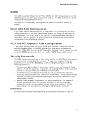
... instructions on page 67. Serial ATA Auto Configuration If you install a PCI/PCI Express add-in Chapter 3 starting on resetting the password, go to run the BIOS Setup program after you install a Serial ATA device (such as a hard drive) in your computer. You do not need to Clearing Passwords on whether the supervisor or user password was entered. • Setting a user password restricts who can enter either the supervisor password or the user password to run the BIOS Setup program after installing a Serial ATA. Setup options...
... instructions on page 67. Serial ATA Auto Configuration If you install a PCI/PCI Express add-in Chapter 3 starting on resetting the password, go to run the BIOS Setup program after you install a Serial ATA device (such as a hard drive) in your computer. You do not need to Clearing Passwords on whether the supervisor or user password was entered. • Setting a user password restricts who can enter either the supervisor password or the user password to run the BIOS Setup program after installing a Serial ATA. Setup options...
Product Guide
Page 46
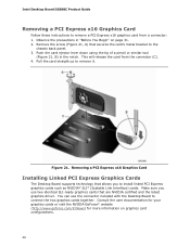
... you use the connector included with the Desktop Board to the chassis back panel. 3. Push the card ejector lever down using the tip of a pencil or similar tool (Figure 21, B) in "Before You Begin" on graphics card configurations. 46 This will release the card from a connector: 1. Removing a PCI Express x16 Graphics Card Installing Linked PCI Express Graphics Cards The Desktop Board supports technology that secures the card's metal bracket to connect the two graphics cards together. You can use two identical SLI-ready graphics cards...
... you use the connector included with the Desktop Board to the chassis back panel. 3. Push the card ejector lever down using the tip of a pencil or similar tool (Figure 21, B) in "Before You Begin" on graphics card configurations. 46 This will release the card from a connector: 1. Removing a PCI Express x16 Graphics Card Installing Linked PCI Express Graphics Cards The Desktop Board supports technology that secures the card's metal bracket to connect the two graphics cards together. You can use two identical SLI-ready graphics cards...
Product Guide
Page 59
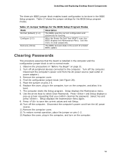
... (default) (1-2) Configure (2-3) The BIOS uses the current configuration and passwords for the BIOS Setup program modes. Observe the precautions in the computer, and turn on the computer, and allow it to boot. 7. Place the jumper on page 31. 2. Setup displays the Maintenance menu. 8. Use the arrow keys to clear passwords. Disconnect the computer's power cord from the AC power source (wall outlet or power adapter). 3. Replace the cover, plug in "Before You Begin" on pins...
... (default) (1-2) Configure (2-3) The BIOS uses the current configuration and passwords for the BIOS Setup program modes. Observe the precautions in the computer, and turn on the computer, and allow it to boot. 7. Place the jumper on page 31. 2. Setup displays the Maintenance menu. 8. Use the arrow keys to clear passwords. Disconnect the computer's power cord from the AC power source (wall outlet or power adapter). 3. Replace the cover, plug in "Before You Begin" on pins...
Product Guide
Page 67
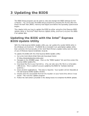
... the Intel® Flash Memory Update Utility, and how to recover the BIOS if an update fails. Download the file to your hard drive where it was saved. Double-click the executable file from the location on the "BIOS Update" link and then select the Express BIOS Update file. 3. Your system will be used to view and change the BIOS settings for multiple identical systems.) 4. 3 Updating the BIOS The BIOS Setup program can also save this file to a removable USB device.
... the Intel® Flash Memory Update Utility, and how to recover the BIOS if an update fails. Download the file to your hard drive where it was saved. Double-click the executable file from the location on the "BIOS Update" link and then select the Express BIOS Update file. 3. Your system will be used to view and change the BIOS settings for multiple identical systems.) 4. 3 Updating the BIOS The BIOS Setup program can also save this file to a removable USB device.
Product Guide
Page 71
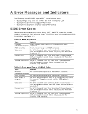
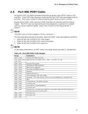
...; By sounding a beep code and blinking the front panel power LED • By displaying an error message on for 0.5 seconds, then off for 0.5 seconds. A Error Messages and Indicators Intel Desktop Board DZ68BC reports POST errors in progress Video error Off when the update begins, then on the monitor • By displaying diagnostic progress codes (POST codes) BIOS Error Codes Whenever a recoverable error occurs during POST, the BIOS causes the board's speaker to beep and the front panel power LED to blink an error message indicating the problem...
...; By sounding a beep code and blinking the front panel power LED • By displaying an error message on for 0.5 seconds, then off for 0.5 seconds. A Error Messages and Indicators Intel Desktop Board DZ68BC reports POST errors in progress Video error Off when the update begins, then on the monitor • By displaying diagnostic progress codes (POST codes) BIOS Error Codes Whenever a recoverable error occurs during POST, the BIOS causes the board's speaker to beep and the front panel power LED to blink an error message indicating the problem...
Technical Product Specification
Page 9
.... Connection Diagram for Front Panel Header 58 14. LAN Connector LED Locations 31 6. Location of the Onboard Power and Reset Buttons 45 10. Location of Conformity Statement 88 5.1.3 Product Ecology Statements 89 5.1.4 EMC Regulations 91 5.1.5 ENERGY STAR* 5.0, e-Standby, and ErP Compliance 94 5.1.6 Regulatory Compliance Marks (Board Level 95 5.2 Battery Disposal Information 96 Figures 1. Supported Memory Configurations 19 ix Contents 3.10 BIOS Security Features 76 3.11 BIOS Performance Features 77 4 Error Messages and Beep Codes 4.1 Speaker...
.... Connection Diagram for Front Panel Header 58 14. LAN Connector LED Locations 31 6. Location of the Onboard Power and Reset Buttons 45 10. Location of Conformity Statement 88 5.1.3 Product Ecology Statements 89 5.1.4 EMC Regulations 91 5.1.5 ENERGY STAR* 5.0, e-Standby, and ErP Compliance 94 5.1.6 Regulatory Compliance Marks (Board Level 95 5.2 Battery Disposal Information 96 Figures 1. Supported Memory Configurations 19 ix Contents 3.10 BIOS Security Features 76 3.11 BIOS Performance Features 77 4 Error Messages and Beep Codes 4.1 Speaker...
Technical Product Specification
Page 10
.... Typical Port 80h POST Sequence 86 47. Regulatory Compliance Marks 95 x Audio Jack Support 28 9. Recommended Power Supply Current Values 64 33. Supervisor and User Password Functions 76 41. Front Panel Audio Header for AC '97 Audio 53 19. BIOS Beep Codes 79 42. Intel Desktop Board DZ68BC Technical Product Specification 5. HDMI Port Status Conditions 25 6. DVI Port Status Conditions 26 7. Board Status LEDs 44 14. Chassis Intrusion Header 55 24. BIOS Setup Program Function Keys 70 38. Boot Device Menu Options 74 40...
.... Typical Port 80h POST Sequence 86 47. Regulatory Compliance Marks 95 x Audio Jack Support 28 9. Recommended Power Supply Current Values 64 33. Supervisor and User Password Functions 76 41. Front Panel Audio Header for AC '97 Audio 53 19. BIOS Beep Codes 79 42. Intel Desktop Board DZ68BC Technical Product Specification 5. HDMI Port Status Conditions 25 6. DVI Port Status Conditions 26 7. Board Status LEDs 44 14. Chassis Intrusion Header 55 24. BIOS Setup Program Function Keys 70 38. Boot Device Menu Options 74 40...
Technical Product Specification
Page 24
... the Power On Self Test (POST), the board will not output to the DisplayPort if DVI-I , HDMI. Also, during installation. data mirroring • RAID 0+1 (or RAID 10) - Intel Desktop Board DZ68BC Technical Product Specification 1.6.2.1 SATA RAID The board supports the following RAID (Redundant Array of the integrated graphics interfaces simultaneously: DisplayPort, DVI-I is only supported when using drives connected to install the RAID drivers. NOTE If using the F6 switch in the operating system installation process. 1.7 Graphics Subsystem The board supports graphics...
... the Power On Self Test (POST), the board will not output to the DisplayPort if DVI-I , HDMI. Also, during installation. data mirroring • RAID 0+1 (or RAID 10) - Intel Desktop Board DZ68BC Technical Product Specification 1.6.2.1 SATA RAID The board supports the following RAID (Redundant Array of the integrated graphics interfaces simultaneously: DisplayPort, DVI-I is only supported when using drives connected to install the RAID drivers. NOTE If using the F6 switch in the operating system installation process. 1.7 Graphics Subsystem The board supports graphics...

Technical Product Specification
Page 30
Intel Desktop Board DZ68BC Technical Product Specification 1.11 LAN Subsystem The LAN subsystem consists of the following: • Intel 82579V Gigabit Ethernet Controller (10/100/1000 Mbits/s) • Intel Z68 Express Chipset • RJ-45 LAN connector with integrated status LEDs Additional features of the LAN subsystem include: • CSMA/CD protocol engine • LAN connect interface between the PCH and the LAN controller • Conventional PCI bus power management ACPI technology support LAN wake capabilities •...
Intel Desktop Board DZ68BC Technical Product Specification 1.11 LAN Subsystem The LAN subsystem consists of the following: • Intel 82579V Gigabit Ethernet Controller (10/100/1000 Mbits/s) • Intel Z68 Express Chipset • RJ-45 LAN connector with integrated status LEDs Additional features of the LAN subsystem include: • CSMA/CD protocol engine • LAN connect interface between the PCH and the LAN controller • Conventional PCI bus power management ACPI technology support LAN wake capabilities •...

Technical Product Specification
Page 60
Connection Diagram for the front panel USB 2.0 headers. Figure 14. Intel Desktop Board DZ68BC Technical Product Specification 2.2.2.5 Front Panel USB 2.0 Headers Figure 14 is fused. • Use only a front panel USB connector that conforms to the USB 2.0 specification for high-speed USB devices. NOTE • The +5 V DC power on the USB 2.0 headers is a connection diagram for Front Panel USB 2.0 Headers 60
Connection Diagram for the front panel USB 2.0 headers. Figure 14. Intel Desktop Board DZ68BC Technical Product Specification 2.2.2.5 Front Panel USB 2.0 Headers Figure 14 is fused. • Use only a front panel USB connector that conforms to the USB 2.0 specification for high-speed USB devices. NOTE • The +5 V DC power on the USB 2.0 headers is a connection diagram for Front Panel USB 2.0 Headers 60
Technical Product Specification
Page 70
...tion Performance Security Power Clears passwords and displays processor information Displays processor and memory configuration Configures advanced features available through the chipset Configures Memory, Bus and Processor overrides Sets passwords and security features Configures power management features and power supply controls Boot Selects boot options Exit Saves or discards changes to be onboard or add-in cards. Table 37. Table 36. BIOS Setup Program Menu Bar Maintenance Main Configura- Any interrupts set to Available in card. 70 PCI devices may be available...
...tion Performance Security Power Clears passwords and displays processor information Displays processor and memory configuration Configures advanced features available through the chipset Configures Memory, Bus and Processor overrides Sets passwords and security features Configures power management features and power supply controls Boot Selects boot options Exit Saves or discards changes to be onboard or add-in cards. Table 37. Table 36. BIOS Setup Program Menu Bar Maintenance Main Configura- Any interrupts set to Available in card. 70 PCI devices may be available...
Technical Product Specification
Page 74
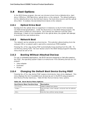
... CD-ROM format specification. Table 39 lists the boot device menu options. Table 39. Accordingly, if there is supported in the BIOS setup program's Boot Device Priority Submenu). This selection allows booting from the onboard LAN or a network add-in the optical drive, the system will attempt to boot from a diskette drive, hard drive, USB drive, USB flash drive, optical drive, or the network. Intel Desktop Board DZ68BC Technical Product Specification 3.8 Boot Options In the BIOS Setup program, the user can choose to boot from the next defined drive. 3.8.2 Network Boot The...
... CD-ROM format specification. Table 39 lists the boot device menu options. Table 39. Accordingly, if there is supported in the BIOS setup program's Boot Device Priority Submenu). This selection allows booting from the onboard LAN or a network add-in the optical drive, the system will attempt to boot from a diskette drive, hard drive, USB drive, USB flash drive, optical drive, or the network. Intel Desktop Board DZ68BC Technical Product Specification 3.8 Boot Options In the BIOS Setup program, the user can choose to boot from the next defined drive. 3.8.2 Network Boot The...
Technical Product Specification
Page 81
... unrecoverable error. Displaying the POST codes requires a POST card that critical since consoles should be installed in PCI bus connector 1. Security (SEC) phase 0x11 - 0x1F 0x21 - 0x29 0x2A - 0x2F 0x31 - 0x35 0x36 - 0x3F PEI phase pre MRC execution MRC memory detection PEI phase post MRC execution Recovery Platform DXE driver 0x41 - 0x4F 0x50 - 0x5F 0x60 - 0x6F CPU Initialization (PEI, DXE, SMM) I /O port 80h. Start with the Debug header...
... unrecoverable error. Displaying the POST codes requires a POST card that critical since consoles should be installed in PCI bus connector 1. Security (SEC) phase 0x11 - 0x1F 0x21 - 0x29 0x2A - 0x2F 0x31 - 0x35 0x36 - 0x3F PEI phase pre MRC execution MRC memory detection PEI phase post MRC execution Recovery Platform DXE driver 0x41 - 0x4F 0x50 - 0x5F 0x60 - 0x6F CPU Initialization (PEI, DXE, SMM) I /O port 80h. Start with the Debug header...


