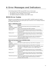
Intel Desktop Board DX79SI Technical Product Specification
Page 5
... This Document Contains Chapter 1 2 3 4 5 Description A description of the hardware used on the Intel Desktop Board DX79SI A map of the resources of the Intel Desktop Board The features supported by the BIOS Setup program A description of the BIOS error messages, beep codes, and POST codes Regulatory compliance and battery disposal information Typographical Conventions This section contains information...
Intel Desktop Board DX79SI Technical Product Specification
Page 8
Intel Desktop Board DX79SI Technical Product Specification 2 Technical Reference 2.1 Memory Resources 43 2.1.1 Addressable Memory 43 2.1.2 Memory Map 45 2.2 Connectors and Headers 45 2.2.1 Back Panel Connectors 46 2.2.2 Component-side Connectors ... POST 72 3.9 Adjusting Boot Speed 73 3.9.1 Peripheral Selection and Configuration 73 3.9.2 BIOS Boot Optimizations 73 3.10 BIOS Security Features 74 3.11 BIOS Performance Features 75 4 Error Messages and Beep Codes 4.1 Speaker 77 4.2 BIOS Beep Codes 77 4.3 Front-panel Power LED Blink Codes 78 4.4 BIOS Error Messages 78 4.5 Port 80h POST...
Intel Desktop Board DX79SI Technical Product Specification
Page 10
Chassis Intrusion Header 52 20. Main Power Connector 54 23. States for Components 64 30. BIOS Setup Configuration Jumper Settings 59 27. BIOS Error Messages 78 39. Regulatory Compliance Marks 93 x S/PDIF Header 51 17. USB 2.0 Headers 51 18. USB 3.0 Connector 52 19. Thermal ...for a One-Color Power LED 56 25. Port 80h POST Code Ranges 79 40. Port 80h POST Codes 80 41. Typical Port 80h POST Sequence 84 42. Recommended Power Supply Current Values 61 28. Intel Desktop Board DX79SI Technical Product Specification 14. Processor Core Power Connector 54 22. ...
Intel Desktop Board DX79SI Technical Product Specification
Page 77
... (off ), entire pattern repeats (beeps and pause) once and the BIOS will continue to beep an error message describing the problem (see Table 37). 4 Error Messages and Beep Codes 4.1 Speaker The board-mounted speaker provides audible error code (beep code) information during POST, the BIOS causes the board's speaker to boot. For information about The location...
Intel Desktop Board DX79SI Technical Product Specification
Page 78
...boot. If no VGA option ROM is found. 4.4 BIOS Error Messages Table 39 lists the error messages and provides a brief description of 16 blinks. Intel Desktop Board DX79SI Technical Product Specification 4.3 Front-panel Power LED Blink Codes Whenever a recoverable error occurs during POST, the BIOS causes the board's front ... Off when the update begins, then on , .25 seconds off . Run Setup to blink an error message describing the problem (see Table 38). Front-panel Power LED Blink Codes Type Pattern F2 Setup/F10 Boot Menu None Prompt BIOS update in a total of each ) three ...
Intel Desktop Board DX79SI Technical Product Specification
Page 79
... the contents on a medium such as a seven-segment display. Port 80h POST Code Ranges Range Subsystem 0x00 - 0x05 Entering SX states S0 to I /O Buses: PCI, USB, ATA etc. 0x5F is an unrecoverable error. This code is left at this point. 0xC0 - 0xCF For future use 0xD0 - 0xDF ... 80h POST sequence NOTE In the tables listed above, all POST codes and range values are listed in hexadecimal. S2, 0x30 - Table 40. Error Messages and Beep Codes 4.5 Port 80h POST Codes During the POST, the BIOS generates diagnostic progress codes (POST codes) to S5. 0x10, 0x20, 0x30, 0x40, 0x50 0x08 -...
Intel Desktop Board DX79SI Technical Product Specification
Page 81
Error Messages and Beep Codes Table 41. Port 80h POST Codes (continued) Port 80 Code Progress Code Enumeration PEIMs/Recovery 0x31 Crisis Recovery has initiated 0x33 Loading recovery capsule 0x34 Start recovery capsule/ valid capsule is found CPU Initialization CPU PEI Phase ...
Product Guide for Intel Desktop Board DX79SI
Page 3
...Intel® Desktop Board DX79SI. Document Organization The chapters in homes, offices, schools, computer rooms, and similar locations. The suitability of this manual: CAUTION Cautions warn the user about board layout, component installation, BIOS update, and regulatory requirements for technically qualified personnel. Use Only for Intended Applications All Intel... without further evaluation by Intel. Intended Audience The Product Guide is not intended for RAID A Error Messages and Indicators: information about BIOS error messages and beep codes B Regulatory Compliance: describes...
Product Guide for Intel Desktop Board DX79SI
Page 7
...Module 30 9. Unlatch the Socket Levers 37 13. Open the Load Plate 38 14. Close the Load Plate 40 16. Intel Desktop Board DX79SI Mounting Screw Hole Locations 36 12. Location of the Back to the Processor Fan Header 41 17. Location of Communications Compliance Statement... Creating Your RAID Set 71 Loading the Intel RST RAID Drivers and Software (Required for Microsoft Windows XP Installation 72 Setting Up a "RAID Ready" System 72 A Error Messages and Indicators BIOS Error Codes 73 BIOS Error Messages 74 Port 80h POST Codes 75 B Regulatory Compliance Safety Standards 79 ...
Product Guide for Intel Desktop Board DX79SI
Page 8
...the BIOS Setup Program Modes 58 17. Front-panel Power LED Blink Codes 73 19. Safety Standards 79 22. Intel Desktop Board DX79SI Product Guide 19. USB 3.0 Connector 51 11. BIOS Beep Codes 73 18. BIOS Error Messages 74 20. Regulatory Compliance Marks 88 viii Internal Headers 49 ...23. Location of the Chassis Fan Headers 55 25. POST Code LED Display 75 31....
Product Guide for Intel Desktop Board DX79SI
Page 29
The speaker provides audible error code (beep code) information during the Power-On Self-Test (POST). Status LEDs LED Item/Callout LED in Figure 7 Color HD Activity H Blue CPU Hot I Red VR Hot J Red CPU Error F Red Power Fault M Red Description This LED blinks to the board...off and disconnected from AC power. Table 5. Desktop Board Features Status LEDs The LEDs in Table 5 indicate various board activities and error conditions on the Desktop Board. This LED indicates an elevated temperature in CMOS RAM and the clock current when the computer is ...
Product Guide for Intel Desktop Board DX79SI
Page 73
... is powered off . The pattern repeats until the system is complete. A Error Messages and Indicators Intel Desktop Board DX79SI reports POST errors in progress Off when the update begins, then on the monitor • By displaying diagnostic progress codes (POST codes) BIOS Error Codes Whenever a recoverable error occurs during POST, the BIOS causes the board's speaker to beep and...
Product Guide for Intel Desktop Board DX79SI
Page 75
Error Messages and Indicators Port 80h POST Codes During the POST, the BIOS generates diagnostic progress codes (POST codes) to I/O port 80h. If the POST fails, execution stops and the last POST code generated is useful for determining the point where an error occurred during the POST. Figure 30. POST Code LED Display 75 This code is left at port 80h and displayed on the Desktop Board's seven-segment LED display shown in Figure 30.
Product Guide for Intel Desktop Board DX79SI
Page 77
Port 80h POST Codes (continued) 31, 33, 34 PEIMs/Recovery Recovery has initiate, load, valid 41-43 44-46 47-4C 4D-4F CPU Initialization (...52 58, 59 5A, 5B 5F I/O Buses PCI enumeration, allocation, hot plug Resetting USB bus Resetting SATA bus and all devices Unrecoverable error, start with PIC 60-6F E4 E7 E8 E9 EB Boot Device Selection (BDS) BDS driver entry Entered DXE phase Waiting for user ...initializing fixed media Runtime Phase/EFI Operating System Boot F8 EFI boot service ExitBootServices F9 EFI runtime service SetVirtualAddressMap 77 Error Messages and Indicators Table 20.