

Intel Desktop Board DX79SI Technical Product Specification
Page 10
...Keys 68 33. BIOS Beep Codes 77 37. Port 80h POST Code Ranges 79 40. Typical Port 80h POST Sequence 84 42. S/PDIF Header 51 17. USB 3.0 Connector 52 19. Processor, Front and Rear Chassis, and Auxiliary (4-Pin) Fan Headers ..... 52 21. Safety Standards 85 43. Intel Desktop Board DX79SI... Technical Product Specification 14. States for BIOS Recovery 71 34. SATA Connectors 51 16. Chassis Intrusion Header 52 20. Acceptable Drives/Media Types for ...
...Keys 68 33. BIOS Beep Codes 77 37. Port 80h POST Code Ranges 79 40. Typical Port 80h POST Sequence 84 42. S/PDIF Header 51 17. USB 3.0 Connector 52 19. Processor, Front and Rear Chassis, and Auxiliary (4-Pin) Fan Headers ..... 52 21. Safety Standards 85 43. Intel Desktop Board DX79SI... Technical Product Specification 14. States for BIOS Recovery 71 34. SATA Connectors 51 16. Chassis Intrusion Header 52 20. Acceptable Drives/Media Types for ...

Intel Desktop Board DX79SI Technical Product Specification
Page 50
... for stereo microphone support 4 PRESENCE# 5 FP_OUT_R 6 AUD_GND Active low signal that signals BIOS that an Intel HD Audio dongle is connected to the analog header. PRESENCE#=0 when an Intel HD Audio dongle is connected. Front Panel Audio Header for AC '97 Audio Pin Signal...resistor network 8 KEY No pin 9 PORT_2L Analog Port 2 - PRESENCE#=0 when an Intel HD Audio dongle is connected 5 PORT_2R Analog Port 2 - Right channel audio signal to front panel (headphone drive capable) Ground used by analog audio circuits 50 Intel Desktop Board DX79SI Technical Product ...
... for stereo microphone support 4 PRESENCE# 5 FP_OUT_R 6 AUD_GND Active low signal that signals BIOS that an Intel HD Audio dongle is connected to the analog header. PRESENCE#=0 when an Intel HD Audio dongle is connected. Front Panel Audio Header for AC '97 Audio Pin Signal...resistor network 8 KEY No pin 9 PORT_2L Analog Port 2 - PRESENCE#=0 when an Intel HD Audio dongle is connected 5 PORT_2R Analog Port 2 - Right channel audio signal to front panel (headphone drive capable) Ground used by analog audio circuits 50 Intel Desktop Board DX79SI Technical Product ...

Intel Desktop Board DX79SI Technical Product Specification
Page 67
...identified as SIX7910J.86A. The menu bar is accessed by pressing the key after the Power-On Self-Test (POST) memory test begins and before the operating system boot begins. The SPI Flash contains the BIOS Setup program, POST, the PCI auto-configuration utility, LAN EEPROM information...configure mode and the computer is powered-up, the BIOS compares the CPU version and the microcode version in configure mode. 67 The BIOS displays a message during POST identifying the type of BIOS Features 3.1 Introduction The board uses an Intel BIOS that is in the Serial Peripheral Interface Flash Memory...
...identified as SIX7910J.86A. The menu bar is accessed by pressing the key after the Power-On Self-Test (POST) memory test begins and before the operating system boot begins. The SPI Flash contains the BIOS Setup program, POST, the PCI auto-configuration utility, LAN EEPROM information...configure mode and the computer is powered-up, the BIOS compares the CPU version and the microcode version in configure mode. 67 The BIOS displays a message during POST identifying the type of BIOS Features 3.1 Introduction The board uses an Intel BIOS that is in the Serial Peripheral Interface Flash Memory...

Intel Desktop Board DX79SI Technical Product Specification
Page 68
... devices. BIOS Setup Program Function Keys BIOS Setup Program Function Key Description or Selects a different menu screen (Moves the cursor left or right) or Selects an item (Moves the cursor up or down) Selects a field (Not implemented) Executes command or selects the submenu Load the default configuration values for menu screens. Intel Desktop Board DX79SI Technical...
... devices. BIOS Setup Program Function Keys BIOS Setup Program Function Key Description or Selects a different menu screen (Moves the cursor left or right) or Selects an item (Moves the cursor up or down) Selects a field (Not implemented) Executes command or selects the submenu Load the default configuration values for menu screens. Intel Desktop Board DX79SI Technical...

Intel Desktop Board DX79SI Technical Product Specification
Page 72
... a boot device menu to Full. 3.8.3 Booting Without Attached Devices For use this key during POST automatically forces booting from the selected device Exits the menu without saving changes 72 Intel Desktop Board DX79SI Technical Product Specification 3.8 Boot Options In the BIOS Setup program, the user can be the first boot device, the hard drive...
... a boot device menu to Full. 3.8.3 Booting Without Attached Devices For use this key during POST automatically forces booting from the selected device Exits the menu without saving changes 72 Intel Desktop Board DX79SI Technical Product Specification 3.8 Boot Options In the BIOS Setup program, the user can be the first boot device, the hard drive...
Intel Desktop Board DX79SI Technical Product Specification
Page 74
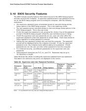
... supervisor password is set for the BIOS Setup program and for booting the computer, with the following restrictions: • The supervisor password gives unrestricted access to access Setup. The password prompt will be set , pressing the key at the password prompt of options Supervisor...the screen. Password to view and change Setup options in the BIOS Setup program. Intel Desktop Board DX79SI Technical Product Specification 3.10 BIOS Security Features The BIOS includes security features that restrict access to the BIOS Setup program and who can boot the computer. Table 36....
... supervisor password is set for the BIOS Setup program and for booting the computer, with the following restrictions: • The supervisor password gives unrestricted access to access Setup. The password prompt will be set , pressing the key at the password prompt of options Supervisor...the screen. Password to view and change Setup options in the BIOS Setup program. Intel Desktop Board DX79SI Technical Product Specification 3.10 BIOS Security Features The BIOS includes security features that restrict access to the BIOS Setup program and who can boot the computer. Table 36....
Product Guide for Intel Desktop Board DX79SI
Page 6
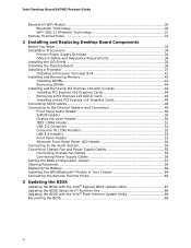
Intel Desktop Board DX79SI Product Guide Bluetooth*/WiFi Module 30 Bluetooth Technology 30 WiFi (802....Fan and Power Supply Cables 55 Connecting Chassis Fan Cables 55 Connecting Power Supply Cables 56 Setting the BIOS Configuration Jumper 57 Clearing Passwords 58 Replacing the Battery 59 Installing the WiFi/Bluetooth* Module in Your... the Remote Thermal Probe 65 3 Updating the BIOS Updating the BIOS with the Intel® Express BIOS Update Utility 67 Updating the BIOS Using the F7 Function Key 68 Updating the BIOS with the Intel® Flash Memory Update Utility 68 Recovering the...
Intel Desktop Board DX79SI Product Guide Bluetooth*/WiFi Module 30 Bluetooth Technology 30 WiFi (802....Fan and Power Supply Cables 55 Connecting Chassis Fan Cables 55 Connecting Power Supply Cables 56 Setting the BIOS Configuration Jumper 57 Clearing Passwords 58 Replacing the Battery 59 Installing the WiFi/Bluetooth* Module in Your... the Remote Thermal Probe 65 3 Updating the BIOS Updating the BIOS with the Intel® Express BIOS Update Utility 67 Updating the BIOS Using the F7 Function Key 68 Updating the BIOS with the Intel® Flash Memory Update Utility 68 Recovering the...
Product Guide for Intel Desktop Board DX79SI
Page 22
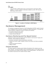
...switch on the chassis that detects if the chassis cover has been removed. Intel Desktop Board DX79SI Product Guide NOTE Using the Back to BIOS button does not set the board to the factory defaults, use the key once BIOS setup mode is active. Figure 4. See Figure 22 for Management (WfM...) specification. Location of the Back to BIOS Button Hardware Management The hardware management features of Intel Desktop Board DX79SI enable the board to be compatible with the...
...switch on the chassis that detects if the chassis cover has been removed. Intel Desktop Board DX79SI Product Guide NOTE Using the Back to BIOS button does not set the board to the factory defaults, use the key once BIOS setup mode is active. Figure 4. See Figure 22 for Management (WfM...) specification. Location of the Back to BIOS Button Hardware Management The hardware management features of Intel Desktop Board DX79SI enable the board to be compatible with the...
Product Guide for Intel Desktop Board DX79SI
Page 52
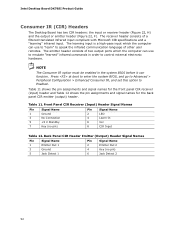
... output ports which the computer can use to emulate "learned" infrared commands in the system BIOS before it can use to "learn" to Enabled. Press at boot to enter the system BIOS, and go to Advanced > Peripheral Configuration > Enhanced Consumer IR, and set this option ... Signal Name 1 Emitter Out 1 3 Ground 5 Jack Detect 1 Pin Signal Name 2 Emitter Out 2 4 Key (no pin) Pin Signal Name 2 LED 4 Learn-In 6 Vcc 8 CIR Input Table 12. Intel Desktop Board DX79SI Product Guide Consumer IR (CIR) Headers The Desktop Board has two CIR headers: the input or receiver header...
... output ports which the computer can use to emulate "learned" infrared commands in the system BIOS before it can use to "learn" to Enabled. Press at boot to enter the system BIOS, and go to Advanced > Peripheral Configuration > Enhanced Consumer IR, and set this option ... Signal Name 1 Emitter Out 1 3 Ground 5 Jack Detect 1 Pin Signal Name 2 Emitter Out 2 4 Key (no pin) Pin Signal Name 2 LED 4 Learn-In 6 Vcc 8 CIR Input Table 12. Intel Desktop Board DX79SI Product Guide Consumer IR (CIR) Headers The Desktop Board has two CIR headers: the input or receiver header...

Product Guide for Intel Desktop Board DX79SI
Page 58
...mode. 1. Disconnect the computer's power cord from the AC power source (wall outlet or power adapter). 3. Intel Desktop Board DX79SI Product Guide Table 16. Use the arrow keys to clear passwords. To restore normal operation, place the jumper on page 33. 2. After the Power-On...9. Observe the precautions in the computer, turn on the computer. 58 Jumper Settings for the BIOS Setup Program Modes Mode Normal (default) (1-2) Configure (2-3) Recovery (None) Description The BIOS uses the current configuration and passwords for booting. Select Yes and press . Setup displays the ...
...mode. 1. Disconnect the computer's power cord from the AC power source (wall outlet or power adapter). 3. Intel Desktop Board DX79SI Product Guide Table 16. Use the arrow keys to clear passwords. To restore normal operation, place the jumper on page 33. 2. After the Power-On...9. Observe the precautions in the computer, turn on the computer. 58 Jumper Settings for the BIOS Setup Program Modes Mode Normal (default) (1-2) Configure (2-3) Recovery (None) Description The BIOS uses the current configuration and passwords for booting. Select Yes and press . Setup displays the ...

Product Guide for Intel Desktop Board DX79SI
Page 67
.... (You can be rebooted at http://downloadcenter.intel.com/ 2. Close all other applications. This runs the update program. 6. This chapter tells you how to update the BIOS by pressing the F2 key after the Power-On Self-Test (POST) memory...BIOS with the Intel® Express BIOS Update Utility With the Intel Express BIOS Update utility you are updating the BIOS for the computer. This step is included in the dialog boxes to complete the BIOS update. 67 3 Updating the BIOS The BIOS Setup program can also save this file to a removable USB device. Download the file to the DX79SI...
.... (You can be rebooted at http://downloadcenter.intel.com/ 2. Close all other applications. This runs the update program. 6. This chapter tells you how to update the BIOS by pressing the F2 key after the Power-On Self-Test (POST) memory...BIOS with the Intel® Express BIOS Update Utility With the Intel Express BIOS Update utility you are updating the BIOS for the computer. This step is included in the dialog boxes to complete the BIOS update. 67 3 Updating the BIOS The BIOS Setup program can also save this file to a removable USB device. Download the file to the DX79SI...

Product Guide for Intel Desktop Board DX79SI
Page 68
... the Intel Desktop Board DX79SI page on the "BIOS Update" link and then select the Iflash BIOS Update file. 68 Press the F10 key to save the Recovery BIOS (.BIO) file to a temporary directory. 2. The Intel Flash Memory BIOS update file is displayed, press the F7 key to enter the BIOS Flash Update tool. 7. On the DX79SI page, click on the Intel World...
... the Intel Desktop Board DX79SI page on the "BIOS Update" link and then select the Iflash BIOS Update file. 68 Press the F10 key to save the Recovery BIOS (.BIO) file to a temporary directory. 2. The Intel Flash Memory BIOS update file is displayed, press the F7 key to enter the BIOS Flash Update tool. 7. On the DX79SI page, click on the Intel World...

Product Guide for Intel Desktop Board DX79SI
Page 69
... in the root directory will interrupt the BIOS update; Recovering the BIOS It is complete. On the Intel Desktop Board DX79SI page, click on the Intel World Wide Web site Download Center at http://downloadcenter.intel.com. Configure the BIOS or use the F10 key option during POST to boot to BIOS size and recovery requirements, a CD-R with the...
... in the root directory will interrupt the BIOS update; Recovering the BIOS It is complete. On the Intel Desktop Board DX79SI page, click on the Intel World Wide Web site Download Center at http://downloadcenter.intel.com. Configure the BIOS or use the F10 key option during POST to boot to BIOS size and recovery requirements, a CD-R with the...
Product Guide for Intel Desktop Board DX79SI
Page 71
...if three or four SATA drives are installed respectively). Enter a volume name (using English alphanumeric ASCII characters) and press . 3. Use the arrow keys to select RAID 0 or RAID 1 (if only two SATA drives are more SATA hard drives to the black SATA connectors. 2. Enter the ...Test (POST) memory tests begin. 3. Go to : • Configure the BIOS for RAID • Create a RAID Set • Load the Intel RST RAID Drivers and Software (required for RAID Using Intel® Rapid Storage Technology NOTE Intel RST requires a Microsoft Windows 7, Microsoft Windows Vista, or Microsoft Windows XP ...
...if three or four SATA drives are installed respectively). Enter a volume name (using English alphanumeric ASCII characters) and press . 3. Use the arrow keys to select RAID 0 or RAID 1 (if only two SATA drives are more SATA hard drives to the black SATA connectors. 2. Enter the ...Test (POST) memory tests begin. 3. Go to : • Configure the BIOS for RAID • Create a RAID Set • Load the Intel RST RAID Drivers and Software (required for RAID Using Intel® Rapid Storage Technology NOTE Intel RST requires a Microsoft Windows 7, Microsoft Windows Vista, or Microsoft Windows XP ...


