
Intel Desktop Board DX79SI Technical Product Specification
Page 29
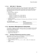
...; IEEE 802.11N supports up to 300 meters • Supports the following : • Processor and system ambient temperature monitoring • Chassis fan speed monitoring • Power monitoring of WiFi enabled networks, access points and allows peer to be compatible with a variety of +12 V, +5 V, +3.3 V, V_SM1, V_SM2, 3.3V_Standby and +...about Obtaining WiFi information and drivers Refer to http://msdn.microsoft.com/enus/library/aa362932(VS.85).aspx http://downloadcenter.intel.com 1.12 Hardware Management Subsystem The hardware management features enable the board to peer connections.
...; IEEE 802.11N supports up to 300 meters • Supports the following : • Processor and system ambient temperature monitoring • Chassis fan speed monitoring • Power monitoring of WiFi enabled networks, access points and allows peer to be compatible with a variety of +12 V, +5 V, +3.3 V, V_SM1, V_SM2, 3.3V_Standby and +...about Obtaining WiFi information and drivers Refer to http://msdn.microsoft.com/enus/library/aa362932(VS.85).aspx http://downloadcenter.intel.com 1.12 Hardware Management Subsystem The hardware management features enable the board to peer connections.
Intel Desktop Board DX79SI Technical Product Specification
Page 54
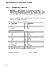
a 2 x 12 connector. Failure to the processor voltage regulator and must always be unconnected. Intel Desktop Board DX79SI Technical Product Specification 2.2.2.3 Power Supply Connectors The board has the following power supply connectors: • Main power - This connector is compatible with either 2 x 10 or 2 x 12 main power cables. Main Power Connector Pin Signal Name 1 +3.3 V 2 +3.3 V Pin Signal Name...
a 2 x 12 connector. Failure to the processor voltage regulator and must always be unconnected. Intel Desktop Board DX79SI Technical Product Specification 2.2.2.3 Power Supply Connectors The board has the following power supply connectors: • Main power - This connector is compatible with either 2 x 10 or 2 x 12 main power cables. Main Power Connector Pin Signal Name 1 +3.3 V 2 +3.3 V Pin Signal Name...
Product Guide for Intel Desktop Board DX79SI
Page 7
... Load Plate 40 16. Intel Desktop Board DX79SI Mounting Screw Hole Locations 36 12. Unlatch the Socket Levers 37 13. Location of Communications Compliance Statement 86 Japan VCCI Statement 86 Korea Class B Statement 87 Ensure Electromagnetic Compatibility (EMC) Compliance 87 Product Certifications 88 Board-Level Certifications 88 Chassis- Install the Processor 39 15. Contents...
... Load Plate 40 16. Intel Desktop Board DX79SI Mounting Screw Hole Locations 36 12. Unlatch the Socket Levers 37 13. Location of Communications Compliance Statement 86 Japan VCCI Statement 86 Korea Class B Statement 87 Ensure Electromagnetic Compatibility (EMC) Compliance 87 Product Certifications 88 Board-Level Certifications 88 Chassis- Install the Processor 39 15. Contents...

Product Guide for Intel Desktop Board DX79SI
Page 17
...drivers that fully support USB 3.0 transfer rates. USB 2.0 There are backward compatible with two USB 3.0 ports (blue) on configuring your system for more information about the Intel X79 Express Chipset: http://developer.intel.com/products/chipsets/index.htm USB Support The Desktop Board supports USB 3.0 ...following RAID (Redundant Array of the Intel X79 Platform Controller Hub (PCH) provides interfaces to three onboard headers (black)). USB 3.0 ports are 14 USB 2.0 ports (six ports routed to back panel connectors (black) and eight ports routed to the processor and the USB, SATA, LAN, ...
...drivers that fully support USB 3.0 transfer rates. USB 2.0 There are backward compatible with two USB 3.0 ports (blue) on configuring your system for more information about the Intel X79 Express Chipset: http://developer.intel.com/products/chipsets/index.htm USB Support The Desktop Board supports USB 3.0 ...following RAID (Redundant Array of the Intel X79 Platform Controller Hub (PCH) provides interfaces to three onboard headers (black)). USB 3.0 ports are 14 USB 2.0 ports (six ports routed to back panel connectors (black) and eight ports routed to the processor and the USB, SATA, LAN, ...
Product Guide for Intel Desktop Board DX79SI
Page 22
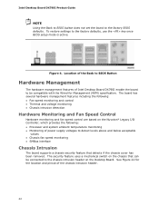
... that detects if the chassis cover has been removed. The board has several hardware management features including the following : • Processor and system ambient temperature monitoring • Monitoring of power supply voltages to the factory BIOS defaults. To restore settings to be...Intel Desktop Board DX79SI Product Guide NOTE Using the Back to BIOS button does not set the board to detect levels above and below acceptable values • Chassis fan speed monitoring • SMBus interface Chassis Intrusion The board supports a chassis security feature that can be compatible...
... that detects if the chassis cover has been removed. The board has several hardware management features including the following : • Processor and system ambient temperature monitoring • Monitoring of power supply voltages to the factory BIOS defaults. To restore settings to be...Intel Desktop Board DX79SI Product Guide NOTE Using the Back to BIOS button does not set the board to detect levels above and below acceptable values • Chassis fan speed monitoring • SMBus interface Chassis Intrusion The board supports a chassis security feature that can be compatible...

Product Guide for Intel Desktop Board DX79SI
Page 56
Connect the 12 V processor core voltage power supply cable to the board or the system may not function properly. Connecting Power Supply Cables 1. Intel Desktop Board DX79SI Product Guide Connecting Power Supply Cables Figure 25 shows the location of the power connectors. CAUTION Failure to use an appropriate power supply and/or ... 25. Connect the main power supply cable to the 2 x 12 pin connector (Figure 25, B). 56 The 2 x 12 pin main power connector (Figure 25, B) is backwards compatible with ATX12V power supplies with 2 x 10 connectors.
Connect the 12 V processor core voltage power supply cable to the board or the system may not function properly. Connecting Power Supply Cables 1. Intel Desktop Board DX79SI Product Guide Connecting Power Supply Cables Figure 25 shows the location of the power connectors. CAUTION Failure to use an appropriate power supply and/or ... 25. Connect the main power supply cable to the 2 x 12 pin connector (Figure 25, B). 56 The 2 x 12 pin main power connector (Figure 25, B) is backwards compatible with ATX12V power supplies with 2 x 10 connectors.


