Product Guide
Page 6
Intel Desktop Board DQ35JO Product Guide 2 Installing and Replacing Desktop Board Components Before You Begin 31 Installation Precautions 32 Prevent Power Supply Overload 32 Observe Safety and Regulatory Requirements 32 Installing the I/O Shield 33 Installing and Removing the Desktop Board 34 Installing and Removing a Processor 35 Installing a...Connecting to the HD Audio Link Header 51 Connecting to the IEEE 1394a Header 51 Installing a Front Panel Audio Solution for Intel® High Definition Audio 51 Connecting to the Serial Port Header 52 Connecting to the Chassis Intrusion Header...
Intel Desktop Board DQ35JO Product Guide 2 Installing and Replacing Desktop Board Components Before You Begin 31 Installation Precautions 32 Prevent Power Supply Overload 32 Observe Safety and Regulatory Requirements 32 Installing the I/O Shield 33 Installing and Removing the Desktop Board 34 Installing and Removing a Processor 35 Installing a...Connecting to the HD Audio Link Header 51 Connecting to the IEEE 1394a Header 51 Installing a Front Panel Audio Solution for Intel® High Definition Audio 51 Connecting to the Serial Port Header 52 Connecting to the Chassis Intrusion Header...

Product Guide
Page 8
... Header Names 51 8. Beep Codes 75 16. Product Certification Markings 85 viii Intel Desktop Board DQ35JO Product Guide 21. Safety Standards 77 18. Front Panel Intel High Definition Audio Header Signal Names 51 9. BIOS Error Messages 75 17. Back Panel Audio Connectors 54 26. Intel AMT Status Indicator 20 6. Connecting the External Serial ATA Adapter Bracket 49 24...
... Header Names 51 8. Beep Codes 75 16. Product Certification Markings 85 viii Intel Desktop Board DQ35JO Product Guide 21. Safety Standards 77 18. Front Panel Intel High Definition Audio Header Signal Names 51 9. BIOS Error Messages 75 17. Back Panel Audio Connectors 54 26. Intel AMT Status Indicator 20 6. Connecting the External Serial ATA Adapter Bracket 49 24...
Product Guide
Page 9
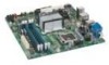
...100 support for two devices continued 9 1 Desktop Board Features This chapter briefly describes the features of : • Intel® Q35 Express Chipset Graphics and Memory Controller Hub (GMCH) • Intel® 82801IDO I/O Controller Hub (ICH9DO) • Intel® Graphics Media Accelerator 3100 graphics controller &#...back panel ― Six ports routed to three USB headers • Up to two IEEE 1394a ports ― One port routed to the back panel ― One port routed to 8 GB of system memory Intel® Q35 Express Chipset consisting of Intel® Desktop Board DQ35JO. ...
...100 support for two devices continued 9 1 Desktop Board Features This chapter briefly describes the features of : • Intel® Q35 Express Chipset Graphics and Memory Controller Hub (GMCH) • Intel® 82801IDO I/O Controller Hub (ICH9DO) • Intel® Graphics Media Accelerator 3100 graphics controller &#...back panel ― Six ports routed to three USB headers • Up to two IEEE 1394a ports ― One port routed to the back panel ― One port routed to 8 GB of system memory Intel® Q35 Express Chipset consisting of Intel® Desktop Board DQ35JO. ...
Product Guide
Page 10
... • Wake on USB, PCI Express, LAN, and front panel • ENERGY STAR* capable Hardware Management Intel® Active Management Technology (Intel® AMT) Hardware monitor with: • Intel® Quiet System Technology fan speed control • Three fan ... Intel® AMT Specification 3.0 provides IT organizations tamperresistant and persistent management capabilities Related Links: For more information about Desktop Board DQ35JO, including the Technical Product Specification (TPS), BIOS updates, and device drivers, go to: http://support.intel.com/support/motherboards/desktop/...
... • Wake on USB, PCI Express, LAN, and front panel • ENERGY STAR* capable Hardware Management Intel® Active Management Technology (Intel® AMT) Hardware monitor with: • Intel® Quiet System Technology fan speed control • Three fan ... Intel® AMT Specification 3.0 provides IT organizations tamperresistant and persistent management capabilities Related Links: For more information about Desktop Board DQ35JO, including the Technical Product Specification (TPS), BIOS updates, and device drivers, go to: http://support.intel.com/support/motherboards/desktop/...
Product Guide
Page 17
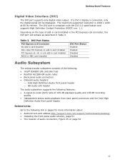
... to the following link or pages for more information about: • Audio drivers and utilities http://support.intel.com/support/motherboards/desktop/ • Installing the front panel audio solution, page 51 • The location of audio connectors, Figure 25 on the type of add...consists of the following: • Intel® ICH9DO I display is connected, only the digital signal will be displayed. The maximum supported resolution is compliant with the DVI 1.0 specification and supports High Definition Content Protection (HDCP) ver. 1.1. Desktop Board Features Digital Video Interface (DVI)...
... to the following link or pages for more information about: • Audio drivers and utilities http://support.intel.com/support/motherboards/desktop/ • Installing the front panel audio solution, page 51 • The location of audio connectors, Figure 25 on the type of add...consists of the following: • Intel® ICH9DO I display is connected, only the digital signal will be displayed. The maximum supported resolution is compliant with the DVI 1.0 specification and supports High Definition Content Protection (HDCP) ver. 1.1. Desktop Board Features Digital Video Interface (DVI)...
Product Guide
Page 19
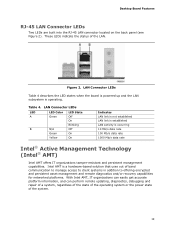
Desktop Board Features RJ-45 LAN Connector LEDs Two LEDs are built into the RJ-45 LAN connector located on the back panel (see Figure 2). These LEDs indicate the status of the system. 19 LAN Connector LEDs LED A B LED Color Green N/A Green Yellow LED... access to client systems in addition to offering encrypted and persistent asset management and remote diagnostics and/or recovery capabilities for networked platforms. With Intel AMT, IT organizations can easily get accurate platform information, and can perform remote updating, diagnostics, debugging and repair of a system, regardless...
Desktop Board Features RJ-45 LAN Connector LEDs Two LEDs are built into the RJ-45 LAN connector located on the back panel (see Figure 2). These LEDs indicate the status of the system. 19 LAN Connector LEDs LED A B LED Color Green N/A Green Yellow LED... access to client systems in addition to offering encrypted and persistent asset management and remote diagnostics and/or recovery capabilities for networked platforms. With Intel AMT, IT organizations can easily get accurate platform information, and can perform remote updating, diagnostics, debugging and repair of a system, regardless...

Product Guide
Page 21
...Intel® Matrix Storage Technology see Chapter 4. 21 Serial ATA RAID The ICH9DO supports the following RAID (Redundant Array of information between the processor and peripheral devices such as hard disk drives and CD-ROM drives. data striping • RAID 1 - USB 2.0 ports are backward compatible with USB 1.1 devices. Desktop Board... Features Hi-Speed USB 2.0 Support The Desktop Board supports up to 12 USB 2.0 ports (six ports routed to the back panel and six ports routed to three internal headers) via ICH9DO...
...Intel® Matrix Storage Technology see Chapter 4. 21 Serial ATA RAID The ICH9DO supports the following RAID (Redundant Array of information between the processor and peripheral devices such as hard disk drives and CD-ROM drives. data striping • RAID 1 - USB 2.0 ports are backward compatible with USB 1.1 devices. Desktop Board... Features Hi-Speed USB 2.0 Support The Desktop Board supports up to 12 USB 2.0 ports (six ports routed to the back panel and six ports routed to three internal headers) via ICH9DO...
Product Guide
Page 27
... PME# signal for PCI 2.3 compliant LAN designs • By Ping • Magic Packet • The onboard LAN subsystem Desktop Board DQ35JO supports waking the Intel Management Engine over the network. Failure to provide adequate standby current when using this feature can damage the power supply. Instantly Available... will appear to its last known awake state. 27 While in a low power state until a management console alert requests Intel AMT functionality. If the computer has a dual-colored power LED on the front panel, the sleep state is indicated by a wake-up the computer.
... PME# signal for PCI 2.3 compliant LAN designs • By Ping • Magic Packet • The onboard LAN subsystem Desktop Board DQ35JO supports waking the Intel Management Engine over the network. Failure to provide adequate standby current when using this feature can damage the power supply. Instantly Available... will appear to its last known awake state. 27 While in a low power state until a management console alert requests Intel AMT functionality. If the computer has a dual-colored power LED on the front panel, the sleep state is indicated by a wake-up the computer.

Product Guide
Page 31
2 Installing and Replacing Desktop Board Components This chapter tells you open the computer or perform any of the computer chassis. 31 Some circuitry on the board can continue to operate even though the front panel power button is not available, you begin: • Always follow the steps... to disconnect power, telecommunications links, networks, or modems before you how to: • Install the I/O shield • Install and remove the Desktop Board • Install and remove a processor • Install and remove memory • Install and remove a PCI Express x16 card • Connect ...
2 Installing and Replacing Desktop Board Components This chapter tells you open the computer or perform any of the computer chassis. 31 Some circuitry on the board can continue to operate even though the front panel power button is not available, you begin: • Always follow the steps... to disconnect power, telecommunications links, networks, or modems before you how to: • Install the I/O shield • Install and remove the Desktop Board • Install and remove a processor • Install and remove memory • Install and remove a PCI Express x16 card • Connect ...
Product Guide
Page 45
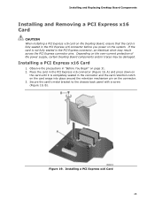
...panel with a screw (Figure 19, B). Figure 19. If the card is completely seated in the PCI Express connector, an electrical short may be damaged. Installing a PCI Express x16 Card 1. Observe the precautions in the PCI Express x16 connector before you power on the system. Installing and Replacing Desktop Board... Components Installing and Removing a PCI Express x16 Card CAUTION When installing a PCI Express x16 card on the Desktop Board, ensure that the card is fully seated in "Before You Begin...
...panel with a screw (Figure 19, B). Figure 19. If the card is completely seated in the PCI Express connector, an electrical short may be damaged. Installing a PCI Express x16 Card 1. Observe the precautions in the PCI Express x16 connector before you power on the system. Installing and Replacing Desktop Board... Components Installing and Removing a PCI Express x16 Card CAUTION When installing a PCI Express x16 card on the Desktop Board, ensure that the card is fully seated in "Before You Begin...
Product Guide
Page 46
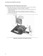
This will release the card from the connector: 1. Figure 20. Removing a PCI Express x16 Card 46 Push the card ejector lever down using the tip of a pencil or similar tool (Figure 20, B) in "Before You Begin" on page 31. 2. Pull the card straight up. Observe the precautions in the notch. Remove the screw (Figure 20, A) that secures the card's metal bracket to remove the PCI Express x16 card from the connector (C). 4. Intel Desktop Board DQ35JO Product Guide Removing the PCI Express x16 Card Follow these instructions to the chassis back panel. 3.
This will release the card from the connector: 1. Figure 20. Removing a PCI Express x16 Card 46 Push the card ejector lever down using the tip of a pencil or similar tool (Figure 20, B) in "Before You Begin" on page 31. 2. Pull the card straight up. Observe the precautions in the notch. Remove the screw (Figure 20, A) that secures the card's metal bracket to remove the PCI Express x16 card from the connector (C). 4. Intel Desktop Board DQ35JO Product Guide Removing the PCI Express x16 Card Follow these instructions to the chassis back panel. 3.
Product Guide
Page 49
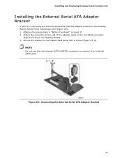
... 23. Installing and Replacing Desktop Board Components Installing the External Serial ATA Adapter Bracket If you are connecting the external Serial ATA (eSATA) adapter bracket to an internal SATA drive. Attach the connector at the end of the adapter cable to the chassis back panel with a screw (Figure... 23, A). Connecting the External Serial ATA Adapter Bracket 49 Secure the bracket to the red SATA connector (Figure 23, B) on page 31. 2. Observe the precautions in "Before You Begin" on the Desktop Board. 3.
... 23. Installing and Replacing Desktop Board Components Installing the External Serial ATA Adapter Bracket If you are connecting the external Serial ATA (eSATA) adapter bracket to an internal SATA drive. Attach the connector at the end of the adapter cable to the chassis back panel with a screw (Figure... 23, A). Connecting the External Serial ATA Adapter Bracket 49 Secure the bracket to the red SATA connector (Figure 23, B) on page 31. 2. Observe the precautions in "Before You Begin" on the Desktop Board. 3.
Product Guide
Page 50
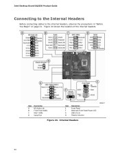
Figure 24 shows the location of the internal headers. Internal Headers 50 Intel Desktop Board DQ35JO Product Guide Connecting to the Internal Headers Before connecting cables to the internal headers, observe the precautions in "Before You Begin" on page 31. Item Description A HD Audio Link B Front Panel Audio C IEEE 1394a D Serial Port Item Description E Front Panel F Alternate Front Panel Power LED G USB 2.0 (3) H Chassis intrusion Figure 24.
Figure 24 shows the location of the internal headers. Internal Headers 50 Intel Desktop Board DQ35JO Product Guide Connecting to the Internal Headers Before connecting cables to the internal headers, observe the precautions in "Before You Begin" on page 31. Item Description A HD Audio Link B Front Panel Audio C IEEE 1394a D Serial Port Item Description E Front Panel F Alternate Front Panel Power LED G USB 2.0 (3) H Chassis intrusion Figure 24.
Product Guide
Page 51
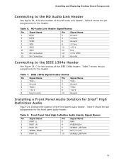
...(no pin) 8 +12 V 10 Ground Installing a Front Panel Audio Solution for Intel® High Definition Audio Figure 24, B shows the location of the front panel audio header. IEEE 1394a Signal Header Names Pin Signal Name 1... TPA1+ Pin Signal Name 2 TPA1- 3 Ground 4 Ground 5 TPA2+ 6 TPA2- 7 +12 V 9 Key (no pin) 10 SENSE2_RETURN 51 Table 8 shows the pin assignments for the header. Installing and Replacing Desktop Board...
...(no pin) 8 +12 V 10 Ground Installing a Front Panel Audio Solution for Intel® High Definition Audio Figure 24, B shows the location of the front panel audio header. IEEE 1394a Signal Header Names Pin Signal Name 1... TPA1+ Pin Signal Name 2 TPA1- 3 Ground 4 Ground 5 TPA2+ 6 TPA2- 7 +12 V 9 Key (no pin) 10 SENSE2_RETURN 51 Table 8 shows the pin assignments for the header. Installing and Replacing Desktop Board...
Product Guide
Page 52
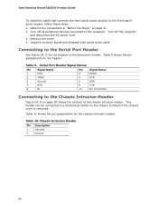
Turn off all peripheral devices connected to the computer. Install a correctly keyed and shielded front panel audio cable. Connecting to detect if the chassis cover is removed. This header can be connected to a mechanical switch on the chassis ... header, follow these steps: 1. Table 9 shows the pin assignments for the chassis intrusion header. Table 9. Intel Desktop Board DQ35JO Product Guide To install the cable that connects the front panel audio solution to the Chassis Intrusion Header Figure 24, H on page 50 shows the location of the serial port header. Observe the ...
Turn off all peripheral devices connected to the computer. Install a correctly keyed and shielded front panel audio cable. Connecting to detect if the chassis cover is removed. This header can be connected to a mechanical switch on the chassis ... header, follow these steps: 1. Table 9 shows the pin assignments for the chassis intrusion header. Table 9. Intel Desktop Board DQ35JO Product Guide To install the cable that connects the front panel audio solution to the Chassis Intrusion Header Figure 24, H on page 50 shows the location of the serial port header. Observe the ...
Product Guide
Page 53
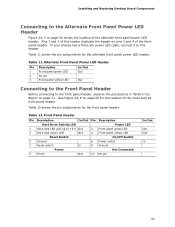
... In/Out Out Out Connecting to the Front Panel Header Before connecting to the Alternate Front Panel Power LED Header Figure 24, F on page 50 shows the location of the alternate front panel power LED header. Table 11. Installing and Replacing Desktop Board Components Connecting to the front panel header, observe the precautions in "Before You...
... In/Out Out Out Connecting to the Front Panel Header Before connecting to the Alternate Front Panel Power LED Header Figure 24, F on page 50 shows the location of the alternate front panel power LED header. Table 11. Installing and Replacing Desktop Board Components Connecting to the front panel header, observe the precautions in "Before You...

Product Guide
Page 54
...in B Audio line out C Mic in the table. Table 13. Back Panel Audio Connectors 54 Each USB header can be used to the Audio System After installing the RealTek audio driver from the Intel Express Installer DVD-ROM, the multi-channel audio feature can be assigned as...needed. Connecting to connect two USB devices. See Figure 24, G on page 31. The default connector assignments are shown in Figure 25. Intel Desktop Board DQ35JO Product Guide Connecting to the USB 2.0 Headers Before connecting to the USB 2.0 headers, observe the precautions in "Before You Begin" on ...
...in B Audio line out C Mic in the table. Table 13. Back Panel Audio Connectors 54 Each USB header can be used to the Audio System After installing the RealTek audio driver from the Intel Express Installer DVD-ROM, the multi-channel audio feature can be assigned as...needed. Connecting to connect two USB devices. See Figure 24, G on page 31. The default connector assignments are shown in Figure 25. Intel Desktop Board DQ35JO Product Guide Connecting to the USB 2.0 Headers Before connecting to the USB 2.0 headers, observe the precautions in "Before You Begin" on ...

Product Guide
Page 55
Connecting Chassis Fan and Power Supply Cables Connecting Chassis Fan Cables Connect chassis fan cables to power either headphones or amplified speakers only. Location of the chassis fan headers. Figure 26. Installing and Replacing Desktop Board Components NOTE The back panel audio line out connector is designed to the 3-pin chassis fan headers on the Desktop Board. Figure 26 shows the location of the Chassis Fan Headers 55 Poor audio quality may occur if passive (non-amplified) speakers are connected to this output.
Connecting Chassis Fan and Power Supply Cables Connecting Chassis Fan Cables Connect chassis fan cables to power either headphones or amplified speakers only. Location of the chassis fan headers. Figure 26. Installing and Replacing Desktop Board Components NOTE The back panel audio line out connector is designed to the 3-pin chassis fan headers on the Desktop Board. Figure 26 shows the location of the Chassis Fan Headers 55 Poor audio quality may occur if passive (non-amplified) speakers are connected to this output.


