
Product Guide
Page 7
...with Three DIMMs 39 18. Contents A Error Messages and Indicators BIOS Error Codes 71 BIOS Error Messages 72 Port 80h POST Codes 73 B Regulatory Compliance Safety Standards 77 Battery Caution 77 European Union Declaration of Conformity Statement 78 Product Ecology Statements 79...85 Ensure Electromagnetic Compatibility (EMC) Compliance 85 Product Certifications 86 Board-Level Certifications 86 Chassis- Installing the I/O Shield 31 8. Intel Desktop Board DP67BG Mounting Screw Hole Locations 32 9. Unlatch the Socket Lever 33 10. Lift the Load Plate 34 11. Remove the Processor ...
...with Three DIMMs 39 18. Contents A Error Messages and Indicators BIOS Error Codes 71 BIOS Error Messages 72 Port 80h POST Codes 73 B Regulatory Compliance Safety Standards 77 Battery Caution 77 European Union Declaration of Conformity Statement 78 Product Ecology Statements 79...85 Ensure Electromagnetic Compatibility (EMC) Compliance 85 Product Certifications 86 Board-Level Certifications 86 Chassis- Installing the I/O Shield 31 8. Intel Desktop Board DP67BG Mounting Screw Hole Locations 32 9. Unlatch the Socket Lever 33 10. Lift the Load Plate 34 11. Remove the Processor ...
Product Guide
Page 8
Intel Desktop Board DP67BG Components 13 3. BIOS Beep Codes 71 17. BIOS Error Messages 72 19. Connecting Power Supply Cables 54 28. Removing the Battery 62 30. POST Code LED Display 73 32. Front Panel CIR Receiver (Input) Header Signal Names 49 11. Regulatory Compliance Marks 86 viii Feature Summary 9 2. Audio Jack Retasking ...
Intel Desktop Board DP67BG Components 13 3. BIOS Beep Codes 71 17. BIOS Error Messages 72 19. Connecting Power Supply Cables 54 28. Removing the Battery 62 30. POST Code LED Display 73 32. Front Panel CIR Receiver (Input) Header Signal Names 49 11. Regulatory Compliance Marks 86 viii Feature Summary 9 2. Audio Jack Retasking ...
Product Guide
Page 13
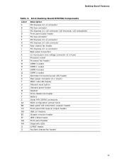
...3 socket DIMM 1 socket DIMM 4 socket DIMM 2 socket Alternate front panel power LED header Main power connector (2 x 12 pin) POST code LED display Onboard reset button Onboard power button Speaker Front chassis fan header Battery Serial ATA (SATA) connectors BIOS configuration jumper block ... CIR receiver (input) header USB 2.0 headers Chassis intrusion header IEEE 1394a header Front panel header Diagnostic LEDs S/PDIF header Auxiliary chassis fan header 13 Intel Desktop Board DP67BG Components Label A B C D E F G H I J K L M N O P Q R S T U V W X Y Z AA BB CC DD EE FF GG HH II JJ Description ...
...3 socket DIMM 1 socket DIMM 4 socket DIMM 2 socket Alternate front panel power LED header Main power connector (2 x 12 pin) POST code LED display Onboard reset button Onboard power button Speaker Front chassis fan header Battery Serial ATA (SATA) connectors BIOS configuration jumper block ... CIR receiver (input) header USB 2.0 headers Chassis intrusion header IEEE 1394a header Front panel header Diagnostic LEDs S/PDIF header Auxiliary chassis fan header 13 Intel Desktop Board DP67BG Components Label A B C D E F G H I J K L M N O P Q R S T U V W X Y Z AA BB CC DD EE FF GG HH II JJ Description ...
Product Guide
Page 19
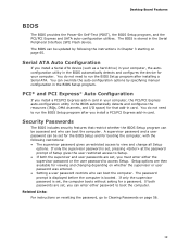
... by following restrictions: • The supervisor password gives unrestricted access to access Setup. Desktop Board Features BIOS The BIOS provides the Power-On Self-Test (POST), the BIOS Setup program, and the PCI/PCI Express and SATA auto-configuration utilities. PCI* and PCI Express* Auto Configuration If you install a PCI/PCI...
... by following restrictions: • The supervisor password gives unrestricted access to access Setup. Desktop Board Features BIOS The BIOS provides the Power-On Self-Test (POST), the BIOS Setup program, and the PCI/PCI Express and SATA auto-configuration utilities. PCI* and PCI Express* Auto Configuration If you install a PCI/PCI...
Product Guide
Page 27
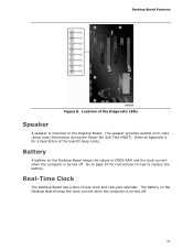
... computer is turned off . 27 Go to replace the battery. The speaker provides audible error code (beep code) information during the Power-On Self-Test (POST). Battery A battery on the Desktop Board keeps the clock current when the computer is mounted on how to page 57 for a description of the board...
... computer is turned off . 27 Go to replace the battery. The speaker provides audible error code (beep code) information during the Power-On Self-Test (POST). Battery A battery on the Desktop Board keeps the clock current when the computer is mounted on how to page 57 for a description of the board...

Product Guide
Page 35
... your fingers with the socket finger cutouts. Remove the processor from the socket. Remove the Processor from the Protective Cover 5. Hold the processor with the posts on the socket (Figure 12, C).
... your fingers with the socket finger cutouts. Remove the processor from the socket. Remove the Processor from the Protective Cover 5. Hold the processor with the posts on the socket (Figure 12, C).
Product Guide
Page 56
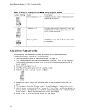
...cover. 4. Place the jumper on page 29. 2. Use the arrow keys to clear passwords. Configure (2-3) After the Power-On Self-Test (POST) runs, the BIOS displays the Maintenance Menu. Recovery (None) The BIOS recovers data in the computer, turn on the computer, and allow... displays the Maintenance menu. 8. Select Yes and press . Setup displays the maintenance menu again. 9. The computer starts the Setup program. Intel Desktop Board DP67BG Product Guide Table 15. Turn off the computer. Disconnect the computer's power cord from the AC power source (wall outlet or power adapter...
...cover. 4. Place the jumper on page 29. 2. Use the arrow keys to clear passwords. Configure (2-3) After the Power-On Self-Test (POST) runs, the BIOS displays the Maintenance Menu. Recovery (None) The BIOS recovers data in the computer, turn on the computer, and allow... displays the Maintenance menu. 8. Select Yes and press . Setup displays the maintenance menu again. 9. The computer starts the Setup program. Intel Desktop Board DP67BG Product Guide Table 15. Turn off the computer. Disconnect the computer's power cord from the AC power source (wall outlet or power adapter...
Product Guide
Page 65
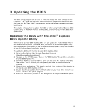
... tells you how to update the BIOS by pressing the key after the Power-On Self-Test (POST) memory test begins and before the operating system boot begins. Navigate to the Intel World Wide Web site Download Center at the last Express BIOS Update window. 5. Double-click the executable...removable USB device. You can update the system BIOS while in the dialog boxes to complete the BIOS update. 65 Go to the DP67BG page. Follow the instructions provided in the Windows environment. Close all other applications. Updating the BIOS with the Intel Express BIOS Update utility: 1.
... tells you how to update the BIOS by pressing the key after the Power-On Self-Test (POST) memory test begins and before the operating system boot begins. Navigate to the Intel World Wide Web site Download Center at the last Express BIOS Update window. 5. Double-click the executable...removable USB device. You can update the system BIOS while in the dialog boxes to complete the BIOS update. 65 Go to the DP67BG page. Follow the instructions provided in the Windows environment. Close all other applications. Updating the BIOS with the Intel Express BIOS Update utility: 1.

Product Guide
Page 67
... supplier or by navigating to the Intel Desktop Board DP67BG page on the computer's hard drive and without the need to remove the BIOS configuration jumper. Configure the BIOS or use the F10 option during POST to boot to upgrade the BIOS via the Intel Flash Memory Utility. 67 The image... uses ISOLINUX* bootloader and automatically launches a script to the USB device. 3. On the DP67BG page, click on the Intel World Wide Web site provides a simple method for ...
... supplier or by navigating to the Intel Desktop Board DP67BG page on the computer's hard drive and without the need to remove the BIOS configuration jumper. Configure the BIOS or use the F10 option during POST to boot to upgrade the BIOS via the Intel Flash Memory Utility. 67 The image... uses ISOLINUX* bootloader and automatically launches a script to the USB device. 3. On the DP67BG page, click on the Intel World Wide Web site provides a simple method for ...

Product Guide
Page 69
... Finally, press to the EXIT option in the RAID array (only if there are installed respectively). Creating Your RAID Set 1. In the Intel Rapid Storage Manager option ROM Main Menu, select option #1: Create RAID Volume. Select the drives to enter the RAID Configuration Utility. Exit ... interface by pressing or going to Create Volume. 8. Enter the size of your settings by pressing after the Power-On-Self-Test (POST) memory tests begin. 3. Enter a volume name (using English alphanumeric ASCII characters) and press . 3. Press and enter the RAID Configuration Utility. ...
... Finally, press to the EXIT option in the RAID array (only if there are installed respectively). Creating Your RAID Set 1. In the Intel Rapid Storage Manager option ROM Main Menu, select option #1: Create RAID Volume. Select the drives to enter the RAID Configuration Utility. Exit ... interface by pressing or going to Create Volume. 8. Enter the size of your settings by pressing after the Power-On-Self-Test (POST) memory tests begin. 3. Enter a volume name (using English alphanumeric ASCII characters) and press . 3. Press and enter the RAID Configuration Utility. ...
Product Guide
Page 71
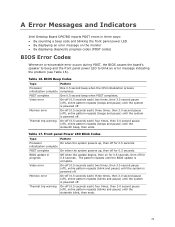
... second pause (off), entire pattern repeats (blink and pause) until the system is powered off. Table 16. A Error Messages and Indicators Intel Desktop Board DP67BG reports POST errors in progress Off when the update begins, then on the monitor • By displaying diagnostic progress codes... (POST codes) BIOS Error Codes Whenever a recoverable error occurs during POST, the BIOS causes the board's speaker to beep and the front panel power LED ...
... second pause (off), entire pattern repeats (blink and pause) until the system is powered off. Table 16. A Error Messages and Indicators Intel Desktop Board DP67BG reports POST errors in progress Off when the update begins, then on the monitor • By displaying diagnostic progress codes... (POST codes) BIOS Error Codes Whenever a recoverable error occurs during POST, the BIOS causes the board's speaker to beep and the front panel power LED ...
Product Guide
Page 72
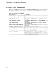
... decreased. The firmware has detected that a CMOS battery failure occurred. Maximum memory performance is required for reliable operation. Intel Desktop Board DP67BG Product Guide BIOS Error Messages When a recoverable error occurs during the POST, the BIOS displays an error message describing the problem. The firmware has detected that a CMOS Checksum Error occurred. The...
... decreased. The firmware has detected that a CMOS battery failure occurred. Maximum memory performance is required for reliable operation. Intel Desktop Board DP67BG Product Guide BIOS Error Messages When a recoverable error occurs during the POST, the BIOS displays an error message describing the problem. The firmware has detected that a CMOS Checksum Error occurred. The...
Product Guide
Page 73
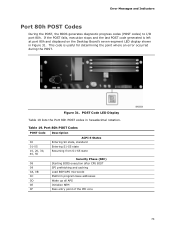
... 80h and displayed on the Desktop Board's seven-segment LED display shown in hexadecimal notation. POST Code LED Display Table 19 lists the Port 80h POST codes in Figure 31. Figure 31. Table 19. Port 80h POST Codes POST Code Description 00 01-05 10, 20, 30, 40, 50 ACPI S States Entering S0 state... caching Load BSP/APS microcode Platform program base addresses Wake up all APS Initialize NEM Pass entry point of the PEI core 73 If the POST fails, execution stops and the last POST code generated is useful for determining the point where an error occurred during the...
... 80h and displayed on the Desktop Board's seven-segment LED display shown in hexadecimal notation. POST Code LED Display Table 19 lists the Port 80h POST codes in Figure 31. Figure 31. Table 19. Port 80h POST Codes POST Code Description 00 01-05 10, 20, 30, 40, 50 ACPI S States Entering S0 state... caching Load BSP/APS microcode Platform program base addresses Wake up all APS Initialize NEM Pass entry point of the PEI core 73 If the POST fails, execution stops and the last POST code generated is useful for determining the point where an error occurred during the...
Product Guide
Page 74
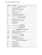
Intel Desktop Board DP67BG Product Guide POST Code 11 12 13 14 15 16 17, 18 19, 1A 1B, 1C 21 23 24 27 28 29 2A, 2B 31, 33, 34 41-...
Intel Desktop Board DP67BG Product Guide POST Code 11 12 13 14 15 16 17, 18 19, 1A 1B, 1C 21 23 24 27 28 29 2A, 2B 31, 33, 34 41-...
Product Specification
Page 3
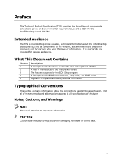
... important information. It is intended to provide detailed, technical information about the conventions used on the Intel Desktop Board DP67BG A map of the resources of the Intel Desktop Board The features supported by the BIOS Setup program A description of the BIOS error messages,... beep codes, and POST codes Regulatory compliance and battery disposal information Typographical Conventions This section contains information about the Intel Desktop Board DP67BG and its components to the vendors, system integrators, and other engineers ...
... important information. It is intended to provide detailed, technical information about the conventions used on the Intel Desktop Board DP67BG A map of the resources of the Intel Desktop Board The features supported by the BIOS Setup program A description of the BIOS error messages,... beep codes, and POST codes Regulatory compliance and battery disposal information Typographical Conventions This section contains information about the Intel Desktop Board DP67BG and its components to the vendors, system integrators, and other engineers ...
Product Specification
Page 6
Intel Desktop Board DP67BG Technical Product Specification 2.2 Connectors and Headers 41 2.2.1 Back Panel Connectors 42 2.2.2 Component-side Connectors and Headers 43 2.3 Jumper Block 52 2.4 Mechanical Considerations 54 2.4.1... BIOS Recovery 65 3.8 Boot Options 66 3.8.1 Optical Drive Boot 66 3.8.2 Network Boot 66 3.8.3 Booting Without Attached Devices 66 3.8.4 Changing the Default Boot Device During POST 66 3.9 Adjusting Boot Speed 67 3.9.1 Peripheral Selection and Configuration 67 3.9.2 BIOS Boot Optimizations 67 3.10 BIOS Security Features 68 3.11 BIOS Performance Features 69 4...
Intel Desktop Board DP67BG Technical Product Specification 2.2 Connectors and Headers 41 2.2.1 Back Panel Connectors 42 2.2.2 Component-side Connectors and Headers 43 2.3 Jumper Block 52 2.4 Mechanical Considerations 54 2.4.1... BIOS Recovery 65 3.8 Boot Options 66 3.8.1 Optical Drive Boot 66 3.8.2 Network Boot 66 3.8.3 Booting Without Attached Devices 66 3.8.4 Changing the Default Boot Device During POST 66 3.9 Adjusting Boot Speed 67 3.9.1 Peripheral Selection and Configuration 67 3.9.2 BIOS Boot Optimizations 67 3.10 BIOS Security Features 68 3.11 BIOS Performance Features 69 4...
Product Specification
Page 8
... 50 23. BIOS Setup Program Function Keys 62 30. Port 80h POST Codes 74 39. BIOS Setup Program Menu Bar 62 29. States for Components 58 27. Fan Header Current Capability 56 26. Environmental Specifications 59 28. Intel Desktop Board DP67BG Technical Product Specification 17. BIOS Setup Configuration Jumper Settings 53 24. AcceptableDrives...
... 50 23. BIOS Setup Program Function Keys 62 30. Port 80h POST Codes 74 39. BIOS Setup Program Menu Bar 62 29. States for Components 58 27. Fan Header Current Capability 56 26. Environmental Specifications 59 28. Intel Desktop Board DP67BG Technical Product Specification 17. BIOS Setup Configuration Jumper Settings 53 24. AcceptableDrives...
Product Specification
Page 12
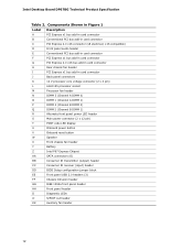
Intel Desktop Board DP67BG Technical Product Specification Table 2. Components Shown in Figure 1 Label Description A PCI Express x1 bus add-in card connector B Conventional PCI bus add-in ... 4 (Channel B DIMM 0) Q DIMM 2 (Channel B DIMM 1) R Alternate front panel power LED header S Main power connector (2 x 12 pin) T POST code LED display U Onboard power button V Onboard reset button W Speaker X Front chassis fan header Y Battery Z Intel P67 Express Chipset AA SATA connectors (6) BB Consumer IR transmitter (output) header CC Consumer IR receiver (input) header...
Intel Desktop Board DP67BG Technical Product Specification Table 2. Components Shown in Figure 1 Label Description A PCI Express x1 bus add-in card connector B Conventional PCI bus add-in ... 4 (Channel B DIMM 0) Q DIMM 2 (Channel B DIMM 1) R Alternate front panel power LED header S Main power connector (2 x 12 pin) T POST code LED display U Onboard power button V Onboard reset button W Speaker X Front chassis fan header Y Battery Z Intel P67 Express Chipset AA SATA connectors (6) BB Consumer IR transmitter (output) header CC Consumer IR receiver (input) header...

Product Specification
Page 21
...below a certain level, the BIOS Setup program settings stored in CMOS RAM (for example, the date and time) might not be notified during POST. The clock is designed to control external electronic hardware. Microsoft Windows Vista and Microsoft Windows 7 are required to buy or create their own ... battery and AC power fail date and time values will be reset and the user will be accurate. This learning input is not plugged into Intel Desktop Boards for the I/O controller. 1.8.1 Consumer Infrared (CIR) The Consumer Infrared (CIR) feature is accurate to work. 21 When the computer ...
...below a certain level, the BIOS Setup program settings stored in CMOS RAM (for example, the date and time) might not be notified during POST. The clock is designed to control external electronic hardware. Microsoft Windows Vista and Microsoft Windows 7 are required to buy or create their own ... battery and AC power fail date and time values will be reset and the user will be accurate. This learning input is not plugged into Intel Desktop Boards for the I/O controller. 1.8.1 Consumer Infrared (CIR) The Consumer Infrared (CIR) feature is accurate to work. 21 When the computer ...

Product Specification
Page 50
Table 21 shows the possible states for a two-color LED. When the switch is closed, the board resets and runs the POST. 2.2.2.4.3 Power/Sleep LED Header Pins 2 and 4 can be connected to internal debounce circuitry on the board.) At least two seconds must pull the SW_ON# ...Pins 6 and 8 can be connected to a momentary single pole, single throw (SPST) type switch that is due to a one -color LED. or two-color LED. Intel Desktop Board DP67BG Technical Product Specification 2.2.2.4.2 Reset Switch Header Pins 5 and 7 can be connected to a front panel momentary-contact power switch.
Table 21 shows the possible states for a two-color LED. When the switch is closed, the board resets and runs the POST. 2.2.2.4.3 Power/Sleep LED Header Pins 2 and 4 can be connected to internal debounce circuitry on the board.) At least two seconds must pull the SW_ON# ...Pins 6 and 8 can be connected to a momentary single pole, single throw (SPST) type switch that is due to a one -color LED. or two-color LED. Intel Desktop Board DP67BG Technical Product Specification 2.2.2.4.2 Reset Switch Header Pins 5 and 7 can be connected to a front panel momentary-contact power switch.


