
Product Guide
Page 5
Contents 1 Desktop Board Features Supported Operating Systems 11 Desktop Board Components 12 Processor ...14 Main Memory...15 Intel® P67 Express Chipset 16 Audio Subsystem 16 LAN Subsystem 17 USB Support ...18 Serial ATA Support 18 Legacy I/O ...18 Expandability...18 BIOS ...19 Serial... ATA Auto Configuration 19 PCI* and PCI Express* Auto Configuration 19 Security Passwords 19 Back to BIOS Button 20 Hardware Management 20 Hardware Monitoring and Fan Speed Control 20 Chassis Intrusion 21 Power Management 21 Software Support 21 ACPI 21 Hardware Support 21 Power Connectors 21...
Contents 1 Desktop Board Features Supported Operating Systems 11 Desktop Board Components 12 Processor ...14 Main Memory...15 Intel® P67 Express Chipset 16 Audio Subsystem 16 LAN Subsystem 17 USB Support ...18 Serial ATA Support 18 Legacy I/O ...18 Expandability...18 BIOS ...19 Serial... ATA Auto Configuration 19 PCI* and PCI Express* Auto Configuration 19 Security Passwords 19 Back to BIOS Button 20 Hardware Management 20 Hardware Monitoring and Fan Speed Control 20 Chassis Intrusion 21 Power Management 21 Software Support 21 ACPI 21 Hardware Support 21 Power Connectors 21...

Product Guide
Page 6
Intel Desktop Board DP67BG Product Guide Installing a Processor 33 Installing the Processor Fan Heat Sink 37 Connecting the Processor Fan Heat Sink Cable 37 Removing the Processor 37 Installing and Removing System Memory 38 Guidelines for Dual Channel Memory Configuration 38...Supply Cables 53 Connecting Chassis Fan Cables 53 Connecting Power Supply Cables 54 Setting the BIOS Configuration Jumper 55 Clearing Passwords 56 Replacing the Battery 57 Installing the WiFi/Bluetooth* Module in a Desktop Chassis 63 3 Updating the BIOS Updating the BIOS with the Intel® Express BIOS Update...
Intel Desktop Board DP67BG Product Guide Installing a Processor 33 Installing the Processor Fan Heat Sink 37 Connecting the Processor Fan Heat Sink Cable 37 Removing the Processor 37 Installing and Removing System Memory 38 Guidelines for Dual Channel Memory Configuration 38...Supply Cables 53 Connecting Chassis Fan Cables 53 Connecting Power Supply Cables 54 Setting the BIOS Configuration Jumper 55 Clearing Passwords 56 Replacing the Battery 57 Installing the WiFi/Bluetooth* Module in a Desktop Chassis 63 3 Updating the BIOS Updating the BIOS with the Intel® Express BIOS Update...
Product Guide
Page 7
... 12 2. Install the Processor 35 13. Connecting the Serial ATA Cables 46 24. Intel Desktop Board DP67BG Mounting Screw Hole Locations 32 9. Remove the Processor from the Protective Cover 35 12. Example Dual Channel Memory Configuration with Two DIMMs 38 ... 86 Board-Level Certifications 86 Chassis- Location of the Processor and Voltage Regulator LEDs 25 6. Location of the Diagnostic LEDs 27 7. Connecting the Processor Fan Heat Sink Power Cable to BIOS Button 20 4. Use DDR3 DIMMs 40 19. Installing a DIMM 41 20. Removing a PCI Express x16 Graphics Card...
... 12 2. Install the Processor 35 13. Connecting the Serial ATA Cables 46 24. Intel Desktop Board DP67BG Mounting Screw Hole Locations 32 9. Remove the Processor from the Protective Cover 35 12. Example Dual Channel Memory Configuration with Two DIMMs 38 ... 86 Board-Level Certifications 86 Chassis- Location of the Processor and Voltage Regulator LEDs 25 6. Location of the Diagnostic LEDs 27 7. Connecting the Processor Fan Heat Sink Power Cable to BIOS Button 20 4. Use DDR3 DIMMs 40 19. Installing a DIMM 41 20. Removing a PCI Express x16 Graphics Card...
Product Guide
Page 8
... Installing the WiFi/Bluetooth Module 64 31. Intel Desktop Board DP67BG China RoHS Material Self Declaration Table 82 Tables ...1. Alternate Front Panel Power LED Header Signal Names 49 10. Back Panel CIR Header Emitter (Output) Header Signal Names 50 12. Port 80h POST Codes 73 20. IEEE 1394a Header Signal Names 48 8. Intel Desktop Board DP67BG Components 13 3. BIOS Beep Codes 71 17. Intel... Desktop Board DP67BG Product Guide 25....
... Installing the WiFi/Bluetooth Module 64 31. Intel Desktop Board DP67BG China RoHS Material Self Declaration Table 82 Tables ...1. Alternate Front Panel Power LED Header Signal Names 49 10. Back Panel CIR Header Emitter (Output) Header Signal Names 50 12. Port 80h POST Codes 73 20. IEEE 1394a Header Signal Names 48 8. Intel Desktop Board DP67BG Components 13 3. BIOS Beep Codes 71 17. Intel... Desktop Board DP67BG Product Guide 25....
Product Guide
Page 10
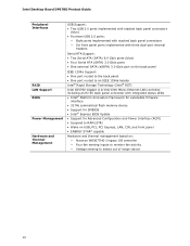
Intel Desktop Board DP67BG Product Guide Peripheral Interfaces RAID LAN Support BIOS Power Management Hardware and Thermal Management USB... One port routed to the back panel • One port routed to an IEEE 1394a header Intel® Rapid Storage Technology (Intel® RST) Intel 82579V Gigabit (10/100/1000 Mb/s) Ethernet LAN controller including an RJ-45 back panel connector ... STAR* capable Hardware and thermal management based on: ― Nuvoton W83677HG-I legacy I/O controller ― Four fan sensing inputs to monitor fan activity ― Voltage sensing to detect out of range values 10
Intel Desktop Board DP67BG Product Guide Peripheral Interfaces RAID LAN Support BIOS Power Management Hardware and Thermal Management USB... One port routed to the back panel • One port routed to an IEEE 1394a header Intel® Rapid Storage Technology (Intel® RST) Intel 82579V Gigabit (10/100/1000 Mb/s) Ethernet LAN controller including an RJ-45 back panel connector ... STAR* capable Hardware and thermal management based on: ― Nuvoton W83677HG-I legacy I/O controller ― Four fan sensing inputs to monitor fan activity ― Voltage sensing to detect out of range values 10
Product Guide
Page 13
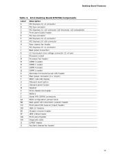
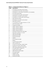
...LED header Main power connector (2 x 12 pin) POST code LED display Onboard reset button Onboard power button Speaker Front chassis fan header Battery Serial ATA (SATA) connectors BIOS configuration jumper block Back panel CIR transmitter (output) header Front panel CIR receiver... (input) header USB 2.0 headers Chassis intrusion header IEEE 1394a header Front panel header Diagnostic LEDs S/PDIF header Auxiliary chassis fan header 13 Desktop Board Features Table 2. Intel Desktop Board DP67BG Components Label A B C D E F G H I J K L M N O P Q R S T U V W X Y Z AA BB CC DD EE FF ...
...LED header Main power connector (2 x 12 pin) POST code LED display Onboard reset button Onboard power button Speaker Front chassis fan header Battery Serial ATA (SATA) connectors BIOS configuration jumper block Back panel CIR transmitter (output) header Front panel CIR receiver... (input) header USB 2.0 headers Chassis intrusion header IEEE 1394a header Front panel header Diagnostic LEDs S/PDIF header Auxiliary chassis fan header 13 Desktop Board Features Table 2. Intel Desktop Board DP67BG Components Label A B C D E F G H I J K L M N O P Q R S T U V W X Y Z AA BB CC DD EE FF ...
Product Guide
Page 20
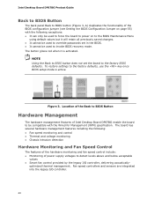
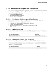
... monitoring and control • Thermal and voltage monitoring • Chassis intrusion detection Hardware Monitoring and Fan Speed Control The features of the hardware monitoring and fan speed control include: • Monitoring of Intel Desktop Board DP67BG enable the board to be compatible with the Wired for Management (WfM) specification. optimized thermal management. The button...
... monitoring and control • Thermal and voltage monitoring • Chassis intrusion detection Hardware Monitoring and Fan Speed Control The features of the hardware monitoring and fan speed control include: • Monitoring of Intel Desktop Board DP67BG enable the board to be compatible with the Wired for Management (WfM) specification. optimized thermal management. The button...
Product Guide
Page 21
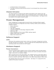
...Play functions of the power connectors. 21 Desktop Board Features • A thermal sensor in the processor • Thermally monitored closed-loop fan control, for all non-standby voltages. See Figure 27 on the Desktop Board. The use of the chassis intrusion header. The computer... off the computer power through the Advanced Configuration and Power Interface (ACPI) and the following hardware support: • Power connectors • Fan headers • LAN wake capabilities • Instantly Available PC technology (Suspend to the power state it was interrupted (either on or off...
...Play functions of the power connectors. 21 Desktop Board Features • A thermal sensor in the processor • Thermally monitored closed-loop fan control, for all non-standby voltages. See Figure 27 on the Desktop Board. The use of the chassis intrusion header. The computer... off the computer power through the Advanced Configuration and Power Interface (ACPI) and the following hardware support: • Power connectors • Fan headers • LAN wake capabilities • Instantly Available PC technology (Suspend to the power state it was interrupted (either on or off...

Product Guide
Page 22
... +5 V standby current. If the standby current necessary to support the standard Instantly Available (ACPI S3 sleep state) configuration. Intel Desktop Board DP67BG Product Guide Fan Headers The function/operation of the fans is as follows: • The fans are off as needed. • All fan headers have a +12 V DC connection. The Desktop Board has a 4-pin processor...
... +5 V standby current. If the standby current necessary to support the standard Instantly Available (ACPI S3 sleep state) configuration. Intel Desktop Board DP67BG Product Guide Fan Headers The function/operation of the fans is as follows: • The fans are off as needed. • All fan headers have a +12 V DC connection. The Desktop Board has a 4-pin processor...

Product Guide
Page 29
... Express x16 graphics card • Connect the Serial ATA cables • Connect to the internal headers • Connect to the audio system • Connect chassis fan and power supply cables • Set the BIOS configuration jumper • Clear passwords • Replace the battery • Install the WiFi/BlueTooth Module Before You...
... Express x16 graphics card • Connect the Serial ATA cables • Connect to the internal headers • Connect to the audio system • Connect chassis fan and power supply cables • Set the BIOS configuration jumper • Clear passwords • Replace the battery • Install the WiFi/BlueTooth Module Before You...
Product Guide
Page 37
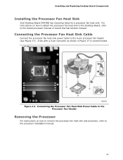
... Board Components Installing the Processor Fan Heat Sink Intel Desktop Board DP67BG has mounting holes for a processor fan heat sink. For instructions on how to remove the processor fan heat sink and processor, refer to the processor installation manual. 37 Connecting the Processor Fan Heat Sink Power Cable to the Processor Fan Header Removing the Processor For...
... Board Components Installing the Processor Fan Heat Sink Intel Desktop Board DP67BG has mounting holes for a processor fan heat sink. For instructions on how to remove the processor fan heat sink and processor, refer to the processor installation manual. 37 Connecting the Processor Fan Heat Sink Power Cable to the Processor Fan Header Removing the Processor For...
Product Guide
Page 53
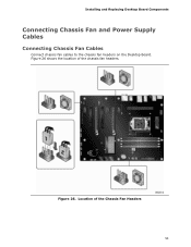
Figure 26. Installing and Replacing Desktop Board Components Connecting Chassis Fan and Power Supply Cables Connecting Chassis Fan Cables Connect chassis fan cables to the chassis fan headers on the Desktop Board. Location of the chassis fan headers. Figure 26 shows the location of the Chassis Fan Headers 53
Figure 26. Installing and Replacing Desktop Board Components Connecting Chassis Fan and Power Supply Cables Connecting Chassis Fan Cables Connect chassis fan cables to the chassis fan headers on the Desktop Board. Location of the chassis fan headers. Figure 26 shows the location of the Chassis Fan Headers 53
Product Specification
Page 5
... Board Layout 11 1.1.3 Block Diagram 13 1.2 Legacy Considerations 14 1.3 Online Support 14 1.4 Processor 14 1.5 System Memory 15 1.5.1 Memory Configurations 17 1.6 Intel® P67 Express Chipset 19 1.6.1 PCI Express x16 Graphics 19 1.6.2 USB 19 1.6.3 SATA Interfaces 19 1.7 Real-Time Clock Subsystem 21 1.8 Legacy I/O... 26 1.11.2 WiFi 802.11 Wireless (Module 26 1.12 Hardware Management Subsystem 27 1.12.1 Hardware Monitoring and Fan Control 27 1.12.2 Fan Monitoring 27 1.12.3 Chassis Intrusion and Detection 27 1.12.4 Thermal Monitoring 28 1.13 Power Management 29 1.13.1...
... Board Layout 11 1.1.3 Block Diagram 13 1.2 Legacy Considerations 14 1.3 Online Support 14 1.4 Processor 14 1.5 System Memory 15 1.5.1 Memory Configurations 17 1.6 Intel® P67 Express Chipset 19 1.6.1 PCI Express x16 Graphics 19 1.6.2 USB 19 1.6.3 SATA Interfaces 19 1.7 Real-Time Clock Subsystem 21 1.8 Legacy I/O... 26 1.11.2 WiFi 802.11 Wireless (Module 26 1.12 Hardware Management Subsystem 27 1.12.1 Hardware Monitoring and Fan Control 27 1.12.2 Fan Monitoring 27 1.12.3 Chassis Intrusion and Detection 27 1.12.4 Thermal Monitoring 28 1.13 Power Management 29 1.13.1...
Product Specification
Page 6
Intel Desktop Board DP67BG Technical Product Specification 2.2 Connectors and Headers 41 2.2.1 Back Panel Connectors 42 2.2.2 Component-side Connectors and Headers 43 2.3 Jumper Block 52 2.4 Mechanical Considerations 54 2.4.1 Form Factor 54 2.5 Electrical Considerations 55 2.5.1 Power Supply Considerations 55 2.5.2 Fan Header Current Capability 56 2.5.3 Add-in Board Considerations 56 2.6 Thermal Considerations 57 2.7 Reliability 59 2.8 Environmental 59...
Intel Desktop Board DP67BG Technical Product Specification 2.2 Connectors and Headers 41 2.2.1 Back Panel Connectors 42 2.2.2 Component-side Connectors and Headers 43 2.3 Jumper Block 52 2.4 Mechanical Considerations 54 2.4.1 Form Factor 54 2.5 Electrical Considerations 55 2.5.1 Power Supply Considerations 55 2.5.2 Fan Header Current Capability 56 2.5.3 Add-in Board Considerations 56 2.6 Thermal Considerations 57 2.7 Reliability 59 2.8 Environmental 59...
Product Specification
Page 7
... 35 95H 275H 8. Major Board Components 11 89H 269H 2. LAN Connector LED Locations 25 93H 273H 6. Diagnostic LEDs 36 13H 293H 10. Thermal Sensors and Fan Headers 28 94H 274H 7. Component-side Connectors and Headers 43 9H 279H 12. Location of Conformity Statement 80 5.1.3 Product Ecology Statements 81 5.1.4 EMC Regulations 83...
... 35 95H 275H 8. Major Board Components 11 89H 269H 2. LAN Connector LED Locations 25 93H 273H 6. Diagnostic LEDs 36 13H 293H 10. Thermal Sensors and Fan Headers 28 94H 274H 7. Component-side Connectors and Headers 43 9H 279H 12. Location of Conformity Statement 80 5.1.3 Product Ecology Statements 81 5.1.4 EMC Regulations 83...
Product Specification
Page 8
... 324H viii Processor Core Power Connector 48 19. Recommended Power Supply Current Values 55 25. Fan Header Current Capability 56 26. Front-panel Power LED Blink Codes 72 35. EMC Regulations 83 32H 41. Intel Desktop Board DP67BG Technical Product Specification 17. Thermal Considerations for BIOS Recovery 65 31. BIOS Setup Program Function...
... 324H viii Processor Core Power Connector 48 19. Recommended Power Supply Current Values 55 25. Fan Header Current Capability 56 26. Front-panel Power LED Blink Codes 72 35. EMC Regulations 83 32H 41. Intel Desktop Board DP67BG Technical Product Specification 17. Thermal Considerations for BIOS Recovery 65 31. BIOS Setup Program Function...

Product Specification
Page 10
... Wake on PCI, PCI Express, LAN, front panel, CIR, and USB ports Gigabit (10/100/1000 Mbits/s) LAN subsystem using the Intel® 82579V Gigabit Ethernet Controller • Two PCI Express 2.0 x16 • Three PCI Express x1 bus add-in card connectors from ... fan headers using PWM control • Four fan sense inputs used to monitor fan activity • Fan speed control using voltage control (4-pin fan headers front, rear, and auxiliary) with selectable support in BIOS for 3 wire fans • Support for Platform Environmental Control Interface (PECI) 10 Intel Desktop Board DP67BG Technical...
... Wake on PCI, PCI Express, LAN, front panel, CIR, and USB ports Gigabit (10/100/1000 Mbits/s) LAN subsystem using the Intel® 82579V Gigabit Ethernet Controller • Two PCI Express 2.0 x16 • Three PCI Express x1 bus add-in card connectors from ... fan headers using PWM control • Four fan sense inputs used to monitor fan activity • Fan speed control using voltage control (4-pin fan headers front, rear, and auxiliary) with selectable support in BIOS for 3 wire fans • Support for Platform Environmental Control Interface (PECI) 10 Intel Desktop Board DP67BG Technical...
Product Specification
Page 12
Intel Desktop Board DP67BG Technical Product Specification Table 2. Components Shown in Figure 1 Label Description A PCI Express x1 bus add-in card connector B Conventional PCI bus add-in card connector J Back panel connectors K 12 V processor core voltage connector (2 x 4 pin) L LGA1155 processor socket M Processor fan header... T POST code LED display U Onboard power button V Onboard reset button W Speaker X Front chassis fan header Y Battery Z Intel P67 Express Chipset AA SATA connectors (6) BB Consumer IR transmitter (output) header CC Consumer IR receiver (...
Intel Desktop Board DP67BG Technical Product Specification Table 2. Components Shown in Figure 1 Label Description A PCI Express x1 bus add-in card connector B Conventional PCI bus add-in card connector J Back panel connectors K 12 V processor core voltage connector (2 x 4 pin) L LGA1155 processor socket M Processor fan header... T POST code LED display U Onboard power button V Onboard reset button W Speaker X Front chassis fan header Y Battery Z Intel P67 Express Chipset AA SATA connectors (6) BB Consumer IR transmitter (output) header CC Consumer IR receiver (...
Product Specification
Page 27
... board to be implemented using Intel® Desktop Control Center or third-party software. When the chassis cover is removed, the mechanical switch is removed. The board has several hardware management features, including the following: • Fan monitoring and control •... the following: • Processor and system ambient temperature monitoring • Chassis fan speed monitoring • Power monitoring of +12 V, +5 V, +3.3 V, V_SM and +VCCP • SMBus interface 1.12.2 Fan Monitoring Fan monitoring can be compatible with the Wired for Management (WfM) specification. For ...
... board to be implemented using Intel® Desktop Control Center or third-party software. When the chassis cover is removed, the mechanical switch is removed. The board has several hardware management features, including the following: • Fan monitoring and control •... the following: • Processor and system ambient temperature monitoring • Chassis fan speed monitoring • Power monitoring of +12 V, +5 V, +3.3 V, V_SM and +VCCP • SMBus interface 1.12.2 Fan Monitoring Fan monitoring can be compatible with the Wired for Management (WfM) specification. For ...

Product Specification
Page 28
Thermal Sensors and Fan Headers 28 Item A B C D E F G Description Rear chassis fan header Voltage regulator thermal diode Thermal diode, located on processor die Processor fan header Front chassis fan header Thermal diode, located on the Intel P67 Express Chipset Auxiliary fan header Figure 6. Intel Desktop Board DP67BG Technical Product Specification 1.12.4 Thermal Monitoring Figure 6 shows the locations of the thermal sensors and fan headers.
Thermal Sensors and Fan Headers 28 Item A B C D E F G Description Rear chassis fan header Voltage regulator thermal diode Thermal diode, located on processor die Processor fan header Front chassis fan header Thermal diode, located on the Intel P67 Express Chipset Auxiliary fan header Figure 6. Intel Desktop Board DP67BG Technical Product Specification 1.12.4 Thermal Monitoring Figure 6 shows the locations of the thermal sensors and fan headers.


