
Product Specification
Page 6
... Features 3.1 Introduction 61 3.2 System Management BIOS (SMBIOS 63 3.3 Legacy USB Support 63 3.4 BIOS Updates 64 3.4.1 Language Support 64 3.4.2 Custom Splash Screen 65 3.5 BIOS Recovery 65 3.6 Boot Options 66 3.6.1 Optical Drive Boot 66 3.6.2 Network Boot 66 3.6.3 Booting Without Attached Devices 66 3.6.4 Changing the Default Boot Device During POST 66 3.7 BIOS Security Features 67 4 Error Messages and Beep Codes 4.1 Speaker 69 4.2 BIOS Beep Codes 69 4.3 Front-panel Power LED Blink Codes 70 4.4 BIOS Error Messages 70 4.5 Port 80h POST Codes 71 5 Regulatory Compliance and...
... Features 3.1 Introduction 61 3.2 System Management BIOS (SMBIOS 63 3.3 Legacy USB Support 63 3.4 BIOS Updates 64 3.4.1 Language Support 64 3.4.2 Custom Splash Screen 65 3.5 BIOS Recovery 65 3.6 Boot Options 66 3.6.1 Optical Drive Boot 66 3.6.2 Network Boot 66 3.6.3 Booting Without Attached Devices 66 3.6.4 Changing the Default Boot Device During POST 66 3.7 BIOS Security Features 67 4 Error Messages and Beep Codes 4.1 Speaker 69 4.2 BIOS Beep Codes 69 4.3 Front-panel Power LED Blink Codes 70 4.4 BIOS Error Messages 70 4.5 Port 80h POST Codes 71 5 Regulatory Compliance and...

Product Specification
Page 7
... Tables 1. Supported Memory Configurations 15 4. LAN Connector LED States 24 8. Power States and Targeted System Power 29 10. Component-side Connectors and Headers Shown in Figure 1 12 3. Front Panel Audio Header for Front Panel Header 48 12. Intel HD Audio Link Header 44 18. System Memory Map 39 12. Block Diagram 13 3. Processor (4-Pin) Fan Header 45 22. Contents Figures 1. Back Panel Audio Connectors 22 5. Location of the Standby Power LED 34 8. Back Panel Connectors 40 10. Connection Diagram for Intel HD Audio 43 16. Board Dimensions...
... Tables 1. Supported Memory Configurations 15 4. LAN Connector LED States 24 8. Power States and Targeted System Power 29 10. Component-side Connectors and Headers Shown in Figure 1 12 3. Front Panel Audio Header for Front Panel Header 48 12. Intel HD Audio Link Header 44 18. System Memory Map 39 12. Block Diagram 13 3. Processor (4-Pin) Fan Header 45 22. Contents Figures 1. Back Panel Audio Connectors 22 5. Location of the Standby Power LED 34 8. Back Panel Connectors 40 10. Connection Diagram for Intel HD Audio 43 16. Board Dimensions...
Product Specification
Page 8
.... Boot Device Menu Options 66 41. Front-panel Power LED Blink Codes 70 44. Port 80h POST Codes 72 47. Thermal Considerations for a One-Color Power LED 49 30. Acceptable Drives/Media Types for Components 58 36. BIOS Beep Codes 69 43. Port 80h POST Code Ranges 71 46. BIOS Setup Configuration Jumper Settings 52 32. BIOS Setup Program Menu Bar 62 38. Supervisor and User Password Functions 67 42. BIOS Error Messages 70 45. Safety Standards 77 49. Intel Desktop Board DH57DD Technical Product Specification 28. Typical Port...
.... Boot Device Menu Options 66 41. Front-panel Power LED Blink Codes 70 44. Port 80h POST Codes 72 47. Thermal Considerations for a One-Color Power LED 49 30. Acceptable Drives/Media Types for Components 58 36. BIOS Beep Codes 69 43. Port 80h POST Code Ranges 71 46. BIOS Setup Configuration Jumper Settings 52 32. BIOS Setup Program Menu Bar 62 38. Supervisor and User Password Functions 67 42. BIOS Error Messages 70 45. Safety Standards 77 49. Intel Desktop Board DH57DD Technical Product Specification 28. Typical Port...
Product Specification
Page 12
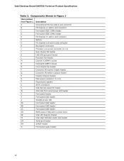
... R Chassis intrusion header S Main power connector (2 x 12) T Piezoelectric speaker U SATA connectors V Intel Remote Assist PC header W Alternate front panel power LED header X Front panel header Y Front panel USB header Z Standby power LED AA Front panel USB header BB Front panel USB header CC Front panel USB header DD BIOS setup configuration jumper block EE Intel H57 Express Chipset FF Intel High Definition Audio Link header GG Serial port header HH S/PDIF header II Front panel audio header 12 Intel Desktop Board DH57DD Technical Product Specification...
... R Chassis intrusion header S Main power connector (2 x 12) T Piezoelectric speaker U SATA connectors V Intel Remote Assist PC header W Alternate front panel power LED header X Front panel header Y Front panel USB header Z Standby power LED AA Front panel USB header BB Front panel USB header CC Front panel USB header DD BIOS setup configuration jumper block EE Intel H57 Express Chipset FF Intel High Definition Audio Link header GG Serial port header HH S/PDIF header II Front panel audio header 12 Intel Desktop Board DH57DD Technical Product Specification...
Product Specification
Page 18
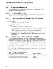
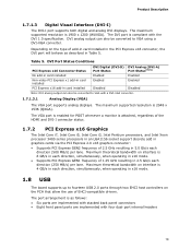
... a PCI Express 2.0 x16 add-in graphics card. 1.7.1 Integrated Graphics The board supports integrated graphics through the Intel® Flexible Display Interface (FDI) for POST whenever a monitor is attached, regardless of the VGA and DVI-I connector status. Depending on a single cable. The HDMI port is enabled for processors with Intel HD Graphics. 1.7.1.1 Intel® High Definition Graphics (Intel® HD Graphics) The Intel HD graphics controller features the following: • 3D Features ⎯ DirectX10* and OpenGL* 2.1 compliant ⎯ Shader Model 4.0 • Video...
... a PCI Express 2.0 x16 add-in graphics card. 1.7.1 Integrated Graphics The board supports integrated graphics through the Intel® Flexible Display Interface (FDI) for POST whenever a monitor is attached, regardless of the VGA and DVI-I connector status. Depending on a single cable. The HDMI port is enabled for processors with Intel HD Graphics. 1.7.1.1 Intel® High Definition Graphics (Intel® HD Graphics) The Intel HD graphics controller features the following: • 3D Features ⎯ DirectX10* and OpenGL* 2.1 compliant ⎯ Shader Model 4.0 • Video...
Product Specification
Page 19
... Connector Status No add-in card installed Non-video PCI Express x1 add-in card installed PCI Express x16 add-in each direction (250 MB/s) per lane. The VGA port is enabled for POST whenever a monitor is 8 GB/s in card installed DVI Digital (DVI-D) Port Status Enabled Enabled DVI Analog (DVI-A) Port Status(Note) Enabled Enabled Disabled Disabled Note: DVI analog output can also be converted to VGA using a DVI-VGA converter. The port arrangement is compliant with four dual-port internal headers...
... Connector Status No add-in card installed Non-video PCI Express x1 add-in card installed PCI Express x16 add-in each direction (250 MB/s) per lane. The VGA port is enabled for POST whenever a monitor is 8 GB/s in card installed DVI Digital (DVI-D) Port Status Enabled Enabled DVI Analog (DVI-A) Port Status(Note) Enabled Enabled Disabled Disabled Note: DVI analog output can also be converted to VGA using a DVI-VGA converter. The port arrangement is compliant with four dual-port internal headers...
Product Specification
Page 28
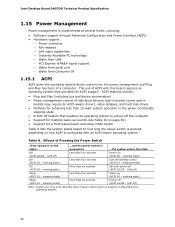
...; Software support through Advanced Configuration and Power Interface (ACPI) • Hardware support: ⎯ Power connector ⎯ Fan headers ⎯ LAN wake capabilities ⎯ Instantly Available PC technology ⎯ Wake from USB ⎯ PCI Express WAKE# signal support ⎯ Wake from serial port ⎯ Wake from Consumer IR 1.15.1 ACPI ACPI gives the operating system direct control over the power management and Plug and Play functions of individual devices, add-in boards (some add-in boards may require an ACPI-aware driver), video displays, and hard disk drives •...
...; Software support through Advanced Configuration and Power Interface (ACPI) • Hardware support: ⎯ Power connector ⎯ Fan headers ⎯ LAN wake capabilities ⎯ Instantly Available PC technology ⎯ Wake from USB ⎯ PCI Express WAKE# signal support ⎯ Wake from serial port ⎯ Wake from Consumer IR 1.15.1 ACPI ACPI gives the operating system direct control over the power management and Plug and Play functions of individual devices, add-in boards (some add-in boards may require an ACPI-aware driver), video displays, and hard disk drives •...
Product Specification
Page 50
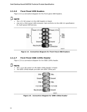
... header provides one IEEE 1394a port. NOTE • The +12 V DC power on the USB headers is a connection diagram for the front panel USB headers. Figure 13. Figure 12. Connection Diagram for the IEEE 1394a header. Intel Desktop Board DH57DD Technical Product Specification 2.2.2.6 Front Panel USB Headers Figure 12 is fused. • Use only a front panel USB connector that conforms to the USB 2.0 specification for high-speed USB devices. NOTE • The +5 V DC power on the IEEE 1394a header is a connection diagram for IEEE 1394a Header...
... header provides one IEEE 1394a port. NOTE • The +12 V DC power on the USB headers is a connection diagram for the front panel USB headers. Figure 13. Figure 12. Connection Diagram for the IEEE 1394a header. Intel Desktop Board DH57DD Technical Product Specification 2.2.2.6 Front Panel USB Headers Figure 12 is fused. • Use only a front panel USB connector that conforms to the USB 2.0 specification for high-speed USB devices. NOTE • The +5 V DC power on the IEEE 1394a header is a connection diagram for IEEE 1394a Header...
Product Specification
Page 70
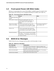
Intel Desktop Board DH57DD Technical Product Specification 4.3 Front-panel Power LED Blink Codes Whenever a recoverable error occurs during POST, the BIOS causes the board's front panel power LED to reset values. The pattern repeats until the BIOS update is powered off. Run Setup to blink an error message describing the problem (see Table 43). This will be bad. Replace the battery soon. CMOS memory may be losing power. No Boot Device Available System did not find a device to boot. 70 Table 43. Video error (no...
Intel Desktop Board DH57DD Technical Product Specification 4.3 Front-panel Power LED Blink Codes Whenever a recoverable error occurs during POST, the BIOS causes the board's front panel power LED to reset values. The pattern repeats until the BIOS update is powered off. Run Setup to blink an error message describing the problem (see Table 43). This will be bad. Replace the battery soon. CMOS memory may be losing power. No Boot Device Available System did not find a device to boot. 70 Table 43. Video error (no...

Product Specification
Page 71
... POST code generated is an unrecoverable error. Start with PCI. 60 - 6F Reserved for future use (for new busses). 70 - 7F Output Devices: All output consoles. 7F is an unrecoverable error. 80 - 8F Reserved for debug. 10 - 1F Host Processors: 1F is an unrecoverable CPU error. 20 - 2F Memory/Chipset: 2F is no memory detected or no useful memory detected. 30 - 3F 40 - 4F Recovery: 3F indicated recovery failure...
... POST code generated is an unrecoverable error. Start with PCI. 60 - 6F Reserved for future use (for new busses). 70 - 7F Output Devices: All output consoles. 7F is an unrecoverable error. 80 - 8F Reserved for debug. 10 - 1F Host Processors: 1F is an unrecoverable CPU error. 20 - 2F Memory/Chipset: 2F is no memory detected or no useful memory detected. 30 - 3F 40 - 4F Recovery: 3F indicated recovery failure...
Product Specification
Page 75
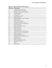
Error Messages and Beep Codes Table 47. Typical Port 80h POST Sequence POST Code Description 21 Initializing a chipset component 22 Reading SPD from memory DIMMs 23 Detecting presence of memory DIMMs 25 Configuring memory 28 Testing memory 34 Loading recovery capsule E4 Entered DXE phase 12 Starting application processor initialization 13 SMM initialization 50 Enumerating PCI busses 51 Allocating resourced to PCI bus 92 Detecting the presence of the keyboard 90 Resetting keyboard 94 Clearing keyboard input...
Error Messages and Beep Codes Table 47. Typical Port 80h POST Sequence POST Code Description 21 Initializing a chipset component 22 Reading SPD from memory DIMMs 23 Detecting presence of memory DIMMs 25 Configuring memory 28 Testing memory 34 Loading recovery capsule E4 Entered DXE phase 12 Starting application processor initialization 13 SMM initialization 50 Enumerating PCI busses 51 Allocating resourced to PCI bus 92 Detecting the presence of the keyboard 90 Resetting keyboard 94 Clearing keyboard input...
Intel Desktop Board DH57DD Product Guide English
Page 3
... of product features 2 Installing and Replacing Desktop Board Components: instructions on how to important information. Document Organization The chapters in homes, offices, schools, computer rooms, and similar locations. Use Only for Intel® Desktop Board DH57DD. iii It is intended for general audiences. may not be supported without further evaluation by Intel. Preface This Product Guide gives information about BIOS error messages and beep codes B Regulatory Compliance: describes...
... of product features 2 Installing and Replacing Desktop Board Components: instructions on how to important information. Document Organization The chapters in homes, offices, schools, computer rooms, and similar locations. Use Only for Intel® Desktop Board DH57DD. iii It is intended for general audiences. may not be supported without further evaluation by Intel. Preface This Product Guide gives information about BIOS error messages and beep codes B Regulatory Compliance: describes...
Intel Desktop Board DH57DD Product Guide English
Page 5
... 15 Main Memory...15 Graphics Subsystem 16 Integrated Graphics 16 Intel® HD Graphics 16 High-Definition Multimedia Interface* (HDMI 16 Digital Visual Interface (DVI-I 17 VGA Displays 17 PCI Express* x16 Graphics 17 Audio Subsystem 18 LAN Subsystem 19 USB 2.0 Support 19 SATA Support...20 Expandability...20 Legacy I/O ...20 BIOS ...20 SATA Auto Configuration 20 PCI*/PCI Express Auto Configuration 21 Security Passwords 21 Hardware Management 21 Hardware Monitoring and Fan Speed Control 21 Fan Monitoring 22 Chassis Intrusion 22 Power Management 22 Software Support 22 ACPI...
... 15 Main Memory...15 Graphics Subsystem 16 Integrated Graphics 16 Intel® HD Graphics 16 High-Definition Multimedia Interface* (HDMI 16 Digital Visual Interface (DVI-I 17 VGA Displays 17 PCI Express* x16 Graphics 17 Audio Subsystem 18 LAN Subsystem 19 USB 2.0 Support 19 SATA Support...20 Expandability...20 Legacy I/O ...20 BIOS ...20 SATA Auto Configuration 20 PCI*/PCI Express Auto Configuration 21 Security Passwords 21 Hardware Management 21 Hardware Monitoring and Fan Speed Control 21 Fan Monitoring 22 Chassis Intrusion 22 Power Management 22 Software Support 22 ACPI...
Intel Desktop Board DH57DD Product Guide English
Page 6
...a PCI Express x16 Graphics Card 43 Connecting SATA Cables 44 Connecting to the Internal Headers 45 Front Panel Audio Header 46 IEEE 1394a Headers 46 S/PDIF Header 47 Serial Header 47 Consumer IR (CIR) Headers 47 Intel® RPAT Header 48 Chassis Intrusion Header 48 Alternate Front Panel Power LED Header 49 Front Panel Header 49 Front Panel USB 2.0 Headers 50 HD Audio Link Header 50 Connecting to the Audio System 51 Connecting Chassis Fan and Power Supply Cables 52 Connecting a Chassis Fan 52 Connecting Power Supply Cables 53 Setting the BIOS Configuration Jumper 54 Clearing...
...a PCI Express x16 Graphics Card 43 Connecting SATA Cables 44 Connecting to the Internal Headers 45 Front Panel Audio Header 46 IEEE 1394a Headers 46 S/PDIF Header 47 Serial Header 47 Consumer IR (CIR) Headers 47 Intel® RPAT Header 48 Chassis Intrusion Header 48 Alternate Front Panel Power LED Header 49 Front Panel Header 49 Front Panel USB 2.0 Headers 50 HD Audio Link Header 50 Connecting to the Audio System 51 Connecting Chassis Fan and Power Supply Cables 52 Connecting a Chassis Fan 52 Connecting Power Supply Cables 53 Setting the BIOS Configuration Jumper 54 Clearing...
Intel Desktop Board DH57DD Product Guide English
Page 7
... Load Plate 35 12. Example Dual Channel Memory Configuration with Two DIMMs 37 15. Connecting a SATA Cable 44 vii Example Dual Channel Memory Configuration with Four DIMMs 38 16. Use DDR3 DIMMs 39 18. Install the Processor 34 11. Installing a DIMM 40 19. Lift the Load Plate 32 8. Example Dual Channel Memory Configuration with Three DIMMs 38 17. Installing a PCI Express x16 Graphics Card 42 20. Installing the I/O Shield 29 5. Intel Desktop Board DH57DD Components 12 2. Contents A Error Messages and Indicators BIOS Error Codes 67 BIOS Error...
... Load Plate 35 12. Example Dual Channel Memory Configuration with Two DIMMs 37 15. Connecting a SATA Cable 44 vii Example Dual Channel Memory Configuration with Four DIMMs 38 16. Use DDR3 DIMMs 39 18. Install the Processor 34 11. Installing a DIMM 40 19. Lift the Load Plate 32 8. Example Dual Channel Memory Configuration with Three DIMMs 38 17. Installing a PCI Express x16 Graphics Card 42 20. Installing the I/O Shield 29 5. Intel Desktop Board DH57DD Components 12 2. Contents A Error Messages and Indicators BIOS Error Codes 67 BIOS Error...
Intel Desktop Board DH57DD Product Guide English
Page 8
.... Location of the BIOS Configuration Jumper Block 54 27. Front-panel Power LED Blink Codes 68 23. Audio Jack Retasking Support 18 6. Front Panel Audio Header Signal Names for Intel HD Audio 46 8. BIOS Error Messages 68 24. BIOS Beep Codes 67 22. Intel Desktop Board DH57DD China RoHS Material Self Declaration Table 74 Tables 1. Regulatory Compliance Marks 78 viii Internal Headers 45 23. Intel RPAT Header Signal Names 48 15. HDMI Port Status Conditions 16 4. Jumper Settings for the BIOS Setup Program Modes 55...
.... Location of the BIOS Configuration Jumper Block 54 27. Front-panel Power LED Blink Codes 68 23. Audio Jack Retasking Support 18 6. Front Panel Audio Header Signal Names for Intel HD Audio 46 8. BIOS Error Messages 68 24. BIOS Beep Codes 67 22. Intel Desktop Board DH57DD China RoHS Material Self Declaration Table 74 Tables 1. Regulatory Compliance Marks 78 viii Internal Headers 45 23. Intel RPAT Header Signal Names 48 15. HDMI Port Status Conditions 16 4. Jumper Settings for the BIOS Setup Program Modes 55...
Intel Desktop Board DH57DD Product Guide English
Page 20
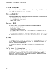
... can override the auto-configuration options by following the instructions in the Serial Peripheral Interface (SPI) Flash device. SATA Auto Configuration If you install a SATA device (such as a hard drive) in your computer. Expandability Intel Desktop Board DH57DD provides the following legacy features: • Low pin count (LPC) interface • One serial port header • Consumer Infrared (CIR) support • Serial IRQ interface compatible with serialized IRQ support for PCI Conventional bus systems • Intelligent power management, including a programmable wake-up event...
... can override the auto-configuration options by following the instructions in the Serial Peripheral Interface (SPI) Flash device. SATA Auto Configuration If you install a SATA device (such as a hard drive) in your computer. Expandability Intel Desktop Board DH57DD provides the following legacy features: • Low pin count (LPC) interface • One serial port header • Consumer Infrared (CIR) support • Serial IRQ interface compatible with serialized IRQ support for PCI Conventional bus systems • Intelligent power management, including a programmable wake-up event...
Intel Desktop Board DH57DD Product Guide English
Page 27
... panel power button is not available, you can damage components. 2 Installing and Replacing Desktop Board Components This chapter tells you how to: • Install the I/O shield • Install and remove the Desktop Board • Install and remove a processor • Install and remove memory • Install and remove a PCI Express x16 card • Connect SATA cables • Connect to the internal headers • Connect to the audio system • Connect chassis fan and power supply cables • Set the BIOS configuration jumper • Clear passwords • Replace the battery...
... panel power button is not available, you can damage components. 2 Installing and Replacing Desktop Board Components This chapter tells you how to: • Install the I/O shield • Install and remove the Desktop Board • Install and remove a processor • Install and remove memory • Install and remove a PCI Express x16 card • Connect SATA cables • Connect to the internal headers • Connect to the audio system • Connect chassis fan and power supply cables • Set the BIOS configuration jumper • Clear passwords • Replace the battery...
Intel Desktop Board DH57DD Product Guide English
Page 55
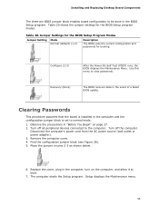
.... Installing and Replacing Desktop Board Components The three-pin BIOS jumper block enables board configuration to boot. 7. Configure (2-3) After the Power-On Self-Test (POST) runs, the BIOS displays the Maintenance Menu. Clearing Passwords This procedure assumes that the board is installed in the event of a failed BIOS update. Turn off all peripheral devices connected to the computer. Remove the computer cover. 4. Setup displays the Maintenance menu. 55 Jumper Settings for the BIOS Setup Program Modes Jumper Setting Mode Normal (default) (1-2) Description The BIOS uses...
.... Installing and Replacing Desktop Board Components The three-pin BIOS jumper block enables board configuration to boot. 7. Configure (2-3) After the Power-On Self-Test (POST) runs, the BIOS displays the Maintenance Menu. Clearing Passwords This procedure assumes that the board is installed in the event of a failed BIOS update. Turn off all peripheral devices connected to the computer. Remove the computer cover. 4. Setup displays the Maintenance menu. 55 Jumper Settings for the BIOS Setup Program Modes Jumper Setting Mode Normal (default) (1-2) Description The BIOS uses...
Intel Desktop Board DH57DD Product Guide English
Page 63
... file to a removable USB device. This runs the update program. 6. This chapter tells you are updating the BIOS for the computer. The BIOS file is included in the Windows environment. You can access the BIOS Setup program by either using the Intel Express BIOS Update utility or the Intel® Flash Memory Update Utility, and how to your hard drive where it was saved. Under the "Software and drivers" heading, click on the "BIOS Update" link and select the Express BIOS Update file. 3. Download the file...
... file to a removable USB device. This runs the update program. 6. This chapter tells you are updating the BIOS for the computer. The BIOS file is included in the Windows environment. You can access the BIOS Setup program by either using the Intel Express BIOS Update utility or the Intel® Flash Memory Update Utility, and how to your hard drive where it was saved. Under the "Software and drivers" heading, click on the "BIOS Update" link and select the Express BIOS Update file. 3. Download the file...


