

Product Guide
Page 6
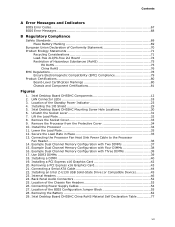
Intel Desktop Board DH55HC Product Guide 2 Installing and Replacing Desktop Board Components Before You Begin 27 ...47 S/PDIF Header 48 Parallel Port Header 48 Chassis Intrusion Header 49 Intel® RPAT Header 49 Alternate Front Panel Power LED Header 49 Front Panel Header 50 Front Panel USB 2.0 Headers 50 Serial Header 51 Connecting to the Audio System 52... Configuration Jumper 55 Clearing Passwords 56 Replacing the Battery 57 3 Updating the BIOS Updating the BIOS with the Intel® Express BIOS Update Utility 63 Updating the BIOS with the ISO Image BIOS Update File or the Iflash...
Intel Desktop Board DH55HC Product Guide 2 Installing and Replacing Desktop Board Components Before You Begin 27 ...47 S/PDIF Header 48 Parallel Port Header 48 Chassis Intrusion Header 49 Intel® RPAT Header 49 Alternate Front Panel Power LED Header 49 Front Panel Header 50 Front Panel USB 2.0 Headers 50 Serial Header 51 Connecting to the Audio System 52... Configuration Jumper 55 Clearing Passwords 56 Replacing the Battery 57 3 Updating the BIOS Updating the BIOS with the Intel® Express BIOS Update Utility 63 Updating the BIOS with the ISO Image BIOS Update File or the Iflash...
Product Guide
Page 7
...DIMMs 38 17. Example Dual Channel Memory Configuration with Two DIMMs 37 15. Location of the Standby Power Indicator 23 4. Intel Desktop Board DH55HC China RoHS Material Self Declaration Table 77 vii LAN Connector LEDs 18 3. Connecting a Serial ATA Cable 44 22. Internal... 35 12. Example Dual Channel Memory Configuration with Four DIMMs 38 16. Installing a DIMM 40 19. Intel Desktop Board DH55HC Mounting Screw Hole Locations 30 6. Back Panel Audio Connectors 52 25. Contents A Error Messages and Indicators BIOS Error Codes 67 BIOS Error Messages 68 ...
...DIMMs 38 17. Example Dual Channel Memory Configuration with Two DIMMs 37 15. Location of the Standby Power Indicator 23 4. Intel Desktop Board DH55HC China RoHS Material Self Declaration Table 77 vii LAN Connector LEDs 18 3. Connecting a Serial ATA Cable 44 22. Internal... 35 12. Example Dual Channel Memory Configuration with Four DIMMs 38 16. Installing a DIMM 40 19. Intel Desktop Board DH55HC Mounting Screw Hole Locations 30 6. Back Panel Audio Connectors 52 25. Contents A Error Messages and Indicators BIOS Error Codes 67 BIOS Error Messages 68 ...
Product Guide
Page 8
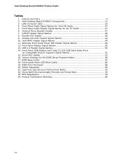
... LEDs 18 4. Intel RPAT Header Signal Names 49 11. Chassis Intrusion Header Signal Names 49 10. Safety Standards 69 21. Internal Mono Speaker Header 47 7. Intel Desktop Board DH55HC Components 13 3. Serial Port Header 51 16. BIOS Error Messages 68 20. Front Panel Audio Header Signal... Names for AC '97 Audio 47 6. Intel Desktop Board DH55HC Product Guide Tables 1.
... LEDs 18 4. Intel RPAT Header Signal Names 49 11. Chassis Intrusion Header Signal Names 49 10. Safety Standards 69 21. Internal Mono Speaker Header 47 7. Intel Desktop Board DH55HC Components 13 3. Serial Port Header 51 16. BIOS Error Messages 68 20. Front Panel Audio Header Signal... Names for AC '97 Audio 47 6. Intel Desktop Board DH55HC Product Guide Tables 1.
Product Guide
Page 10
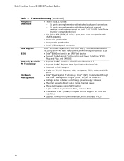
Intel Desktop Board DH55HC Product Guide Table 1. Feature Summary (continued) Peripheral Interfaces LAN Support BIOS • Twelve USB 2.0 ports: ― Six ports are implemented with stacked back panel connectors ― Six ports are implemented with integrated status LEDs • Intel® BIOS resident in ...to RAM support • Wake on PCI, PCI Express, LAN, front panel, PS/2, serial, and USB ports • Intel® Quiet System Technology (Intel® QST) implemented through the Intel® Management Engine (Intel® ME) in the H55 PCH • Voltage sense to detect out...
Intel Desktop Board DH55HC Product Guide Table 1. Feature Summary (continued) Peripheral Interfaces LAN Support BIOS • Twelve USB 2.0 ports: ― Six ports are implemented with stacked back panel connectors ― Six ports are implemented with integrated status LEDs • Intel® BIOS resident in ...to RAM support • Wake on PCI, PCI Express, LAN, front panel, PS/2, serial, and USB ports • Intel® Quiet System Technology (Intel® QST) implemented through the Intel® Management Engine (Intel® ME) in the H55 PCH • Voltage sense to detect out...
Product Guide
Page 13
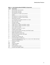
Intel Desktop Board DH55HC Components Label A B C D E F G H I J K L M N O P Q R S T U V W X Y Z AA BB CC DD EE Description PCI bus add-in card connector PCI bus add-in connector PCI bus add-in connector PCI Express 2.0 x1 add-in card connector Battery PCI Express 2.0 x1 add-in card connector PCI Express 2.0 x16 add-in card connector Back panel connectors 12...
Intel Desktop Board DH55HC Components Label A B C D E F G H I J K L M N O P Q R S T U V W X Y Z AA BB CC DD EE Description PCI bus add-in card connector PCI bus add-in connector PCI bus add-in connector PCI Express 2.0 x1 add-in card connector Battery PCI Express 2.0 x1 add-in card connector PCI Express 2.0 x16 add-in card connector Back panel connectors 12...
Product Guide
Page 17
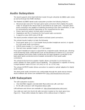
... • A signal-to-noise (S/N) ratio of 90 dB The board provides onboard audio headers and back panel connectors. Desktop Board Features Audio Subsystem The board supports Intel High Definition Audio through a Realtek ALC888S audio codec as well as simultaneous 6-channel (5.1) surround sound playback and... of 8 Ω at 1 W (rms) or 4 Ω at http://downloadcenter.intel.com/. The onboard audio headers include the following features: • Advanced jack sense for the back panel audio connectors that enables the audio codec to recognize the device that provides headphone and mic in...
... • A signal-to-noise (S/N) ratio of 90 dB The board provides onboard audio headers and back panel connectors. Desktop Board Features Audio Subsystem The board supports Intel High Definition Audio through a Realtek ALC888S audio codec as well as simultaneous 6-channel (5.1) surround sound playback and... of 8 Ω at 1 W (rms) or 4 Ω at http://downloadcenter.intel.com/. The onboard audio headers include the following features: • Advanced jack sense for the back panel audio connectors that enables the audio codec to recognize the device that provides headphone and mic in...
Product Guide
Page 18
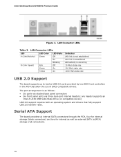
... connectors) and two for internal as well as follows: • Six ports via stacked back panel connectors • Six front panel ports via three dual-port internal headers; The port arrangement is occurring 10 Mb/s data rate ...by two EHCI host controllers in the PCH that fully support USB 2.0 transfer rates. one header supports an Intel Z-U130 USB Solid-State Drive (or compatible device) USB 2.0 support requires both an operating system and ...is as external SATA (eSATA) storage (red connectors). 18 Intel Desktop Board DH55HC Product Guide Figure 2. LAN Connector LEDs Table 3.
... connectors) and two for internal as well as follows: • Six ports via stacked back panel connectors • Six front panel ports via three dual-port internal headers; The port arrangement is occurring 10 Mb/s data rate ...by two EHCI host controllers in the PCH that fully support USB 2.0 transfer rates. one header supports an Intel Z-U130 USB Solid-State Drive (or compatible device) USB 2.0 support requires both an operating system and ...is as external SATA (eSATA) storage (red connectors). 18 Intel Desktop Board DH55HC Product Guide Figure 2. LAN Connector LEDs Table 3.
Product Guide
Page 22
Intel Desktop Board DH55HC Product Guide Fan Headers The function/operation of delivering adequate +5 V standby current. Instantly Available PC technology enables the board to -RAM) sleep-state. LAN Wake ... is off as configured by Pulse Width Modulation. • The front and rear chassis fans support Linear Fan Control on or off and the front panel power LED will appear to its last known wake state. When signaled by a wake-up the computer.
Intel Desktop Board DH55HC Product Guide Fan Headers The function/operation of delivering adequate +5 V standby current. Instantly Available PC technology enables the board to -RAM) sleep-state. LAN Wake ... is off as configured by Pulse Width Modulation. • The front and rear chassis fans support Linear Fan Control on or off and the front panel power LED will appear to its last known wake state. When signaled by a wake-up the computer.
Product Guide
Page 27
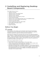
...open the computer or perform any of the computer chassis. 27 Some circuitry on the board can continue to operate even though the front panel power button is not available, you can provide some ESD protection by wearing an antistatic wrist strap and attaching it to a metal ...remove a processor • Install and remove memory • Install and remove a PCI Express x16 card • Connect Serial ATA cables • Install an Intel Z-U130 USB Solid-State Drive (or Compatible Device) • Connect to the internal headers and connectors • Connect to the audio system • Connect ...
...open the computer or perform any of the computer chassis. 27 Some circuitry on the board can continue to operate even though the front panel power button is not available, you can provide some ESD protection by wearing an antistatic wrist strap and attaching it to a metal ...remove a processor • Install and remove memory • Install and remove a PCI Express x16 card • Connect Serial ATA cables • Install an Intel Z-U130 USB Solid-State Drive (or Compatible Device) • Connect to the internal headers and connectors • Connect to the audio system • Connect ...

Product Guide
Page 41
... the PCI Express graphics card if one was removed in "Before You Begin" on page 27. 2. Secure the card's metal bracket to the chassis back panel with a screw (Figure 19, B). 41
... the PCI Express graphics card if one was removed in "Before You Begin" on page 27. 2. Secure the card's metal bracket to the chassis back panel with a screw (Figure 19, B). 41

Product Guide
Page 42
Intel Desktop Board DH55HC Product Guide 4. Observe the precautions in the notch. Remove the screw (Figure 20, A) that secures the card's metal bracket to the manufacturer's instructions. Push the ... (Figure 20, B) in "Before You Begin" on page 27. 2. Connect a monitor to the graphics card according to the chassis back panel. 4. This will release the card from the graphics card back panel connector. 3. Pull the card straight up to remove a PCI Express x16 graphics card from a connector: 1. Disconnect the monitor cable from...
Intel Desktop Board DH55HC Product Guide 4. Observe the precautions in the notch. Remove the screw (Figure 20, A) that secures the card's metal bracket to the manufacturer's instructions. Push the ... (Figure 20, B) in "Before You Begin" on page 27. 2. Connect a monitor to the graphics card according to the chassis back panel. 4. This will release the card from the graphics card back panel connector. 3. Pull the card straight up to remove a PCI Express x16 graphics card from a connector: 1. Disconnect the monitor cable from...

Product Guide
Page 45
... USB Solid-State Drive (or compatible device) on the Desktop Board, follow these steps: 1. Installing an Intel Z-U130 USB Solid-State Drive (or Compatible Device) If not used with an Intel Z-U130 USB Solid-State Drive (or Compatible Device), this USB header can be used as shown in "... when the solid state drive is oriented as an additional dual-port front panel USB header. 45 Installing and Replacing Desktop Board Components Installing an Intel® Z-U130 USB Solid-State Drive (or Compatible Device) An Intel Z-U130 USB Solid-State Drive (or compatible device) can be installed on...
... USB Solid-State Drive (or compatible device) on the Desktop Board, follow these steps: 1. Installing an Intel Z-U130 USB Solid-State Drive (or Compatible Device) If not used with an Intel Z-U130 USB Solid-State Drive (or Compatible Device), this USB header can be used as shown in "... when the solid state drive is oriented as an additional dual-port front panel USB header. 45 Installing and Replacing Desktop Board Components Installing an Intel® Z-U130 USB Solid-State Drive (or Compatible Device) An Intel Z-U130 USB Solid-State Drive (or compatible device) can be installed on...

Product Guide
Page 47
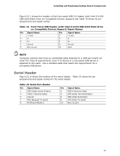
...) 10 FP_RETURN_L Internal Mono Speaker Header The internal mono speaker header is shown in Figure 23, A supports both Intel High Definition (HD) Audio and AC '97 Audio. Front Panel Audio Signal Names for the internal mono speaker header. Installing and Replacing Desktop Board Components Front... Panel Audio Header The front panel audio header shown in Figure 23, B. Internal Mono Speaker Header Pin Signal Name 1 − 2 + 47 Table 4. Front Panel Audio Header Signal Names for AC '97 Audio. Table...
...) 10 FP_RETURN_L Internal Mono Speaker Header The internal mono speaker header is shown in Figure 23, A supports both Intel High Definition (HD) Audio and AC '97 Audio. Front Panel Audio Signal Names for the internal mono speaker header. Installing and Replacing Desktop Board Components Front... Panel Audio Header The front panel audio header shown in Figure 23, B. Internal Mono Speaker Header Pin Signal Name 1 − 2 + 47 Table 4. Front Panel Audio Header Signal Names for AC '97 Audio. Table...

Product Guide
Page 49
... location of the alternate front panel power LED header. Intel RPAT Header Signal Names Pin Description 1 RPAT# 2 Ground Alternate Front Panel Power LED Header Figure 23, G shows the location of the Intel RPAT header. Pins 1 and 3 of this header. Alternate Front Panel Power LED Header Signal Names ...Pin Signal Name 1 Front panel LED+ 2 No pin 3 Front panel LED- In/Out Out Out...
... location of the alternate front panel power LED header. Intel RPAT Header Signal Names Pin Description 1 RPAT# 2 Ground Alternate Front Panel Power LED Header Figure 23, G shows the location of the Intel RPAT header. Pins 1 and 3 of this header. Alternate Front Panel Power LED Header Signal Names ...Pin Signal Name 1 Front panel LED+ 2 No pin 3 Front panel LED- In/Out Out Out...

Product Guide
Page 50
...from your chassis front panel to the front panel header, be sure to +5 V Out 2 Front panel LED+ 3 Hard disk active LED Out 4 Front panel LED- Table 12 shows the pin assignments and signal names for the front panel header. Intel Desktop Board DH55HC Product Guide Front Panel Header Figure 23, ...H shows the location of the standard front panel USB 2.0 header and Table 13 shows its pin assignments and signal names. Front Panel Header Signal Names Pin Description In...
...from your chassis front panel to the front panel header, be sure to +5 V Out 2 Front panel LED+ 3 Hard disk active LED Out 4 Front panel LED- Table 12 shows the pin assignments and signal names for the front panel header. Intel Desktop Board DH55HC Product Guide Front Panel Header Figure 23, ...H shows the location of the standard front panel USB 2.0 header and Table 13 shows its pin assignments and signal names. Front Panel Header Signal Names Pin Description In...
Product Guide
Page 51
Serial Header Figure 23, K shows the location of the front panel USB 2.0 header (with Intel Z-U130 USB Solid-State Drive (or Compatible Device) Support) Signal Names Pin Signal Name 1 +5 VDC 3 D- 5 D+ 7 Ground 9 KEY (no pin) Pin Signal Name 2 +5 VDC 4 D- 6 D+ 8... cable attached to the cable. Table 15 shows the pin assignments and signal names for a full-speed USB device. Table 14. Front Panel USB Header (with Intel Z-U130 USB Solid-State Drive (or Compatible Device) Support) and Table 14 shows its pin assignments and signal names. Installing and Replacing ...
Serial Header Figure 23, K shows the location of the front panel USB 2.0 header (with Intel Z-U130 USB Solid-State Drive (or Compatible Device) Support) Signal Names Pin Signal Name 1 +5 VDC 3 D- 5 D+ 7 Ground 9 KEY (no pin) Pin Signal Name 2 +5 VDC 4 D- 6 D+ 8... cable attached to the cable. Table 15 shows the pin assignments and signal names for a full-speed USB device. Table 14. Front Panel USB Header (with Intel Z-U130 USB Solid-State Drive (or Compatible Device) Support) and Table 14 shows its pin assignments and signal names. Installing and Replacing ...

Product Guide
Page 52
Intel Desktop Board DH55HC Product Guide Connecting to power either headphones or amplified speakers only. Figure 24 shows the back panel audio connectors. The default connector assignments are connected to this output. 52 Back Panel Audio Connectors NOTE The back panel line out connector is ...designed to the Audio System After installing the Realtek audio driver from the Intel® Express Installer DVD-ROM, the multi-channel audio...
Intel Desktop Board DH55HC Product Guide Connecting to power either headphones or amplified speakers only. Figure 24 shows the back panel audio connectors. The default connector assignments are connected to this output. 52 Back Panel Audio Connectors NOTE The back panel line out connector is ...designed to the Audio System After installing the Realtek audio driver from the Intel® Express Installer DVD-ROM, the multi-channel audio...

Product Guide
Page 67
Table 17. A Error Messages and Indicators Intel Desktop Board DH55HC reports POST errors in two ways: • By sounding a beep code and blinking the front panel power LED • By displaying an error message on the monitor BIOS Error Codes Whenever a recoverable error occurs during POST, the BIOS causes the board's ...
Table 17. A Error Messages and Indicators Intel Desktop Board DH55HC reports POST errors in two ways: • By sounding a beep code and blinking the front panel power LED • By displaying an error message on the monitor BIOS Error Codes Whenever a recoverable error occurs during POST, the BIOS causes the board's ...

Product Guide
Page 68
... Messages When a recoverable error occurs during the POST, the BIOS displays an error message describing the problem. Table 19. The CMOS checksum is complete. Front-panel Power LED Blink Codes Type F2 Setup/F10 Boot Menu Prompt BIOS update in progress Video error (no memory was removed, then memory may be... system is powered off . CMOS memory may be accompanied by the following blink pattern: .25 seconds on, .25 seconds off, .25 seconds on for 0.5 seconds. Intel Desktop Board DH55HC Product Guide Table 18.
... Messages When a recoverable error occurs during the POST, the BIOS displays an error message describing the problem. Table 19. The CMOS checksum is complete. Front-panel Power LED Blink Codes Type F2 Setup/F10 Boot Menu Prompt BIOS update in progress Video error (no memory was removed, then memory may be... system is powered off . CMOS memory may be accompanied by the following blink pattern: .25 seconds on, .25 seconds off, .25 seconds on for 0.5 seconds. Intel Desktop Board DH55HC Product Guide Table 18.

Intel Desktop Board DH55HC Technical Product Specification
Page 6
Intel Desktop Board DH55HC Technical Product Specification 2.2 Connectors and Headers 37 2.2.1 Back Panel Connectors 38 2.2.2 Component-side Connectors and Headers 39 2.3 Jumper Block 49 2.4 Mechanical Considerations 51 2.4.1 Form Factor 51 2.5 Electrical Considerations ...Default Boot Device During POST 64 3.7 BIOS Security Features 65 4 Error Messages and Beep Codes 4.1 Speaker 67 4.2 BIOS Beep Codes 67 4.3 Front-panel Power LED Blink Codes 68 4.4 BIOS Error Messages 68 4.5 Port 80h POST Codes 69 5 Regulatory Compliance and Battery Disposal Information 5.1 Regulatory Compliance ...
Intel Desktop Board DH55HC Technical Product Specification 2.2 Connectors and Headers 37 2.2.1 Back Panel Connectors 38 2.2.2 Component-side Connectors and Headers 39 2.3 Jumper Block 49 2.4 Mechanical Considerations 51 2.4.1 Form Factor 51 2.5 Electrical Considerations ...Default Boot Device During POST 64 3.7 BIOS Security Features 65 4 Error Messages and Beep Codes 4.1 Speaker 67 4.2 BIOS Beep Codes 67 4.3 Front-panel Power LED Blink Codes 68 4.4 BIOS Error Messages 68 4.5 Port 80h POST Codes 69 5 Regulatory Compliance and Battery Disposal Information 5.1 Regulatory Compliance ...


