
Product Specification
Page 6
...68 3.3.2 PCI IDE Support 69 3.4 System Management BIOS (SMBIOS 69 3.5 Legacy USB Support 70 3.6 BIOS Updates 70 3.6.1 Language Support 71 3.6.2 Custom Splash Screen 71 3.7 BIOS Recovery 71 3.8 Boot Options 72 3.8.1 CD-ROM Boot 72 3.8.2 Network Boot 72 3.8.3 Booting Without Attached Devices 72 3.8.4 Changing the Default Boot Device During POST 72 3.9 Adjusting Boot Speed 73 3.9.1 Peripheral Selection and Configuration 73 3.9.2 BIOS Boot Optimizations 73 3.10 BIOS Security Features 74 4 Error Messages and Beep Codes 4.1 Speaker 75 4.2 BIOS Beep Codes 75 4.3 BIOS Error Messages...
...68 3.3.2 PCI IDE Support 69 3.4 System Management BIOS (SMBIOS 69 3.5 Legacy USB Support 70 3.6 BIOS Updates 70 3.6.1 Language Support 71 3.6.2 Custom Splash Screen 71 3.7 BIOS Recovery 71 3.8 Boot Options 72 3.8.1 CD-ROM Boot 72 3.8.2 Network Boot 72 3.8.3 Booting Without Attached Devices 72 3.8.4 Changing the Default Boot Device During POST 72 3.9 Adjusting Boot Speed 73 3.9.1 Peripheral Selection and Configuration 73 3.9.2 BIOS Boot Optimizations 73 3.10 BIOS Security Features 74 4 Error Messages and Beep Codes 4.1 Speaker 75 4.2 BIOS Beep Codes 75 4.3 BIOS Error Messages...

Product Specification
Page 7
.../Back Panel Audio Connector Options 30 11. Location of Pressing the Power Switch 35 8. Feature Summary 10 2. Memory Operating Frequencies 17 5. Audio Jack Retasking Support 29 6. Effects of the Jumper Block 58 21. System Memory Map 43 vii Single Channel (Asymmetric) Mode Configuration with Three DIMMs ......... 19 6. Thermal Sensors and Fan Headers 34 13. Connection Diagram for IEEE 1394a Header 57 20. LAN Connector LED States 32 7. Power States and Targeted System Power 36 9. Dual Channel (Interleaved) Mode Configuration with...
.../Back Panel Audio Connector Options 30 11. Location of Pressing the Power Switch 35 8. Feature Summary 10 2. Memory Operating Frequencies 17 5. Audio Jack Retasking Support 29 6. Effects of the Jumper Block 58 21. System Memory Map 43 vii Single Channel (Asymmetric) Mode Configuration with Three DIMMs ......... 19 6. Thermal Sensors and Fan Headers 34 13. Connection Diagram for IEEE 1394a Header 57 20. LAN Connector LED States 32 7. Power States and Targeted System Power 36 9. Dual Channel (Interleaved) Mode Configuration with...
Product Specification
Page 8
.... Serial Port Header 52 22. Front and Rear Chassis Fan Headers 53 24. Front Panel Header 55 28. BIOS Setup Configuration Jumper Settings 58 31. Boot Device Menu Options 72 39. Port 80h POST Code Ranges 76 43. I/O Map 44 13. Component-side Connectors and Headers Shown in Figure 16 51 18. Processor Core Power Connector 54 26. DC Loading Characteristics 61 32. BIOS Setup Program Menu Bar 68 36. BIOS Setup Program Function Keys 68 37. BIOS Error Messages 75 42. Port 80h POST Codes 77 44. PCI Configuration...
.... Serial Port Header 52 22. Front and Rear Chassis Fan Headers 53 24. Front Panel Header 55 28. BIOS Setup Configuration Jumper Settings 58 31. Boot Device Menu Options 72 39. Port 80h POST Code Ranges 76 43. I/O Map 44 13. Component-side Connectors and Headers Shown in Figure 16 51 18. Processor Core Power Connector 54 26. DC Loading Characteristics 61 32. BIOS Setup Program Menu Bar 68 36. BIOS Setup Program Function Keys 68 37. BIOS Error Messages 75 42. Port 80h POST Codes 77 44. PCI Configuration...
Product Specification
Page 10
...Wake on PCI, RS-232, front panel, PS/2 devices, and USB ports continued 10 Intel Desktop Board DG965RY Technical Product Specification 1.1 Overview 1.1.1 Feature Summary Table 1 summarizes the major features of : • Intel® 82G965 Graphics and Memory Controller Hub (GMCH) • Intel® 82801HB I/O Controller Hub (ICH8) 6-channel (5.1) audio subsystem using the SigmaTel* STAC9227 audio codec Intel® GMA X3000 onboard graphics subsystem Legacy I/O Control USB Peripheral Interfaces LAN Support BIOS Instantly Available PC Technology Legacy I/O controller for diskette drive...
...Wake on PCI, RS-232, front panel, PS/2 devices, and USB ports continued 10 Intel Desktop Board DG965RY Technical Product Specification 1.1 Overview 1.1.1 Feature Summary Table 1 summarizes the major features of : • Intel® 82G965 Graphics and Memory Controller Hub (GMCH) • Intel® 82801HB I/O Controller Hub (ICH8) 6-channel (5.1) audio subsystem using the SigmaTel* STAC9227 audio codec Intel® GMA X3000 onboard graphics subsystem Legacy I/O Control USB Peripheral Interfaces LAN Support BIOS Instantly Available PC Technology Legacy I/O controller for diskette drive...

Product Specification
Page 13
... PCI Conventional bus add-in card connector H PCI Express x1 connector I PCI Express x16 connector J Back panel connectors K Processor core power connector L Rear chassis fan connector M LGA775 processor socket N Intel 82G965 GMCH O Processor fan header P DIMM Channel A sockets Q Serial port header R DIMM Channel B sockets S Diskette drive connector T Main Power connector U Battery V Front chassis fan header W Chassis intrusion header X Intel 82801HB I/O Controller Hub (ICH8) Y BIOS Setup configuration jumper block Z Auxiliary front panel power LED header...
... PCI Conventional bus add-in card connector H PCI Express x1 connector I PCI Express x16 connector J Back panel connectors K Processor core power connector L Rear chassis fan connector M LGA775 processor socket N Intel 82G965 GMCH O Processor fan header P DIMM Channel A sockets Q Serial port header R DIMM Channel B sockets S Diskette drive connector T Main Power connector U Battery V Front chassis fan header W Chassis intrusion header X Intel 82801HB I/O Controller Hub (ICH8) Y BIOS Setup configuration jumper block Z Auxiliary front panel power LED header...

Product Specification
Page 14
... Graphics and Memory Controller Hub (GMCH) Gigabit Ethernet Controller LAN Connector USB Back Panel/Front Panel USB Ports Legacy I/O Controller Serial Port Parallel Port PS/2 Mouse PS/2 Keyboard LPC Bus Diskette Drive Connector Intel 82801HB I/O Controller Hub (ICH8) Serial Peripheral Interface (SPI) Flash Device DMI Interconnect High Definition Audio Link VGA Port Channel A DIMMs (2) Channel B DIMMs (2) Dual-Channel Memory Bus SMBus IEEE-1394a Connector/Header IEEE-1394a PCI Controller Bus PCI Bus PCI Slot 1 PCI Slot 2 PCI Slot 3 SMBus Serial ATA IDE Interface Serial...
... Graphics and Memory Controller Hub (GMCH) Gigabit Ethernet Controller LAN Connector USB Back Panel/Front Panel USB Ports Legacy I/O Controller Serial Port Parallel Port PS/2 Mouse PS/2 Keyboard LPC Bus Diskette Drive Connector Intel 82801HB I/O Controller Hub (ICH8) Serial Peripheral Interface (SPI) Flash Device DMI Interconnect High Definition Audio Link VGA Port Channel A DIMMs (2) Channel B DIMMs (2) Dual-Channel Memory Bus SMBus IEEE-1394a Connector/Header IEEE-1394a PCI Controller Bus PCI Bus PCI Slot 1 PCI Slot 2 PCI Slot 3 SMBus Serial ATA IDE Interface Serial...

Product Specification
Page 16
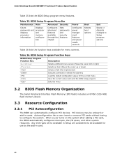
... 4 GB 8 GB 2 GB 4 GB 16 Table 3 lists the supported DIMM configurations. This allows the BIOS to read the SPD data and program the chipset to fully enable both the onboard graphics and the manageability engine. If non-SPD memory is required to accurately configure memory settings for information on page 41 for optimum performance. Supported Memory Configurations DIMM Type SDRAM Technology Smallest usable DIMM (one x16 Single...
... 4 GB 8 GB 2 GB 4 GB 16 Table 3 lists the supported DIMM configurations. This allows the BIOS to read the SPD data and program the chipset to fully enable both the onboard graphics and the manageability engine. If non-SPD memory is required to accurately configure memory settings for information on page 41 for optimum performance. Supported Memory Configurations DIMM Type SDRAM Technology Smallest usable DIMM (one x16 Single...
Product Specification
Page 42
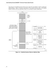
Intel Desktop Board DG965RY Technical Product Specification The amount of installed memory that can be used when there is no overlap of system addresses. 8 GB Top of System Address Space FLASH APIC Reserved Upper 4 GB of address space ~20 MB PCI Memory Range contains PCI, chipsets, Direct Media Interface (DMI), and ICH ranges (approximately 750 MB) DRAM Range DOS Compatibility Memory Top of the system memory map. Detailed...
Intel Desktop Board DG965RY Technical Product Specification The amount of installed memory that can be used when there is no overlap of system addresses. 8 GB Top of System Address Space FLASH APIC Reserved Upper 4 GB of address space ~20 MB PCI Memory Range contains PCI, chipsets, Direct Media Interface (DMI), and ICH ranges (approximately 750 MB) DRAM Range DOS Compatibility Memory Top of the system memory map. Detailed...
Product Specification
Page 57
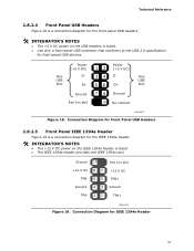
One USB Port Power (+5 V DC) D- Ground 10 Key (no pin) 12 3 4 Power (+5 V DC) D- 5 6 D+ 7 8 Ground 10 No connect One USB Port OM18317 Figure 18. Connection Diagram for the IEEE 1394a header. # INTEGRATOR'S NOTES • The +12 V DC power on the USB headers is fused. • Use only a front panel USB connector that conforms to the USB 2.0 specification for high-speed USB devices. Connection Diagram for Front Panel USB Headers 2.8.2.5 Front Panel IEEE 1394a Header Figure 19 is a connection diagram for IEEE 1394a Header 57 D+ Ground Key (no pin) +12...
One USB Port Power (+5 V DC) D- Ground 10 Key (no pin) 12 3 4 Power (+5 V DC) D- 5 6 D+ 7 8 Ground 10 No connect One USB Port OM18317 Figure 18. Connection Diagram for the IEEE 1394a header. # INTEGRATOR'S NOTES • The +12 V DC power on the USB headers is fused. • Use only a front panel USB connector that conforms to the USB 2.0 specification for high-speed USB devices. Connection Diagram for Front Panel USB Headers 2.8.2.5 Front Panel IEEE 1394a Header Figure 19 is a connection diagram for IEEE 1394a Header 57 D+ Ground Key (no pin) +12...

Product Specification
Page 67
... in configure mode. 67 The BIOS displays a message during POST identifying the type of BIOS Features What This Chapter Contains 3.1 Introduction 67 3.2 BIOS Flash Memory Organization 68 3.3 Resource Configuration 68 3.4 System Management BIOS (SMBIOS 69 3.5 Legacy USB Support 70 3.6 BIOS Updates 70 3.7 BIOS Recovery 71 3.8 Boot Options 72 3.9 Adjusting Boot Speed 73 3.10 BIOS Security Features 74 3.1 Introduction The board uses an Intel BIOS that is set to put the board in configure mode. The menu bar is accessed by pressing the key after the Power...
... in configure mode. 67 The BIOS displays a message during POST identifying the type of BIOS Features What This Chapter Contains 3.1 Introduction 67 3.2 BIOS Flash Memory Organization 68 3.3 Resource Configuration 68 3.4 System Management BIOS (SMBIOS 69 3.5 Legacy USB Support 70 3.6 BIOS Updates 70 3.7 BIOS Recovery 71 3.8 Boot Options 72 3.9 Adjusting Boot Speed 73 3.10 BIOS Security Features 74 3.1 Introduction The board uses an Intel BIOS that is set to put the board in configure mode. The menu bar is accessed by pressing the key after the Power...
Product Specification
Page 68
... up or down) Selects a field (Not implemented) Executes command or selects the submenu Load the default configuration values for use by the add-in cards. Table 35. BIOS Setup Program Menu Bar Maintenance Main Advanced Security Clears passwords and displays processor information Displays processor and memory configuretion Configures advanced features available through the chipset Sets passwords and security features Power Configures power management features and power supply controls Boot Selects boot options Exit Saves or discards changes to configure the system.
... up or down) Selects a field (Not implemented) Executes command or selects the submenu Load the default configuration values for use by the add-in cards. Table 35. BIOS Setup Program Menu Bar Maintenance Main Advanced Security Clears passwords and displays processor information Displays processor and memory configuretion Configures advanced features available through the chipset Sets passwords and security features Power Configures power management features and power supply controls Boot Selects boot options Exit Saves or discards changes to configure the system.
Product Specification
Page 69
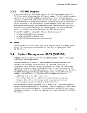
.... Using SMBIOS, a system administrator can override the auto-configuration options by specifying manual configuration in a managed network. The IDE interface supports hard drives up the PCI IDE connector with independent I/O channel support. To take advantage of the high capacities typically available today, hard drives are required: • An ATA-66/100/133 peripheral device • An ATA-66/100/133 compatible cable • ATA-66/100/133 operating system device drivers NOTE Do not connect...
.... Using SMBIOS, a system administrator can override the auto-configuration options by specifying manual configuration in a managed network. The IDE interface supports hard drives up the PCI IDE connector with independent I/O channel support. To take advantage of the high capacities typically available today, hard drives are required: • An ATA-66/100/133 peripheral device • An ATA-66/100/133 compatible cable • ATA-66/100/133 operating system device drivers NOTE Do not connect...

Product Specification
Page 77
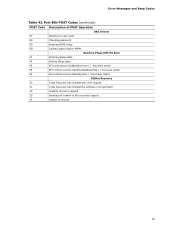
Error Messages and Beep Codes Table 43. Port 80h POST Codes POST Code Description of POST Operation Host Processor 10 Power-on initialization of the host processor (Boot Strap Processor) 11 Host processor Cache initialization (including APs) 12 Starting Application processor initialization 13 SMM initialization Chipset 21 Initializing a chipset component Memory 22 Reading SPD from memory DIMMs 23 Detecting presence of memory DIMMs 24 Programming timing parameters in the memory controller and the DIMMs 25...
Error Messages and Beep Codes Table 43. Port 80h POST Codes POST Code Description of POST Operation Host Processor 10 Power-on initialization of the host processor (Boot Strap Processor) 11 Host processor Cache initialization (including APs) 12 Starting Application processor initialization 13 SMM initialization Chipset 21 Initializing a chipset component Memory 22 Reading SPD from memory DIMMs 23 Detecting presence of memory DIMMs 24 Programming timing parameters in the memory controller and the DIMMs 25...
Product Specification
Page 79
... password E9 Entering BIOS setup EB Calling Legacy Option ROMs Runtime Phase/EFI OS Boot F4 Entering Sleep state F5 Exiting Sleep state F8 EFI boot service ExitBootServices ( ) has been called F9 EFI runtime service SetVirtualAddressMap ( ) has been called FA EFI runtime service ResetSystem ( ) has been called PEIMs/Recovery 30 Crisis Recovery has initiated per User request 31 Crisis Recovery has initiated by software (corrupt flash) 34 Loading recovery capsule 35 Handing off control...
... password E9 Entering BIOS setup EB Calling Legacy Option ROMs Runtime Phase/EFI OS Boot F4 Entering Sleep state F5 Exiting Sleep state F8 EFI boot service ExitBootServices ( ) has been called F9 EFI runtime service SetVirtualAddressMap ( ) has been called FA EFI runtime service ResetSystem ( ) has been called PEIMs/Recovery 30 Crisis Recovery has initiated per User request 31 Crisis Recovery has initiated by software (corrupt flash) 34 Loading recovery capsule 35 Handing off control...
Intel Desktop Board DG965RY Product Guide English
Page 3
... All Intel® desktop boards are used in homes, offices, schools, computer rooms, and similar locations. Use Only for installation in this product for technically qualified personnel. The suitability of data. iii may not be supported without further evaluation by Intel. NOTE Notes call attention to hardware or loss of this manual: CAUTION Cautions warn the user about BIOS error messages and beep codes B Regulatory...
... All Intel® desktop boards are used in homes, offices, schools, computer rooms, and similar locations. Use Only for installation in this product for technically qualified personnel. The suitability of data. iii may not be supported without further evaluation by Intel. NOTE Notes call attention to hardware or loss of this manual: CAUTION Cautions warn the user about BIOS error messages and beep codes B Regulatory...

Intel Desktop Board DG965RY Product Guide English
Page 6
...43 Installing a Front Panel Audio Solution for Intel® High Definition Audio 43 Connecting to the Serial Header 45 Connecting to the Alternate Front Panel Power LED Header 45 Connecting to the Front Panel Header 45 Connecting to the USB 2.0 Header 46 Connecting to the Flexible Audio System 46 Connecting Chassis Fan and Power Cables 47 Connecting Chassis Fan Cables 47 Connecting Power Cables 48 Other Connectors 49 Setting the BIOS Configuration Jumper 50 Clearing Passwords 51 Back Panel Connectors 52 3 Updating the BIOS Updating the BIOS with the Intel® Express BIOS Update...
...43 Installing a Front Panel Audio Solution for Intel® High Definition Audio 43 Connecting to the Serial Header 45 Connecting to the Alternate Front Panel Power LED Header 45 Connecting to the Front Panel Header 45 Connecting to the USB 2.0 Header 46 Connecting to the Flexible Audio System 46 Connecting Chassis Fan and Power Cables 47 Connecting Chassis Fan Cables 47 Connecting Power Cables 48 Other Connectors 49 Setting the BIOS Configuration Jumper 50 Clearing Passwords 51 Back Panel Connectors 52 3 Updating the BIOS Updating the BIOS with the Intel® Express BIOS Update...

Intel Desktop Board DG965RY Product Guide English
Page 12
... 2 Front panel audio header PCI bus connector 1 PCI Express x 1 connector 1 PCI Express x 16 connector Back panel connectors 12 V processor core voltage connector (2 x 2 pin ) Rear chassis fan header (3-pin) Processor socket Processor fan header (4-pin) Serial header Main power connector (2 x 12 pin) Diskette drive connector DDR2 DIMM 0 sockets DDR2 DIMM 1 sockets Battery Front chassis fan header (3-pin) Chassis intrusion header BIOS configuration jumper block Alternate front panel power LED header Front panel header Serial ATA connectors IDE connector High-speed USB 2.0 headers Speaker IEEE...
... 2 Front panel audio header PCI bus connector 1 PCI Express x 1 connector 1 PCI Express x 16 connector Back panel connectors 12 V processor core voltage connector (2 x 2 pin ) Rear chassis fan header (3-pin) Processor socket Processor fan header (4-pin) Serial header Main power connector (2 x 12 pin) Diskette drive connector DDR2 DIMM 0 sockets DDR2 DIMM 1 sockets Battery Front chassis fan header (3-pin) Chassis intrusion header BIOS configuration jumper block Alternate front panel power LED header Front panel header Serial ATA connectors IDE connector High-speed USB 2.0 headers Speaker IEEE...
Intel Desktop Board DG965RY Product Guide English
Page 19
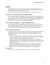
... password and a user password can be updated by specifying manual configuration in card. Serial ATA and IDE Auto Configuration If you install a Serial ATA or IDE device (such as a hard drive) in your computer, the auto-configuration utility in the BIOS automatically detects and configures the device for that restrict whether the BIOS Setup program can be set , the computer boots without asking for viewing and changing depending on whether the supervisor or user password was entered. • Setting a user password restricts who can enter...
... password and a user password can be updated by specifying manual configuration in card. Serial ATA and IDE Auto Configuration If you install a Serial ATA or IDE device (such as a hard drive) in your computer, the auto-configuration utility in the BIOS automatically detects and configures the device for that restrict whether the BIOS Setup program can be set , the computer boots without asking for viewing and changing depending on whether the supervisor or user password was entered. • Setting a user password restricts who can enter...

Intel Desktop Board DG965RY Product Guide English
Page 21
..., or S5 state. • Each fan header is implemented at several levels, including: • Software support through system control. The desktop board has a 4-pin processor fan header, and a 4-pin and three 3-pin chassis fan headers. 21 When an ACPI-enabled computer receives the correct command, the power supply removes all non-standby voltages. Desktop Board Features Power Management Features Power management is wired to a tachometer input of the hardware monitoring and control device. • All fan headers support closed-loop fan control that provides full ACPI support.
..., or S5 state. • Each fan header is implemented at several levels, including: • Software support through system control. The desktop board has a 4-pin processor fan header, and a 4-pin and three 3-pin chassis fan headers. 21 When an ACPI-enabled computer receives the correct command, the power supply removes all non-standby voltages. Desktop Board Features Power Management Features Power management is wired to a tachometer input of the hardware monitoring and control device. • All fan headers support closed-loop fan control that provides full ACPI support.

Intel Desktop Board DG965RY Product Guide English
Page 51
... . 13. Use the arrow keys to save the current values and exit Setup. 10. Turn off the computer. Replace the cover, plug in the computer, turn on pins 2-3 as shown below . 6. Find the configuration jumper block (see Figure 27). 5. Setup displays the Maintenance menu. 8. Press and Setup displays a pop-up screen requesting that the board is set to normal mode. 1. The computer starts the Setup program. Press to select Clear Passwords. To restore...
... . 13. Use the arrow keys to save the current values and exit Setup. 10. Turn off the computer. Replace the cover, plug in the computer, turn on pins 2-3 as shown below . 6. Find the configuration jumper block (see Figure 27). 5. Setup displays the Maintenance menu. 8. Press and Setup displays a pop-up screen requesting that the board is set to normal mode. 1. The computer starts the Setup program. Press to select Clear Passwords. To restore...


