Product Guide
Page 5
Contents 1 Desktop Board Features Desktop Board Components 11 Processor ...13 Main Memory...13 Intel® G45 Express Chipset 14 Intel G45 Graphics Subsystem 15 DVI-I Support 15 HDMI* Technology Support 15 Intel® Viiv™ Technology 15 Audio Subsystem 16 Legacy Input/Output (I/O) ...Fan Headers 23 LAN Wake Capabilities 23 Instantly Available PC Technology 23 +5 V Standby Power Indicator 24 Wake from USB 24 WAKE# Signal Wake-up Support 25 Wake from CIR 25 ENERGY STAR* Qualified 25 Speaker...25 Battery ...25 Real-Time Clock 25 2 Installing and Replacing Desktop Board...
Contents 1 Desktop Board Features Desktop Board Components 11 Processor ...13 Main Memory...13 Intel® G45 Express Chipset 14 Intel G45 Graphics Subsystem 15 DVI-I Support 15 HDMI* Technology Support 15 Intel® Viiv™ Technology 15 Audio Subsystem 16 Legacy Input/Output (I/O) ...Fan Headers 23 LAN Wake Capabilities 23 Instantly Available PC Technology 23 +5 V Standby Power Indicator 24 Wake from USB 24 WAKE# Signal Wake-up Support 25 Wake from CIR 25 ENERGY STAR* Qualified 25 Speaker...25 Battery ...25 Real-Time Clock 25 2 Installing and Replacing Desktop Board...
Product Guide
Page 6
Intel Desktop Board DG45FC Product Guide Installing the I/O Shield 29 Installing and Removing the Desktop Board 30 Installing and Removing a Processor 31 Installing a Processor 31 Installing a Processor Fan Heat Sink 34 Connecting the Processor Fan Heat Sink Cable 35 Removing the Processor 35 Installing and Removing Memory 36 ... Power Supply Cables 46 Chassis Fan Cables 46 Power Supply Cables 47 Setting the BIOS Configuration Jumper 48 Clearing Passwords 49 Replacing the Battery 50 3 Updating the BIOS 55 Updating the BIOS with the Intel® Express BIOS Update Utility ...
Intel Desktop Board DG45FC Product Guide Installing the I/O Shield 29 Installing and Removing the Desktop Board 30 Installing and Removing a Processor 31 Installing a Processor 31 Installing a Processor Fan Heat Sink 34 Connecting the Processor Fan Heat Sink Cable 35 Removing the Processor 35 Installing and Removing Memory 36 ... Power Supply Cables 46 Chassis Fan Cables 46 Power Supply Cables 47 Setting the BIOS Configuration Jumper 48 Clearing Passwords 49 Replacing the Battery 50 3 Updating the BIOS 55 Updating the BIOS with the Intel® Express BIOS Update Utility ...
Product Guide
Page 7
... Load Plate 34 12. Connecting the Processor Fan Heat Sink Cable 35 13. Removing the Battery 54 23. LAN Connector LEDs 18 vii Remove the Protective Socket Cover 32 9. Install the Processor 33 11. Use DDR2 DIMMs 37 15. Back Panel Audio Connectors 45 19. Desktop Board DG45FC Mounting Screw Hole Locations 30 6. Installing...
... Load Plate 34 12. Connecting the Processor Fan Heat Sink Cable 35 13. Removing the Battery 54 23. LAN Connector LEDs 18 vii Remove the Protective Socket Cover 32 9. Install the Processor 33 11. Use DDR2 DIMMs 37 15. Back Panel Audio Connectors 45 19. Desktop Board DG45FC Mounting Screw Hole Locations 30 6. Installing...
Product Guide
Page 10
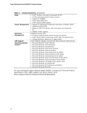
...Three fan sensing inputs used to monitor fan activity • Intel® Quiet System Technology (Intel® QST) fan speed control LAN Support • Voltage sensing to detect out of range values Intel®...Media Center Edition 2005 • Microsoft Windows XP Professional • Microsoft Windows XP Professional x64 Edition • Microsoft Windows XP Home For more information about Desktop Board DG45FC, including the Technical Product Specification (TPS), BIOS updates, and device drivers, go to http://support.intel.com/support/motherboards/desktop/. 10 Intel Desktop Board DG45FC...
...Three fan sensing inputs used to monitor fan activity • Intel® Quiet System Technology (Intel® QST) fan speed control LAN Support • Voltage sensing to detect out of range values Intel®...Media Center Edition 2005 • Microsoft Windows XP Professional • Microsoft Windows XP Professional x64 Edition • Microsoft Windows XP Home For more information about Desktop Board DG45FC, including the Technical Product Specification (TPS), BIOS updates, and device drivers, go to http://support.intel.com/support/motherboards/desktop/. 10 Intel Desktop Board DG45FC...
Product Guide
Page 21
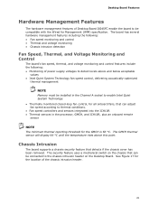
... hardware management features of Desktop Board DG45FC enable the board to be compatible with the Wired for the location of power supply voltages to detect levels above this point. The GMCH thermal sensor will display 66 °C until the temperature rises above and below acceptable values • Intel Quiet System Technology fan speed control, delivering acoustically...
... hardware management features of Desktop Board DG45FC enable the board to be compatible with the Wired for the location of power supply voltages to detect levels above this point. The GMCH thermal sensor will display 66 °C until the temperature rises above and below acceptable values • Intel Quiet System Technology fan speed control, delivering acoustically...
Product Guide
Page 22
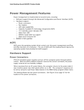
The Desktop Board has two power connectors. Intel Desktop Board DG45FC Product Guide Power Management Features Power management is implemented at several levels, including: • Software support through system control. When resuming from Consumer IR.... 22 See Figure 20 on or off the computer power through the Advanced Configuration and Power Interface (ACPI) • Hardware support: ⎯ Power connectors ⎯ Fan headers ⎯ LAN wake capabilities ⎯ Instantly Available PC technology (Suspend to RAM) ⎯ +5 V standby power indicator LED ⎯ Wake from USB ⎯...
The Desktop Board has two power connectors. Intel Desktop Board DG45FC Product Guide Power Management Features Power management is implemented at several levels, including: • Software support through system control. When resuming from Consumer IR.... 22 See Figure 20 on or off the computer power through the Advanced Configuration and Power Interface (ACPI) • Hardware support: ⎯ Power connectors ⎯ Fan headers ⎯ LAN wake capabilities ⎯ Instantly Available PC technology (Suspend to RAM) ⎯ +5 V standby power indicator LED ⎯ Wake from USB ⎯...
Product Guide
Page 23
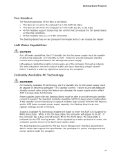
... based on the front panel, the sleep state is indicated by the LED turning amber. The Desktop Board has a 4-pin processor fan header and a 3-pin chassis fan header. LAN Wake Capabilities CAUTION For LAN wake capabilities, the 5 V standby line for the power supply must be off when the ... the power supply and/or effect ACPI S3 sleep state functionality. Desktop Board Features Fan Headers The function/operation of the fans is as follows: • The fans are on when the computer is in the ACPI S0 state. • The fans are off . The LAN subsystem monitors network traffic and upon detecting...
... based on the front panel, the sleep state is indicated by the LED turning amber. The Desktop Board has a 4-pin processor fan header and a 3-pin chassis fan header. LAN Wake Capabilities CAUTION For LAN wake capabilities, the 5 V standby line for the power supply must be off when the ... the power supply and/or effect ACPI S3 sleep state functionality. Desktop Board Features Fan Headers The function/operation of the fans is as follows: • The fans are on when the computer is in the ACPI S0 state. • The fans are off . The LAN subsystem monitors network traffic and upon detecting...
Product Guide
Page 27
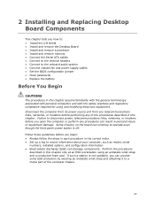
... This chapter tells you how to: • Install the I/O shield • Install and remove the Desktop Board • Install and remove a processor • Install and remove memory • Connect the Serial ATA cables • Connect to the internal headers • Connect ... networks, or modems before you open the computer or perform any of the computer chassis. 27 Failure to the onboard audio system • Connect chassis fan and power supply cables • Set the BIOS configuration jumper • Clear passwords • Replace the battery Before You Begin CAUTIONS The procedures in ...
... This chapter tells you how to: • Install the I/O shield • Install and remove the Desktop Board • Install and remove a processor • Install and remove memory • Connect the Serial ATA cables • Connect to the internal headers • Connect ... networks, or modems before you open the computer or perform any of the computer chassis. 27 Failure to the onboard audio system • Connect chassis fan and power supply cables • Set the BIOS configuration jumper • Clear passwords • Replace the battery Before You Begin CAUTIONS The procedures in ...
Product Guide
Page 34
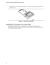
Figure 11. For instructions on the load plate (Figure 11, A), close and engage the socket lever (Figure 11, B). Close the Load Plate Installing a Processor Fan Heat Sink Desktop Board DG45FC has mounting holes for a processor fan heat sink. Intel Desktop Board DG45FC Product Guide 7. Pressing down on how to attach the processor fan heat sink to the Desktop Board, refer to the boxed processor manual. 34
Figure 11. For instructions on the load plate (Figure 11, A), close and engage the socket lever (Figure 11, B). Close the Load Plate Installing a Processor Fan Heat Sink Desktop Board DG45FC has mounting holes for a processor fan heat sink. Intel Desktop Board DG45FC Product Guide 7. Pressing down on how to attach the processor fan heat sink to the Desktop Board, refer to the boxed processor manual. 34
Product Guide
Page 35
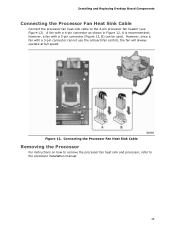
Installing and Replacing Desktop Board Components Connecting the Processor Fan Heat Sink Cable Connect the processor fan heat sink cable to the processor installation manual. 35 however, a fan with a 3-pin connector cannot use the onboard fan control, the fan will always operate at full speed. However, since a fan with a 3-pin connector (Figure 12, B) can be used. Figure 12. Connecting...
Installing and Replacing Desktop Board Components Connecting the Processor Fan Heat Sink Cable Connect the processor fan heat sink cable to the processor installation manual. 35 however, a fan with a 3-pin connector cannot use the onboard fan control, the fan will always operate at full speed. However, since a fan with a 3-pin connector (Figure 12, B) can be used. Figure 12. Connecting...
Product Guide
Page 46
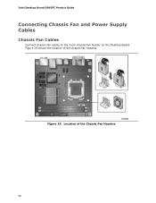
Intel Desktop Board DG45FC Product Guide Connecting Chassis Fan and Power Supply Cables Chassis Fan Cables Connect chassis fan cables to the 3-pin chassis fan header on the Desktop Board. Figure 19 shows the location of the Chassis Fan Headers 46 Location of the chassis fan headers. Figure 19.
Intel Desktop Board DG45FC Product Guide Connecting Chassis Fan and Power Supply Cables Chassis Fan Cables Connect chassis fan cables to the 3-pin chassis fan header on the Desktop Board. Figure 19 shows the location of the Chassis Fan Headers 46 Location of the chassis fan headers. Figure 19.


