Product Guide
Page 3
... applications or other hardware components 3 Updating the BIOS: instructions on how to update the BIOS A Error Messages and Indicators: information about BIOS error messages and beep codes B Regulatory Compliance: information about board layout, component installation, BIOS update, and regulatory requirements for technically qualified personnel. may not be supported without further evaluation by Intel. It is intended for Intel® Desktop Board DG41MJ. Preface This Product Guide gives information about safety standards, EMC...
... applications or other hardware components 3 Updating the BIOS: instructions on how to update the BIOS A Error Messages and Indicators: information about BIOS error messages and beep codes B Regulatory Compliance: information about board layout, component installation, BIOS update, and regulatory requirements for technically qualified personnel. may not be supported without further evaluation by Intel. It is intended for Intel® Desktop Board DG41MJ. Preface This Product Guide gives information about safety standards, EMC...

Product Guide
Page 5
...Desktop Board Components 11 Processor ...12 Main Memory...13 Intel® G41 Express Chipset 14 Graphics Support 14 Intel® GMA X4500 Graphics Controller 14 DVI Support 14 Audio Subsystem 15 Legacy Input/Output (I/O) Controller 15 LAN Subsystem 16 USB 2.0 Support 17 Serial ATA...17 Expandability...17 BIOS ...17 Serial ATA and IDE Auto Configuration 17 PCI* Auto Configuration 17 Security Passwords 18 Hardware Management Features 18 Hardware Monitoring and Fan Speed Control 18 Power Management Features 19 ACPI ...19 Hardware Support 19 Power Connectors 19 Fan Headers 20 LAN...
...Desktop Board Components 11 Processor ...12 Main Memory...13 Intel® G41 Express Chipset 14 Graphics Support 14 Intel® GMA X4500 Graphics Controller 14 DVI Support 14 Audio Subsystem 15 Legacy Input/Output (I/O) Controller 15 LAN Subsystem 16 USB 2.0 Support 17 Serial ATA...17 Expandability...17 BIOS ...17 Serial ATA and IDE Auto Configuration 17 PCI* Auto Configuration 17 Security Passwords 18 Hardware Management Features 18 Hardware Monitoring and Fan Speed Control 18 Power Management Features 19 ACPI ...19 Hardware Support 19 Power Connectors 19 Fan Headers 20 LAN...
Product Guide
Page 6
... SATA Drive 37 Connecting to the Internal Headers and Connectors 38 Front Panel Audio Header 39 Chassis Intrusion Header 39 USB 2.0 Headers 40 Serial Port Header 40 Alternate Front Panel Power LED Header 41 Front Panel Header 41 Connecting to the Back Panel Audio Connectors 42 Connecting Chassis Fan and Power Supply Cables 43 Connecting a Chassis Fan Cable 43 Connecting Supply Power Cables 44 Setting the BIOS Configuration Jumper 45 Clearing Passwords 46 Replacing the Battery 47 3 Updating the BIOS Updating the BIOS with the Intel® Express BIOS Update Utility 53 Updating...
... SATA Drive 37 Connecting to the Internal Headers and Connectors 38 Front Panel Audio Header 39 Chassis Intrusion Header 39 USB 2.0 Headers 40 Serial Port Header 40 Alternate Front Panel Power LED Header 41 Front Panel Header 41 Connecting to the Back Panel Audio Connectors 42 Connecting Chassis Fan and Power Supply Cables 43 Connecting a Chassis Fan Cable 43 Connecting Supply Power Cables 44 Setting the BIOS Configuration Jumper 45 Clearing Passwords 46 Replacing the Battery 47 3 Updating the BIOS Updating the BIOS with the Intel® Express BIOS Update Utility 53 Updating...
Product Guide
Page 7
...LAN Connector LEDs 16 5. Front Panel Header Signal Names 41 12. Connecting the Processor Fan Heat Sink Cable to -Slimline SATA Adapter Cable 37 18. Removing the Battery 51 Tables 1. BIOS Error Messages 57 15. LAN Connector LEDs 16 3. Chassis Intrusion Header Signal Names 39 8. Safety Standards 59 16. Internal Headers and Connectors 38 19. Connecting Power Supply Cables 44 22. Intel Desktop Board DG41MJ Mounting Screw Hole Locations 26 6. USB 2.0 Header Signal Names 40 9. Location of the BIOS Configuration Jumper Block 45 23. Jumper Settings for the BIOS Setup Program Modes...
...LAN Connector LEDs 16 5. Front Panel Header Signal Names 41 12. Connecting the Processor Fan Heat Sink Cable to -Slimline SATA Adapter Cable 37 18. Removing the Battery 51 Tables 1. BIOS Error Messages 57 15. LAN Connector LEDs 16 3. Chassis Intrusion Header Signal Names 39 8. Safety Standards 59 16. Internal Headers and Connectors 38 19. Connecting Power Supply Cables 44 22. Intel Desktop Board DG41MJ Mounting Screw Hole Locations 26 6. USB 2.0 Header Signal Names 40 9. Location of the BIOS Configuration Jumper Block 45 23. Jumper Settings for the BIOS Setup Program Modes...

Product Guide
Page 9
... One serial port header • PS/2* keyboard port on the back panel continued 9 1 Desktop Board Features This chapter briefly describes the features of : • Intel G41 Express Chipset Graphics and Memory Controller Hub (GMCH) with Intel® Graphics Media Accelerator X4500 (Intel® GMA X4500) • Intel® 82801GB I/O Controller Hub (ICH7) • Intel G41 Express Chipset Graphics and Memory Controller Hub (GMCH) • Integrated graphics (Intel® GMA X4500) with VGA and DVI-D outputs • One PCI* bus connector supporting PCI graphics cards • 5.1 channel...
... One serial port header • PS/2* keyboard port on the back panel continued 9 1 Desktop Board Features This chapter briefly describes the features of : • Intel G41 Express Chipset Graphics and Memory Controller Hub (GMCH) with Intel® Graphics Media Accelerator X4500 (Intel® GMA X4500) • Intel® 82801GB I/O Controller Hub (ICH7) • Intel G41 Express Chipset Graphics and Memory Controller Hub (GMCH) • Integrated graphics (Intel® GMA X4500) with VGA and DVI-D outputs • One PCI* bus connector supporting PCI graphics cards • 5.1 channel...
Product Guide
Page 10
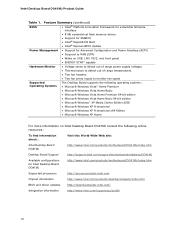
... site: Intel Desktop Board DG41MJ http://www.intel.com/products/motherboard/DG41MJ/index.htm Desktop Board Support http://support.intel.com/support/motherboards/desktop/DG41MJ Available configurations for Advanced Configuration and Power Interface (ACPI) • Suspend to RAM (STR) • Wake on USB, LAN, PS/2, and front panel • ENERGY STAR* capable Hardware Monitor • Voltage sense to detect out of range power supply voltages • Thermal sense to detect out of range temperatures • Two fan headers • Two fan sense inputs to monitor fan speed Supported...
... site: Intel Desktop Board DG41MJ http://www.intel.com/products/motherboard/DG41MJ/index.htm Desktop Board Support http://support.intel.com/support/motherboards/desktop/DG41MJ Available configurations for Advanced Configuration and Power Interface (ACPI) • Suspend to RAM (STR) • Wake on USB, LAN, PS/2, and front panel • ENERGY STAR* capable Hardware Monitor • Voltage sense to detect out of range power supply voltages • Thermal sense to detect out of range temperatures • Two fan headers • Two fan sense inputs to monitor fan speed Supported...

Product Guide
Page 12
...Product Guide Table 2. Intel Desktop Board DG41MJ Components Label A B C D E F G H I J K L M N O P Q R Description Front panel audio header Back panel connectors 12 V processor core voltage connector (2 x 2 pin) High-speed USB 2.0 headers (2) BIOS configuration jumper block Alternate front panel power LED header Processor socket Chassis fan header Processor fan header Serial port header Main power connector (2 x 12 pin) Battery Speaker DDR2 Channel B DIMM 0 socket DDR2 Channel A DIMM 0 socket Front panel header Serial ATA connectors (3) PCI bus connector Processor CAUTION Failure to use...
...Product Guide Table 2. Intel Desktop Board DG41MJ Components Label A B C D E F G H I J K L M N O P Q R Description Front panel audio header Back panel connectors 12 V processor core voltage connector (2 x 2 pin) High-speed USB 2.0 headers (2) BIOS configuration jumper block Alternate front panel power LED header Processor socket Chassis fan header Processor fan header Serial port header Main power connector (2 x 12 pin) Battery Speaker DDR2 Channel B DIMM 0 socket DDR2 Channel A DIMM 0 socket Front panel header Serial ATA connectors (3) PCI bus connector Processor CAUTION Failure to use...
Product Guide
Page 14
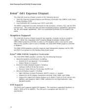
... be used or a PCI graphics add-in card is installed, the Intel GMA X4500 graphics controller is 2048 x 1536 at 75 Hz refresh rate (QXGA); The maximum supported resolution is disabled. Either the integrated Intel® Graphics Media Accelerator X4500 (Intel® GMA X4500) graphics controller is used . The GMA X4500 graphics controller supports dual independent displays via the VGA and DVI-D connectors on the Desktop Board back panel. The DVI port is a centralized controller for full High Definition video...
... be used or a PCI graphics add-in card is installed, the Intel GMA X4500 graphics controller is 2048 x 1536 at 75 Hz refresh rate (QXGA); The maximum supported resolution is disabled. Either the integrated Intel® Graphics Media Accelerator X4500 (Intel® GMA X4500) graphics controller is used . The GMA X4500 graphics controller supports dual independent displays via the VGA and DVI-D connectors on the Desktop Board back panel. The DVI port is a centralized controller for full High Definition video...
Product Guide
Page 17
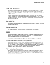
... BIOS Setup program after installing a Serial ATA or IDE device. Serial ATA The Desktop Board supports three Serial ATA channels (3.0 Gb/s) via ICH7. The BIOS can override the auto-configuration options by following the instructions on page 53 in card. USB 2.0 support requires both an operating system and drivers that add-in Chapter 3. BIOS The BIOS provides the Power-On Self-Test (POST), the BIOS Setup program, the PCI and IDE auto-configuration utilities, and the video BIOS. PCI* Auto Configuration If you install a Serial ATA or IDE device (such as a hard drive...
... BIOS Setup program after installing a Serial ATA or IDE device. Serial ATA The Desktop Board supports three Serial ATA channels (3.0 Gb/s) via ICH7. The BIOS can override the auto-configuration options by following the instructions on page 53 in card. USB 2.0 support requires both an operating system and drivers that add-in Chapter 3. BIOS The BIOS provides the Power-On Self-Test (POST), the BIOS Setup program, the PCI and IDE auto-configuration utilities, and the video BIOS. PCI* Auto Configuration If you install a Serial ATA or IDE device (such as a hard drive...
Product Guide
Page 18
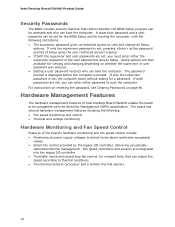
...8226; Thermally monitored closed-loop fan control, for onboard fans, that restrict whether the BIOS Setup program can be compatible with the following : • Fan speed monitoring and control • Thermal and voltage monitoring Hardware Monitoring and Fan Speed Control Features of the board's hardware monitoring and fan speed control include: • Monitoring of Intel Desktop Board DG41MJ enable the board to be accessed and who can enter either the supervisor password or the user password to access Setup. For instructions on resetting the password, see Clearing Passwords on...
...8226; Thermally monitored closed-loop fan control, for onboard fans, that restrict whether the BIOS Setup program can be compatible with the following : • Fan speed monitoring and control • Thermal and voltage monitoring Hardware Monitoring and Fan Speed Control Features of the board's hardware monitoring and fan speed control include: • Monitoring of Intel Desktop Board DG41MJ enable the board to be accessed and who can enter either the supervisor password or the user password to access Setup. For instructions on resetting the password, see Clearing Passwords on...
Product Guide
Page 19
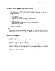
... provides full ACPI support. Desktop Board Features Power Management Features Power management is implemented at several levels, including: • Software support through system control. The Desktop Board has two power connectors. See Figure 21 on or off the computer power through the Advanced Configuration and Power Interface (ACPI) • Hardware support: ⎯ Power connectors ⎯ Fan headers ⎯ LAN wake capabilities ⎯ Instantly Available PC technology (Suspend to the power state it was in the BIOS Setup program's Boot menu.
... provides full ACPI support. Desktop Board Features Power Management Features Power management is implemented at several levels, including: • Software support through system control. The Desktop Board has two power connectors. See Figure 21 on or off the computer power through the Advanced Configuration and Power Interface (ACPI) • Hardware support: ⎯ Power connectors ⎯ Fan headers ⎯ LAN wake capabilities ⎯ Instantly Available PC technology (Suspend to the power state it was in the BIOS Setup program's Boot menu.
Product Guide
Page 20
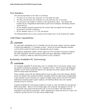
... to thermal conditions. • All fan headers have a +12 V DC connection. The Desktop Board has a 4-pin processor fan header and a 3-pin chassis fan header. Intel Desktop Board DG41MJ Product Guide Fan Headers The function/operation of the fans is as follows: • The fans are off . The chassis fan header has an independent tachometer input to the hardware monitoring and fan control device. • All fan headers support closed-loop fan control that powers up of the computer through a network. LAN wakeup capabilities enable remote wake-up the computer.
... to thermal conditions. • All fan headers have a +12 V DC connection. The Desktop Board has a 4-pin processor fan header and a 3-pin chassis fan header. Intel Desktop Board DG41MJ Product Guide Fan Headers The function/operation of the fans is as follows: • The fans are off . The chassis fan header has an independent tachometer input to the hardware monitoring and fan control device. • All fan headers support closed-loop fan control that powers up of the computer through a network. LAN wakeup capabilities enable remote wake-up the computer.

Product Guide
Page 21
... standby power indicator is still lit, disconnect the power cord before installing or removing any devices connected to do so could damage the board and any attached devices. Desktop Board Features The Desktop Board supports the PCI Bus Power Management Interface Specification. Location of the Standby Power Indicator For more information on the board even when the computer appears to be used to the Technical Product Specification at the memory module sockets and the PCI bus connector. Failure...
... standby power indicator is still lit, disconnect the power cord before installing or removing any devices connected to do so could damage the board and any attached devices. Desktop Board Features The Desktop Board supports the PCI Bus Power Management Interface Specification. Location of the Standby Power Indicator For more information on the board even when the computer appears to be used to the Technical Product Specification at the memory module sockets and the PCI bus connector. Failure...

Product Guide
Page 22
... US Environmental Protection Agency revised the ENERGY STAR requirements. This Desktop Board meets the ENERGY STAR Category B requirements. Wake From Serial Devices Serial port activity wakes the computer from USB. Battery A battery on the Desktop Board keeps the values in CMOS RAM and the clock current when the computer is turned off . Intel Desktop Board DG41MJ Product Guide Wake from USB Support NOTE Wake from USB requires the use of a USB peripheral that supports Wake from an ACPI S1 or S3 state.
... US Environmental Protection Agency revised the ENERGY STAR requirements. This Desktop Board meets the ENERGY STAR Category B requirements. Wake From Serial Devices Serial port activity wakes the computer from USB. Battery A battery on the Desktop Board keeps the values in CMOS RAM and the clock current when the computer is turned off . Intel Desktop Board DG41MJ Product Guide Wake from USB Support NOTE Wake from USB requires the use of a USB peripheral that supports Wake from an ACPI S1 or S3 state.

Product Guide
Page 23
... any of the computer chassis. 23 If such a station is off. 2 Installing and Replacing Desktop Board Components This chapter tells you how to: • Install the I/O shield • Install and remove the Desktop Board • Install and remove a processor • Install and remove memory • Use the Serial ATA cables • Connect to the internal headers and connectors • Connect to the audio system • Connect chassis fan and power supply cables • Set the BIOS configuration jumper • Clear passwords • Replace the battery Before You Begin CAUTION...
... any of the computer chassis. 23 If such a station is off. 2 Installing and Replacing Desktop Board Components This chapter tells you how to: • Install the I/O shield • Install and remove the Desktop Board • Install and remove a processor • Install and remove memory • Use the Serial ATA cables • Connect to the internal headers and connectors • Connect to the audio system • Connect chassis fan and power supply cables • Set the BIOS configuration jumper • Clear passwords • Replace the battery Before You Begin CAUTION...

Product Guide
Page 24
... instructions for the chassis are inconsistent with these instructions and the instructions provided by the chassis and module suppliers, you can ensure that the calculated total current loads of the power supply output circuits. Observe Safety and Regulatory Requirements Read and adhere to the instructions in the installation instructions. Intel Desktop Board DG41MJ Product Guide Installation Precautions When you to refer computer servicing to qualified technical personnel. Prevent Power Supply...
... instructions for the chassis are inconsistent with these instructions and the instructions provided by the chassis and module suppliers, you can ensure that the calculated total current loads of the power supply output circuits. Observe Safety and Regulatory Requirements Read and adhere to the instructions in the installation instructions. Intel Desktop Board DG41MJ Product Guide Installation Precautions When you to refer computer servicing to qualified technical personnel. Prevent Power Supply...

Product Guide
Page 43
Installing and Replacing Desktop Board Components Connecting Chassis Fan and Power Supply Cables Connecting a Chassis Fan Cable Connect your chassis fan cable to the 3-pin chassis fan header on the Desktop Board. Figure 20 shows the location of the Chassis Fan Header 43 Figure 20. Location of the chassis fan header.
Installing and Replacing Desktop Board Components Connecting Chassis Fan and Power Supply Cables Connecting a Chassis Fan Cable Connect your chassis fan cable to the 3-pin chassis fan header on the Desktop Board. Figure 20 shows the location of the Chassis Fan Header 43 Figure 20. Location of the chassis fan header.
Product Guide
Page 46
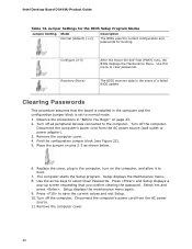
... BIOS Setup Program Modes Jumper Setting Mode Normal (default) (1-2) Description The BIOS uses the current configuration and passwords for booting. Use this menu to select Clear Passwords. Place the jumper on the computer, and allow it to save the current values and exit Setup. 10. Intel Desktop Board DG41MJ Product Guide Table 12. Configure (2-3) Recovery (None) After the Power-On Self-Test (POST) runs, the BIOS displays the Maintenance Menu. Clearing Passwords This procedure assumes that you confirm clearing the password. Turn off all peripheral devices connected...
... BIOS Setup Program Modes Jumper Setting Mode Normal (default) (1-2) Description The BIOS uses the current configuration and passwords for booting. Use this menu to select Clear Passwords. Place the jumper on the computer, and allow it to save the current values and exit Setup. 10. Intel Desktop Board DG41MJ Product Guide Table 12. Configure (2-3) Recovery (None) After the Power-On Self-Test (POST) runs, the BIOS displays the Maintenance Menu. Clearing Passwords This procedure assumes that you confirm clearing the password. Turn off all peripheral devices connected...
Product Guide
Page 53
.... Updating the BIOS with the Intel Express BIOS Update utility: 1. Download the file to your hard drive where it was saved. This step is included in the dialog boxes to a removable USB device. The BIOS file is required. Follow the instructions provided in an automated update utility that combines the functionality of the Intel® Flash Memory Update Utility and the ease of use of Windows-based installation wizards. Double-click the executable file from the location on your hard drive...
.... Updating the BIOS with the Intel Express BIOS Update utility: 1. Download the file to your hard drive where it was saved. This step is included in the dialog boxes to a removable USB device. The BIOS file is required. Follow the instructions provided in an automated update utility that combines the functionality of the Intel® Flash Memory Update Utility and the ease of use of Windows-based installation wizards. Double-click the executable file from the location on your hard drive...
Product Guide
Page 56
Intel Desktop Board DG41MJ Product Guide 1. Manually run the IFLASH.EXE file from a BIOS update failure, go to BIOS size and recovery requirements, a CD-R with the .BIO file in the root directory will interrupt the BIOS update; Configure the BIOS or use the F10 option during POST to boot to a bootable USB flash drive or other bootable USB media. 2. Uncompress the BIOS update file and copy the .BIO file, IFLASH.EXE, and .ITK file (optional) to the USB device. 3. Recovering the BIOS It is unlikely that anything will...
Intel Desktop Board DG41MJ Product Guide 1. Manually run the IFLASH.EXE file from a BIOS update failure, go to BIOS size and recovery requirements, a CD-R with the .BIO file in the root directory will interrupt the BIOS update; Configure the BIOS or use the F10 option during POST to boot to a bootable USB flash drive or other bootable USB media. 2. Uncompress the BIOS update file and copy the .BIO file, IFLASH.EXE, and .ITK file (optional) to the USB device. 3. Recovering the BIOS It is unlikely that anything will...


