
Product Specification
Page 5
... Summary 7 1.1.2 Board Layout 9 1.2 Online Support/Information 11 2 Technical Reference 2.1 Connectors, Headers, and Jumpers 13 2.1.1 Component-side Headers and Connectors 13 2.1.2 Component-side Jumpers 17 2.1.3 Back Panel Connectors 18 2.2 Mechanical Considerations 19 2.2.1 Form Factor 19 2.3 Electrical Considerations 20 2.3.1 Power Supply Considerations 20 2.4 Thermal Considerations 20 2.5 Reliability 21 2.6 ACPI Wake-up Devices and...
... Summary 7 1.1.2 Board Layout 9 1.2 Online Support/Information 11 2 Technical Reference 2.1 Connectors, Headers, and Jumpers 13 2.1.1 Component-side Headers and Connectors 13 2.1.2 Component-side Jumpers 17 2.1.3 Back Panel Connectors 18 2.2 Mechanical Considerations 19 2.2.1 Form Factor 19 2.3 Electrical Considerations 20 2.3.1 Power Supply Considerations 20 2.4 Thermal Considerations 20 2.5 Reliability 21 2.6 ACPI Wake-up Devices and...
Product Specification
Page 6
Intel Desktop Board DG41BI Technical Product Specification Tables 1. Board Components Shown in Figure 2 14 4. Chassis Fan Header 14 6. Front Panel USB1/USB2 Header 16 12. Main Power Connector 16 14. EMC Regulations 27 20. Product Certification Markings 30 vi ... S/PDIF Out Connector 15 9. Clear Password Jumper Settings 17 15. Feature Summary 7 2. Connectors and Headers Shown in Figure 1 10 3. Front Panel Audio Header 15 8. Processor Core Power Connector 16 13. Processor Fan Header 15 7. Recommended Power Supply Current Values 20 16. Safety Standards 23 19...
Intel Desktop Board DG41BI Technical Product Specification Tables 1. Board Components Shown in Figure 2 14 4. Chassis Fan Header 14 6. Front Panel USB1/USB2 Header 16 12. Main Power Connector 16 14. EMC Regulations 27 20. Product Certification Markings 30 vi ... S/PDIF Out Connector 15 9. Clear Password Jumper Settings 17 15. Feature Summary 7 2. Connectors and Headers Shown in Figure 1 10 3. Front Panel Audio Header 15 8. Processor Core Power Connector 16 13. Processor Fan Header 15 7. Recommended Power Supply Current Values 20 16. Safety Standards 23 19...
Product Specification
Page 7
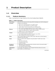
... to 4 GB of system memory Intel® G41 Express Chipset, consisting of the Intel Desktop Board DG41BI. 1 Product Description 1.1 Overview 1.1.1 Feature Summary Table 1 summarizes the major features of : • Intel® 82G41 Graphics and Memory Controller Hub (GMCH) • Intel® 82801GB I/O Controller Hub (ICH7) Intel® Graphics Media Accelerator X4500 (Intel® GMA X4500) onboard graphics...
... to 4 GB of system memory Intel® G41 Express Chipset, consisting of the Intel Desktop Board DG41BI. 1 Product Description 1.1 Overview 1.1.1 Feature Summary Table 1 summarizes the major features of : • Intel® 82G41 Graphics and Memory Controller Hub (GMCH) • Intel® 82801GB I/O Controller Hub (ICH7) Intel® Graphics Media Accelerator X4500 (Intel® GMA X4500) onboard graphics...
Product Specification
Page 8
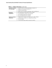
... Capabilities • Support for PCI* Local Bus Specification, Revision 2.3 • Support for PCI Express* Revision 1.1 • Suspend to RAM support • Wake on PCI, front panel, PCI Express, LAN, and USB ports • One PCI Express x16 bus add-in card connector • Two PCI Express x1 add-in card connectors... voltages • Thermal sense to detect out of range thermal values • Two fan headers • Two fan sense inputs used to monitor fan activity 8 Intel Desktop Board DG41BI Technical Product Specification Table 1.
... Capabilities • Support for PCI* Local Bus Specification, Revision 2.3 • Support for PCI Express* Revision 1.1 • Suspend to RAM support • Wake on PCI, front panel, PCI Express, LAN, and USB ports • One PCI Express x16 bus add-in card connector • Two PCI Express x1 add-in card connectors... voltages • Thermal sense to detect out of range thermal values • Two fan headers • Two fan sense inputs used to monitor fan activity 8 Intel Desktop Board DG41BI Technical Product Specification Table 1.
Product Specification
Page 14
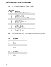
...Headers Shown in Figure 2 Item/callout in Figure 2 Description A Conventional PCI bus add-in Figure 2. Intel Desktop Board DG41BI Technical Product Specification Table 3 lists the connectors and headers identified in card connector B PCI Express x1 connector...fan header G Processor fan header H Main power connector (2 X 12) I Front panel header J Serial ATA connectors K Front panel USB header L Front panel USB header M Wireless LAN LED connector N S/PDIF connector O Front panel audio header Table 4 though Table 13 list the signal names for the component-side ...
...Headers Shown in Figure 2 Item/callout in Figure 2 Description A Conventional PCI bus add-in Figure 2. Intel Desktop Board DG41BI Technical Product Specification Table 3 lists the connectors and headers identified in card connector B PCI Express x1 connector...fan header G Processor fan header H Main power connector (2 X 12) I Front panel header J Serial ATA connectors K Front panel USB header L Front panel USB header M Wireless LAN LED connector N S/PDIF connector O Front panel audio header Table 4 though Table 13 list the signal names for the component-side ...
Product Specification
Page 15
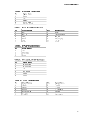
...2 SPDIF_O2_L 3 Ground Table 9. Wireless LAN LED Connector Pin Signal Name 1 No connector 2 No connector 3 +5V 4 LED_WLAN# 5 Ground 6 Ground Table 10. Front Panel Header Pin Signal Name Pin 1 HDLED+ 2 3 HDLED- 4 5 Ground 6 7 FP_SYS_RST# 8 9 FPA_DET# 10 Signal Name AGND F_AUDIO_DET# MIC_JD KEY (no pin)... Fan Header Pin Signal Name 1 Ground 2 +12 V 3 CFAN_D 4 CPUFAN_PWM_C Table 7. Technical Reference Table 6. Front Panel Audio Header Pin Signal Name Pin 1 MIC2_L 2 3 MIC2_R 4 5 LIN2_R 6 7 AGND 8 9 LIN2_L 10 Table 8.
...2 SPDIF_O2_L 3 Ground Table 9. Wireless LAN LED Connector Pin Signal Name 1 No connector 2 No connector 3 +5V 4 LED_WLAN# 5 Ground 6 Ground Table 10. Front Panel Header Pin Signal Name Pin 1 HDLED+ 2 3 HDLED- 4 5 Ground 6 7 FP_SYS_RST# 8 9 FPA_DET# 10 Signal Name AGND F_AUDIO_DET# MIC_JD KEY (no pin)... Fan Header Pin Signal Name 1 Ground 2 +12 V 3 CFAN_D 4 CPUFAN_PWM_C Table 7. Technical Reference Table 6. Front Panel Audio Header Pin Signal Name Pin 1 MIC2_L 2 3 MIC2_R 4 5 LIN2_R 6 7 AGND 8 9 LIN2_L 10 Table 8.
Product Specification
Page 16
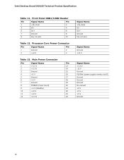
... (Power Good) 20 9 +5 V (Standby) 21 10 +12 V 22 11 +12 V 23 12 +3.3 V 24 Signal Name +5V_Dual D2D2+ Ground Key (no pin) 10 Table 12. Front Panel USB1/USB2 Header Pin Signal Name Pin 1 +5V_Dual 2 3 D1- 4 5 D1+ 6 7 Ground 8 9 Key (no pin) Signal Name Ground +12 V Signal Name +3.3 V -12 V Ground PS-ON# (...power supply remote on/off) Ground Ground Ground No connect +5 V +5 V +5 V Ground 16 Processor Core Power Connector Pin Signal Name Pin 1 Ground 2 3 +12 V 4 Table 13. Intel Desktop Board DG41BI Technical Product Specification Table 11.
... (Power Good) 20 9 +5 V (Standby) 21 10 +12 V 22 11 +12 V 23 12 +3.3 V 24 Signal Name +5V_Dual D2D2+ Ground Key (no pin) 10 Table 12. Front Panel USB1/USB2 Header Pin Signal Name Pin 1 +5V_Dual 2 3 D1- 4 5 D1+ 6 7 Ground 8 9 Key (no pin) Signal Name Ground +12 V Signal Name +3.3 V -12 V Ground PS-ON# (...power supply remote on/off) Ground Ground Ground No connect +5 V +5 V +5 V Ground 16 Processor Core Power Connector Pin Signal Name Pin 1 Ground 2 3 +12 V 4 Table 13. Intel Desktop Board DG41BI Technical Product Specification Table 11.
Product Specification
Page 18
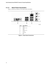
Intel Desktop Board DG41BI Technical Product Specification 2.1.3 Back Panel Connectors Figure 4 shows the locations of the back panel connectors. Back Panel Connectors 18 Item A B C D E F G Description VGA USB 2.0 (2) LAN USB 2.0 (2) Line in Line out Mic Figure 4.
Intel Desktop Board DG41BI Technical Product Specification 2.1.3 Back Panel Connectors Figure 4 shows the locations of the back panel connectors. Back Panel Connectors 18 Item A B C D E F G Description VGA USB 2.0 (2) LAN USB 2.0 (2) Line in Line out Mic Figure 4.


