

Product Specification
Page 6
... Legacy USB Support 61 3.6 BIOS Updates 62 3.6.1 Language Support 62 3.6.2 Custom Splash Screen 63 3.7 BIOS Recovery 63 3.8 Boot Options 64 3.8.1 Optical Drive Boot 64 3.8.2 Network Boot 64 3.8.3 Booting Without Attached Devices 64 3.8.4 Changing the Default Boot Device During POST 64 3.9 Adjusting Boot Speed 65 3.9.1 Peripheral Selection and Configuration 65 3.9.2 BIOS Boot Optimizations 65 3.10 BIOS Security Features 66 4 Error Messages and Beep Codes 4.1 Speaker 67 4.2 BIOS Beep Codes 67 4.3 Front-panel Power LED Blink Codes 68 4.4 BIOS Error Messages 68 4.5 Port 80h POST...
... Legacy USB Support 61 3.6 BIOS Updates 62 3.6.1 Language Support 62 3.6.2 Custom Splash Screen 63 3.7 BIOS Recovery 63 3.8 Boot Options 64 3.8.1 Optical Drive Boot 64 3.8.2 Network Boot 64 3.8.3 Booting Without Attached Devices 64 3.8.4 Changing the Default Boot Device During POST 64 3.9 Adjusting Boot Speed 65 3.9.1 Peripheral Selection and Configuration 65 3.9.2 BIOS Boot Optimizations 65 3.10 BIOS Security Features 66 4 Error Messages and Beep Codes 4.1 Speaker 67 4.2 BIOS Beep Codes 67 4.3 Front-panel Power LED Blink Codes 68 4.4 BIOS Error Messages 68 4.5 Port 80h POST...
Product Specification
Page 7
...a One-Color Power LED 48 23. BIOS Setup Configuration Jumper Settings 51 26. Component-side Connectors and Headers Shown in Figure 1 12 3. Front Chassis Fan Header 44 15. Auxiliary Front Panel Power/Sleep LED Header 45 19. Back Panel Audio Connectors 24 5. LAN Connector LED States 26 6. Main Power Connector 46 21. LAN Connector LED Locations 26 6. Back Panel Connectors 41 10. Contents Figures 1. Serial Port Header 44 14. Front Panel Audio Header for AC '97 Audio 45 18. Location of the Standby Power Indicator LED 35 8. Processor Core Power Connector 46 20...
...a One-Color Power LED 48 23. BIOS Setup Configuration Jumper Settings 51 26. Component-side Connectors and Headers Shown in Figure 1 12 3. Front Chassis Fan Header 44 15. Auxiliary Front Panel Power/Sleep LED Header 45 19. Back Panel Audio Connectors 24 5. LAN Connector LED States 26 6. Main Power Connector 46 21. LAN Connector LED Locations 26 6. Back Panel Connectors 41 10. Contents Figures 1. Serial Port Header 44 14. Front Panel Audio Header for AC '97 Audio 45 18. Location of the Standby Power Indicator LED 35 8. Processor Core Power Connector 46 20...

Product Specification
Page 9
... Serial ATA (SATA) interfaces • One PS/2 keyboard/mouse port on back panel • One serial port header (may require specialized chassis or cable for use) • Parallel port on back panel LAN Support BIOS 10/100/1000 Mbits/sec LAN subsystem using the Realtek* ALC888VC audio codec Legacy I/O Control Peripheral Interfaces Winbond W83627DHG-P based Legacy I/O controller for hardware management, serial, parallel, and PS/2* ports • Eight USB 2.0 ports: four back panel connectors and two front panel headers for support of Intel® Desktop Board DG41AN...
... Serial ATA (SATA) interfaces • One PS/2 keyboard/mouse port on back panel • One serial port header (may require specialized chassis or cable for use) • Parallel port on back panel LAN Support BIOS 10/100/1000 Mbits/sec LAN subsystem using the Realtek* ALC888VC audio codec Legacy I/O Control Peripheral Interfaces Winbond W83627DHG-P based Legacy I/O controller for hardware management, serial, parallel, and PS/2* ports • Eight USB 2.0 ports: four back panel connectors and two front panel headers for support of Intel® Desktop Board DG41AN...

Product Specification
Page 14
... ... Intel Desktop Board DG41AN Technical Product Specification 1.2 Legacy Considerations This board differs from other Intel® Desktop Board products, with a maximum wattage of supported processors. Use of the board. See the Intel web site listed below for the Intel Desktop Board D425KT and Intel Desktop Board D425KTW Supported processors Chipset information BIOS and driver updates Tested memory Integration information Visit this World Wide Web site: http://www.intel.com/products/motherboard/index.htm http://www.intel.com/p/en_US/support?iid=hdr+support http://ark.intel...
... ... Intel Desktop Board DG41AN Technical Product Specification 1.2 Legacy Considerations This board differs from other Intel® Desktop Board products, with a maximum wattage of supported processors. Use of the board. See the Intel web site listed below for the Intel Desktop Board D425KT and Intel Desktop Board D425KTW Supported processors Chipset information BIOS and driver updates Tested memory Integration information Visit this World Wide Web site: http://www.intel.com/products/motherboard/index.htm http://www.intel.com/p/en_US/support?iid=hdr+support http://ark.intel...

Product Specification
Page 22
... interface compatible with an equivalent one. Figure 1 on the component side of three years. When the computer is located on page 11 shows the location of the battery. 1.8 Legacy I/O Controller The I /O controller. 1.8.1 Serial Port Interface The serial port header is not plugged into CMOS RAM at speeds up to 115.2 kbits/s with 3.3 VSB applied. Intel Desktop Board DG41AN Technical Product Specification 1.7 Real-Time Clock Subsystem A coin-cell battery (CR2032) powers the real-time clock and CMOS memory.
... interface compatible with an equivalent one. Figure 1 on the component side of three years. When the computer is located on page 11 shows the location of the battery. 1.8 Legacy I/O Controller The I /O controller. 1.8.1 Serial Port Interface The serial port header is not plugged into CMOS RAM at speeds up to 115.2 kbits/s with 3.3 VSB applied. Intel Desktop Board DG41AN Technical Product Specification 1.7 Real-Time Clock Subsystem A coin-cell battery (CR2032) powers the real-time clock and CMOS memory.

Product Specification
Page 25
.../1000 Mbits/s Ethernet LAN connectivity • RJ-45 LAN connector with integrated status LEDs Additional features of the LAN subsystem include: • CSMA/CD protocol engine • LAN connect interface between ICH7 and the LAN controller • Conventional PCI bus power management ⎯ ACPI technology support ⎯ LAN wake capabilities • LAN subsystem software For information about Obtaining LAN software and drivers Refer to http://downloadcenter.intel.com 1.10.1 LAN Subsystem Software LAN software and drivers are available from...
.../1000 Mbits/s Ethernet LAN connectivity • RJ-45 LAN connector with integrated status LEDs Additional features of the LAN subsystem include: • CSMA/CD protocol engine • LAN connect interface between ICH7 and the LAN controller • Conventional PCI bus power management ⎯ ACPI technology support ⎯ LAN wake capabilities • LAN subsystem software For information about Obtaining LAN software and drivers Refer to http://downloadcenter.intel.com 1.10.1 LAN Subsystem Software LAN software and drivers are available from...
Product Specification
Page 59
... the BIOS Setup configuration jumper is set to put the board in the Serial Peripheral Interface Flash Memory (SPI Flash) and can be updated using a disk-based program. The initial production BIOSs are identified as ANG4110H.86A. Maintenance Main Advanced Security Power Boot Exit NOTE The maintenance menu is displayed only when the board is stored in configure mode. 59 The BIOS displays a message during POST identifying the type of BIOS Features 3.1 Introduction The board uses an Intel BIOS that...
... the BIOS Setup configuration jumper is set to put the board in the Serial Peripheral Interface Flash Memory (SPI Flash) and can be updated using a disk-based program. The initial production BIOSs are identified as ANG4110H.86A. Maintenance Main Advanced Security Power Boot Exit NOTE The maintenance menu is displayed only when the board is stored in configure mode. 59 The BIOS displays a message during POST identifying the type of BIOS Features 3.1 Introduction The board uses an Intel BIOS that...

Product Specification
Page 60
.... Intel Desktop Board DG41AN Technical Product Specification Table 31 lists the BIOS Setup program menu features. PCI devices may be available for use by the add-in Setup are considered to configure the system. Table 31. BIOS Setup Program Menu Bar Maintenance Main Advanced Security Clears passwords and displays processor information Displays processor and memory configuration Configures advanced features available through the chipset Sets passwords and security features Power Boot Configures power management features and power supply controls Selects boot options Exit...
.... Intel Desktop Board DG41AN Technical Product Specification Table 31 lists the BIOS Setup program menu features. PCI devices may be available for use by the add-in Setup are considered to configure the system. Table 31. BIOS Setup Program Menu Bar Maintenance Main Advanced Security Clears passwords and displays processor information Displays processor and memory configuration Configures advanced features available through the chipset Sets passwords and security features Power Boot Configures power management features and power supply controls Selects boot options Exit...

Product Specification
Page 61
... peripherals, serial numbers, and asset tags • Resource data, such as memory size, cache size, and processor speed • Dynamic data, such as event detection and error logging Non-Plug and Play operating systems require an additional interface for system components. Legacy USB support is enabled by using Intel® Integrator Toolkit. 61 Legacy USB support operates as third-party management software to use a USB keyboard to use SMBIOS. Legacy USB support is used to configure the...
... peripherals, serial numbers, and asset tags • Resource data, such as memory size, cache size, and processor speed • Dynamic data, such as event detection and error logging Non-Plug and Play operating systems require an additional interface for system components. Legacy USB support is enabled by using Intel® Integrator Toolkit. 61 Legacy USB support operates as third-party management software to use a USB keyboard to use SMBIOS. Legacy USB support is used to configure the...
Product Specification
Page 69
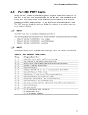
... unrecoverable processor error. Displaying the POST codes requires a PCI bus add-in PCI bus connector 1. The POST card can decode the port and display the contents on a medium such as a seven-segment display. Memory/Chipset: 2F is no memory detected or no useful memory detected. 30 - 3F Recovery: 3F indicated recovery failure. 40 - 4F Reserved for future use (new output console codes). FF E0 - NOTE The POST card must be used by the BIOS. • Table 39 lists the Port 80h POST code...
... unrecoverable processor error. Displaying the POST codes requires a PCI bus add-in PCI bus connector 1. The POST card can decode the port and display the contents on a medium such as a seven-segment display. Memory/Chipset: 2F is no memory detected or no useful memory detected. 30 - 3F Recovery: 3F indicated recovery failure. 40 - 4F Reserved for future use (new output console codes). FF E0 - NOTE The POST card must be used by the BIOS. • Table 39 lists the Port 80h POST code...
Product Specification
Page 71
... Resetting removable media B9 Disabling removable media BA Detecting presence of a removable media (IDE, CD-ROM detection, etc.) BC Enabling/configuring a removable media BDS Dy Trying boot selection y (y=0 to 15) PEI Core E0 Started dispatching PEIMs (emitted on first report of EFI_SW_PC_INIT_BEGIN EFI_SW_PEI_PC_HANDOFF_TO_NEXT) E2 Permanent memory found E1, E3 Reserved for PEI/PEIMs DXE Core E4 Entered DXE phase E5 Started dispatching drivers E6 Started connecting drivers continued 71 Error Messages and Beep Codes...
... Resetting removable media B9 Disabling removable media BA Detecting presence of a removable media (IDE, CD-ROM detection, etc.) BC Enabling/configuring a removable media BDS Dy Trying boot selection y (y=0 to 15) PEI Core E0 Started dispatching PEIMs (emitted on first report of EFI_SW_PC_INIT_BEGIN EFI_SW_PEI_PC_HANDOFF_TO_NEXT) E2 Permanent memory found E1, E3 Reserved for PEI/PEIMs DXE Core E4 Entered DXE phase E5 Started dispatching drivers E6 Started connecting drivers continued 71 Error Messages and Beep Codes...

Product Specification
Page 72
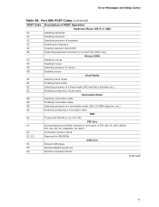
Intel Desktop Board DG41AN Technical Product Specification Table 40. Port 80h POST Codes (continued) POST Code Description of POST Operation DXE Drivers E7 Waiting for user input E8 Checking password E9 Entering BIOS setup EB Calling Legacy Option ROMs Runtime Phase/EFI OS Boot F4 Entering Sleep state F5 Exiting Sleep state F8 EFI boot service ExitBootServices ( ) has been called F9 EFI runtime service SetVirtualAddressMap ( ) has been called FA EFI runtime service ResetSystem ( ) has been called PEIMs/Recovery 30 Crisis...
Intel Desktop Board DG41AN Technical Product Specification Table 40. Port 80h POST Codes (continued) POST Code Description of POST Operation DXE Drivers E7 Waiting for user input E8 Checking password E9 Entering BIOS setup EB Calling Legacy Option ROMs Runtime Phase/EFI OS Boot F4 Entering Sleep state F5 Exiting Sleep state F8 EFI boot service ExitBootServices ( ) has been called F9 EFI runtime service SetVirtualAddressMap ( ) has been called FA EFI runtime service ResetSystem ( ) has been called PEIMs/Recovery 30 Crisis...
Product Specification
Page 73
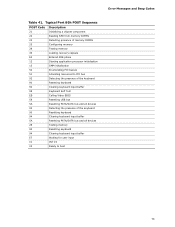
Error Messages and Beep Codes Table 41. Typical Port 80h POST Sequence POST Code Description 21 Initializing a chipset component 22 Reading SPD from memory DIMMs 23 Detecting presence of memory DIMMs 25 Configuring memory 28 Testing memory 34 Loading recovery capsule E4 Entered DXE phase 12 Starting application processor initialization 13 SMM initialization 50 Enumerating PCI busses 51 Allocating resourced to PCI bus 92 Detecting the presence of the keyboard 90 Resetting keyboard 94 Clearing keyboard input...
Error Messages and Beep Codes Table 41. Typical Port 80h POST Sequence POST Code Description 21 Initializing a chipset component 22 Reading SPD from memory DIMMs 23 Detecting presence of memory DIMMs 25 Configuring memory 28 Testing memory 34 Loading recovery capsule E4 Entered DXE phase 12 Starting application processor initialization 13 SMM initialization 50 Enumerating PCI busses 51 Allocating resourced to PCI bus 92 Detecting the presence of the keyboard 90 Resetting keyboard 94 Clearing keyboard input...

Intel Desktop Board DG41AN Product Guide English
Page 3
... Replacing Desktop Board Components: instructions on how to install the Desktop Board and other environments, such as Information Technology Equipment (I.T.E.) for use in personal computers (PC) for installation in this product for other PC or embedded non-PC applications or other hardware components 3 Updating the BIOS: instructions on how to update the BIOS A Error Messages and Indicators: information about BIOS error messages and beep codes B Regulatory Compliance: information about board layout, component installation, BIOS update...
... Replacing Desktop Board Components: instructions on how to install the Desktop Board and other environments, such as Information Technology Equipment (I.T.E.) for use in personal computers (PC) for installation in this product for other PC or embedded non-PC applications or other hardware components 3 Updating the BIOS: instructions on how to update the BIOS A Error Messages and Indicators: information about BIOS error messages and beep codes B Regulatory Compliance: information about board layout, component installation, BIOS update...

Intel Desktop Board DG41AN Product Guide English
Page 6
... SATA Drive 37 Connecting to the Internal Headers and Connectors 38 Front Panel Audio Header 39 Chassis Intrusion Header 39 Serial Port Header 40 USB 2.0 Headers 40 Alternate Front Panel Power LED Header 41 Front Panel Header 41 Connecting to the Back Panel Audio Connectors 42 Connecting Chassis Fan and Power Supply Cables 43 Connecting a Chassis Fan Cable 43 Connecting Power Supply Cables 44 Setting the BIOS Configuration Jumper 45 Clearing Passwords 46 Replacing the Battery 47 3 Updating the BIOS Updating the BIOS with the Intel® Express BIOS Update Utility 52 Updating...
... SATA Drive 37 Connecting to the Internal Headers and Connectors 38 Front Panel Audio Header 39 Chassis Intrusion Header 39 Serial Port Header 40 USB 2.0 Headers 40 Alternate Front Panel Power LED Header 41 Front Panel Header 41 Connecting to the Back Panel Audio Connectors 42 Connecting Chassis Fan and Power Supply Cables 43 Connecting a Chassis Fan Cable 43 Connecting Power Supply Cables 44 Setting the BIOS Configuration Jumper 45 Clearing Passwords 46 Replacing the Battery 47 3 Updating the BIOS Updating the BIOS with the Intel® Express BIOS Update Utility 52 Updating...
Intel Desktop Board DG41AN Product Guide English
Page 7
... Support 16 5. USB 2.0 Header Signal Names 40 11. BIOS Beep Codes 56 15. Location of the Chassis Fan Header 43 21. Lift the Load Plate 29 8. Chassis Intrusion Header Signal Names 39 9. Front Panel Header Signal Names 41 13. BIOS Error Messages 57 vii Close the Load Plate 31 12. Installing a DIMM 35 16. Internal Headers and Connectors 38 19. Location of the BIOS Configuration Jumper Block 45 23. Install the Processor 30 11. Using the Standard SATA Cable 36 17. Intel Desktop Board DG41AN...
... Support 16 5. USB 2.0 Header Signal Names 40 11. BIOS Beep Codes 56 15. Location of the Chassis Fan Header 43 21. Lift the Load Plate 29 8. Chassis Intrusion Header Signal Names 39 9. Front Panel Header Signal Names 41 13. BIOS Error Messages 57 vii Close the Load Plate 31 12. Installing a DIMM 35 16. Internal Headers and Connectors 38 19. Location of the BIOS Configuration Jumper Block 45 23. Install the Processor 30 11. Using the Standard SATA Cable 36 17. Intel Desktop Board DG41AN...

Intel Desktop Board DG41AN Product Guide English
Page 9
... PCI* bus connector supporting PCI graphics cards • 5.1 channel in single-stream mode or 4 + 2 channel in multistreaming mode, featuring: ― Realtek* ALC888VC audio codec ― Support for Intel® High Definition Audio (Intel® HD Audio) and AC '97 Audio LAN Support Expansion Capabilities Realtek 8111E Gigabit Ethernet Controller for operation at 10/100/1000 Mb/s One PCI bus connector Peripheral Interfaces • Up to eight USB 2.0 ports: ― Four ports routed to the back panel ― Four ports routed...
... PCI* bus connector supporting PCI graphics cards • 5.1 channel in single-stream mode or 4 + 2 channel in multistreaming mode, featuring: ― Realtek* ALC888VC audio codec ― Support for Intel® High Definition Audio (Intel® HD Audio) and AC '97 Audio LAN Support Expansion Capabilities Realtek 8111E Gigabit Ethernet Controller for operation at 10/100/1000 Mb/s One PCI bus connector Peripheral Interfaces • Up to eight USB 2.0 ports: ― Four ports routed to the back panel ― Four ports routed...

Intel Desktop Board DG41AN Product Guide English
Page 18
USB 2.0 ports are backward compatible with USB 1.1 devices. BIOS The BIOS provides the Power-On Self-Test (POST), the BIOS Setup program, the PCI and Serial ATA auto-configuration utilities, and the video BIOS. The BIOS can override the auto-configuration options by following the instructions on page 52 in card. 18 You do not need to run the BIOS Setup program after you install a PCI add-in Chapter 3. USB 2.0 support requires both an operating system and drivers that add-in the...
USB 2.0 ports are backward compatible with USB 1.1 devices. BIOS The BIOS provides the Power-On Self-Test (POST), the BIOS Setup program, the PCI and Serial ATA auto-configuration utilities, and the video BIOS. The BIOS can override the auto-configuration options by following the instructions on page 52 in card. 18 You do not need to run the BIOS Setup program after you install a PCI add-in Chapter 3. USB 2.0 support requires both an operating system and drivers that add-in the...

Intel Desktop Board DG41AN Product Guide English
Page 21
...; All fan headers have a +12 V DC connection. LAN wakeup capabilities enable remote wake-up of delivering adequate +5 V standby current. Power supplies used with this feature can adjust the fan speed according to provide adequate standby current when using this feature can damage the power supply and/or effect ACPI S3 sleep state functionality. The Desktop Board has a 4-pin processor fan header and a 3-pin chassis fan header. LAN Wake Capabilities CAUTION For LAN wake capabilities, the 5 V standby line for the power supply must...
...; All fan headers have a +12 V DC connection. LAN wakeup capabilities enable remote wake-up of delivering adequate +5 V standby current. Power supplies used with this feature can adjust the fan speed according to provide adequate standby current when using this feature can damage the power supply and/or effect ACPI S3 sleep state functionality. The Desktop Board has a 4-pin processor fan header and a 3-pin chassis fan header. LAN Wake Capabilities CAUTION For LAN wake capabilities, the 5 V standby line for the power supply must...
Intel Desktop Board DG41AN Product Guide English
Page 46
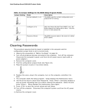
... AC power source. 11. Turn off all peripheral devices connected to normal mode. 1. Remove the computer cover. 46 Select Yes and press . Turn off the computer. Press and Setup displays a pop-up screen requesting that the board is set to the computer. Configure (2-3) Recovery (None) After the Power-On Self-Test (POST) runs, the BIOS displays the Maintenance Menu. Remove the computer cover. 4. Find the configuration jumper block (see Figure 22). 5. Intel Desktop Board DG41AN Product Guide...
... AC power source. 11. Turn off all peripheral devices connected to normal mode. 1. Remove the computer cover. 46 Select Yes and press . Turn off the computer. Press and Setup displays a pop-up screen requesting that the board is set to the computer. Configure (2-3) Recovery (None) After the Power-On Self-Test (POST) runs, the BIOS displays the Maintenance Menu. Remove the computer cover. 4. Find the configuration jumper block (see Figure 22). 5. Intel Desktop Board DG41AN Product Guide...


