Product Guide
Page 5
Contents 1 Desktop Board Features Supported Operating Systems 10 Desktop Board Components 11 Processor ...13 Main Memory...13 Intel® G33 Express Chipset 14 Intel G33 Graphics Subsystem 14 Audio Subsystem 16 Legacy Input/Output (I/O) Controller 16 LAN ...Subsystem 17 RJ-45 LAN Connector LEDs 17 Hi-Speed USB 2.0 Support 18 Enhanced IDE Interface 18 Serial ATA...18 Expandability...18 BIOS ...18 Serial ATA and IDE Auto Configuration 19 PCI and PCI...
Contents 1 Desktop Board Features Supported Operating Systems 10 Desktop Board Components 11 Processor ...13 Main Memory...13 Intel® G33 Express Chipset 14 Intel G33 Graphics Subsystem 14 Audio Subsystem 16 Legacy Input/Output (I/O) Controller 16 LAN ...Subsystem 17 RJ-45 LAN Connector LEDs 17 Hi-Speed USB 2.0 Support 18 Enhanced IDE Interface 18 Serial ATA...18 Expandability...18 BIOS ...18 Serial ATA and IDE Auto Configuration 19 PCI and PCI...
Product Guide
Page 6
Intel Desktop Board DG33BU Product Guide Installing and Removing a Processor 29 Installing a Processor 29 Installing the Processor Fan Heat Sink 32 Connecting the Processor Fan Heat Sink Cable 33 ... Configuration 34 Two or Four DIMMs 34 Three DIMMs 35 Installing DIMMs 36 Removing DIMMs 38 Installing and Removing a PCI Express x16 Card 39 Installing a PCI Express x16 Card 39 Removing the PCI Express x16 Card 40 Connecting the Diskette Drive Cable 41 Connecting the IDE Cable 42 Connecting the Serial ATA (SATA...
Intel Desktop Board DG33BU Product Guide Installing and Removing a Processor 29 Installing a Processor 29 Installing the Processor Fan Heat Sink 32 Connecting the Processor Fan Heat Sink Cable 33 ... Configuration 34 Two or Four DIMMs 34 Three DIMMs 35 Installing DIMMs 36 Removing DIMMs 38 Installing and Removing a PCI Express x16 Card 39 Installing a PCI Express x16 Card 39 Removing the PCI Express x16 Card 40 Connecting the Diskette Drive Cable 41 Connecting the IDE Cable 42 Connecting the Serial ATA (SATA...
Product Guide
Page 7
...49 25. Location of the Standby Power Indicator 22 4. Install the Processor 31 11. Installing a PCI Express x16 Card 39 19. Lift the Socket Lever 29 7. Removing a PCI Express x16 Card 40 20. Connecting a Serial ATA Cable 44 23. Internal Headers 45 24....the IDE Cable 43 22. Dual Channel Memory Configuration with Three DIMMs 35 16. Desktop Board DG33BU Mounting Screw Hole Locations 28 6. Close the Load Plate 32 12. Use DDR2 DIMMs 36 17. Desktop Board DG33BU Components 11 2. Installing a DIMM 37 18. Contents B Regulatory Compliance Safety Regulations...
...49 25. Location of the Standby Power Indicator 22 4. Install the Processor 31 11. Installing a PCI Express x16 Card 39 19. Lift the Socket Lever 29 7. Removing a PCI Express x16 Card 40 20. Connecting a Serial ATA Cable 44 23. Internal Headers 45 24....the IDE Cable 43 22. Dual Channel Memory Configuration with Three DIMMs 35 16. Desktop Board DG33BU Mounting Screw Hole Locations 28 6. Close the Load Plate 32 12. Use DDR2 DIMMs 36 17. Desktop Board DG33BU Components 11 2. Installing a DIMM 37 18. Contents B Regulatory Compliance Safety Regulations...
Product Guide
Page 9
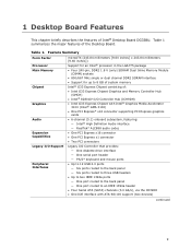
...features of Intel® Desktop Board DG33BU. 1 Desktop Board Features This chapter briefly describes the features of the Desktop Board. Feature Summary Form Factor Processor microATX (243.84 millimeters [9.60 inches] x 243.84 millimeters [9.60 inches]) Support for an Intel® processor... Intel® 82801IH I/O Controller Hub (ICH9DH) • Intel G33 Express Chipset with Intel® Graphics Media Accelerator 3100 (Intel® GMA 3100) • One PCI Express* x16 connector supporting PCI Express graphics cards • 6-channel (5.1) onboard subsystem, featuring: ― Intel...
...features of Intel® Desktop Board DG33BU. 1 Desktop Board Features This chapter briefly describes the features of the Desktop Board. Feature Summary Form Factor Processor microATX (243.84 millimeters [9.60 inches] x 243.84 millimeters [9.60 inches]) Support for an Intel® processor... Intel® 82801IH I/O Controller Hub (ICH9DH) • Intel G33 Express Chipset with Intel® Graphics Media Accelerator 3100 (Intel® GMA 3100) • One PCI Express* x16 connector supporting PCI Express graphics cards • 6-channel (5.1) onboard subsystem, featuring: ― Intel...
Product Guide
Page 10
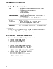
... • Wake on USB, PCI Express, PS/2, LAN, and front panel • ENGERY STAR* qualified desktop board Hardware Management Hardware monitor with: • Three fan sensing inputs used to monitor fan activity • Intel® Quiet System Technology fan speed...LAN controller Related Links: For more information about Desktop Board DG33BU, including the Technical Product Specification (TPS), BIOS updates, and device drivers, go to: http://support.intel.com/support/motherboards/desktop/ Supported Operating Systems The Desktop Board supports the following operating systems: • ...
... • Wake on USB, PCI Express, PS/2, LAN, and front panel • ENGERY STAR* qualified desktop board Hardware Management Hardware monitor with: • Three fan sensing inputs used to monitor fan activity • Intel® Quiet System Technology fan speed...LAN controller Related Links: For more information about Desktop Board DG33BU, including the Technical Product Specification (TPS), BIOS updates, and device drivers, go to: http://support.intel.com/support/motherboards/desktop/ Supported Operating Systems The Desktop Board supports the following operating systems: • ...
Product Guide
Page 12
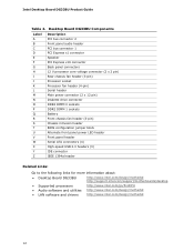
Intel Desktop Board DG33BU Product Guide Table 2. Desktop Board DG33BU Components Label A B C D E F G H I J K L M N O P Q R S T U V W X Y Z Description PCI bus connector 2 Front panel audio header PCI bus connector 1 PCI Express x1 connector Speaker PCI Express x16 connector Back panel connectors 12 V processor core voltage... Links: Go to the following links for more information about: • Desktop Board DG33BU http://www.intel.com/design/motherbd http://support.intel.com/support/motherboards/desktop • Supported processors • Audio software and utilities • LAN software ...
Intel Desktop Board DG33BU Product Guide Table 2. Desktop Board DG33BU Components Label A B C D E F G H I J K L M N O P Q R S T U V W X Y Z Description PCI bus connector 2 Front panel audio header PCI bus connector 1 PCI Express x1 connector Speaker PCI Express x16 connector Back panel connectors 12 V processor core voltage... Links: Go to the following links for more information about: • Desktop Board DG33BU http://www.intel.com/design/motherbd http://support.intel.com/support/motherboards/desktop • Supported processors • Audio software and utilities • LAN software ...
Product Guide
Page 14
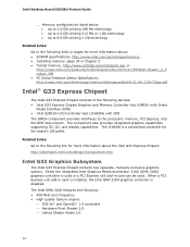
.../mbsearch.asp or http://www.intel.com/products/motherboard/index.htm?iid=HMPAGE+Header_2_P roduct_MB • PC Serial Presence Detect Specification, http://www.intel.com/technology/memory/ddr/specs/dda18c32_64_128x72aga.pdf Intel® G33 Express Chipset The Intel G33 Express Chipset consists of the..., PCI Express, and the DMI interconnect. Related Links: Go to the following : • 400 MHz core frequency • High quality texture engine: ⎯ DX9.0c* and OpenGL* 1.4 compliant ⎯ Hardware Pixel Shader 2.0 ⎯ Vertex Shader Model 2.0 14 Intel Desktop Board DG33BU Product...
.../mbsearch.asp or http://www.intel.com/products/motherboard/index.htm?iid=HMPAGE+Header_2_P roduct_MB • PC Serial Presence Detect Specification, http://www.intel.com/technology/memory/ddr/specs/dda18c32_64_128x72aga.pdf Intel® G33 Express Chipset The Intel G33 Express Chipset consists of the..., PCI Express, and the DMI interconnect. Related Links: Go to the following : • 400 MHz core frequency • High quality texture engine: ⎯ DX9.0c* and OpenGL* 1.4 compliant ⎯ Hardware Pixel Shader 2.0 ⎯ Vertex Shader Model 2.0 14 Intel Desktop Board DG33BU Product...
Product Guide
Page 16
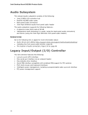
...Intel Desktop Board DG33BU Product Guide Audio Subsystem The onboard audio subsystem consists of the following: • Intel... • Audio drivers and utilities http://support.intel.com/support/motherboards/desktop/ • Installing the front panel audio solution,... page 46 • The location of 95 dB • Independent multi-streaming 5.1 audio (using the back panel audio connectors) and stereo (using the Intel...8226; Back panel audio connectors • Intel High Definition audio front panel audio header The audio subsystem ...
...Intel Desktop Board DG33BU Product Guide Audio Subsystem The onboard audio subsystem consists of the following: • Intel... • Audio drivers and utilities http://support.intel.com/support/motherboards/desktop/ • Installing the front panel audio solution,... page 46 • The location of 95 dB • Independent multi-streaming 5.1 audio (using the back panel audio connectors) and stereo (using the Intel...8226; Back panel audio connectors • Intel High Definition audio front panel audio header The audio subsystem ...
Product Guide
Page 17
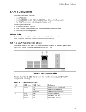
...100 Mb/s data rate 1000 Mb/s data rate 17 These LEDs indicate the status of the LAN. Desktop Board Features LAN Subsystem The LAN subsystem includes: • Intel® ICH9DH • Intel 82566DC Gigabit (10/100/1000 Mb/s) Ethernet LAN controller • RJ-45 LAN connector with integrated ...8226; LAN connect interface between ICH9DH and the LAN controller • PCI bus power management Related Links: Go to the following link for information about LAN software and drivers: http://support.intel.com/support/motherboards/desktop RJ-45 LAN Connector LEDs Two LEDs are built into the RJ-...
...100 Mb/s data rate 1000 Mb/s data rate 17 These LEDs indicate the status of the LAN. Desktop Board Features LAN Subsystem The LAN subsystem includes: • Intel® ICH9DH • Intel 82566DC Gigabit (10/100/1000 Mb/s) Ethernet LAN controller • RJ-45 LAN connector with integrated ...8226; LAN connect interface between ICH9DH and the LAN controller • PCI bus power management Related Links: Go to the following link for information about LAN software and drivers: http://support.intel.com/support/motherboards/desktop RJ-45 LAN Connector LEDs Two LEDs are built into the RJ-...
Product Guide
Page 18
...Gb/s) via the ICH9DH. The BIOS can be required to accommodate operating systems that fully support USB 2.0 transfer rates. Intel Desktop Board DG33BU Product Guide Hi-Speed USB 2.0 Support The Desktop Board supports up to 12 USB 2.0 ports (six ports routed to the back panel and six ports routed to three internal...such as hard disk drives and CD-ROM drives. This may be updated by following expansion slots: • One PCI Express x16 connector • One PCI Express x1 connector • Two PCI bus connectors BIOS The BIOS provides the Power-On Self-Test (POST), the BIOS Setup program, the...
...Gb/s) via the ICH9DH. The BIOS can be required to accommodate operating systems that fully support USB 2.0 transfer rates. Intel Desktop Board DG33BU Product Guide Hi-Speed USB 2.0 Support The Desktop Board supports up to 12 USB 2.0 ports (six ports routed to the back panel and six ports routed to three internal...such as hard disk drives and CD-ROM drives. This may be updated by following expansion slots: • One PCI Express x16 connector • One PCI Express x1 connector • Two PCI bus connectors BIOS The BIOS provides the Power-On Self-Test (POST), the BIOS Setup program, the...
Product Guide
Page 19
...only the supervisor password is set, pressing at the password prompt of Desktop Board DG33BU enable the board to run the BIOS Setup program after you install a PCI/PCI Express add-in card in your computer, the PCI/PCI Express auto-configuration utility in the BIOS Setup program. If both the ...be compatible with the following : • Fan speed monitoring and control • Thermal and voltage monitoring • Chassis intrusion detection 19 Desktop Board Features Serial ATA and IDE Auto Configuration If you install a Serial ATA or IDE device (such as a hard drive) in your computer...
...only the supervisor password is set, pressing at the password prompt of Desktop Board DG33BU enable the board to run the BIOS Setup program after you install a PCI/PCI Express add-in card in your computer, the PCI/PCI Express auto-configuration utility in the BIOS Setup program. If both the ...be compatible with the following : • Fan speed monitoring and control • Thermal and voltage monitoring • Chassis intrusion detection 19 Desktop Board Features Serial ATA and IDE Auto Configuration If you install a Serial ATA or IDE device (such as a hard drive) in your computer...
Product Guide
Page 22
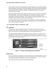
... necessary to support multiple wake events from the left-hand menu: http://support.intel.com/support/motherboards/desktop/ 22 When signaled by the LED turning amber. The Desktop Board supports the PCI Bus Power Management Interface Specification. Add-in cards that support this specification can participate... PCI bus connectors. Figure 3. Location of the Standby Power Indicator Related Links: For more information on the front panel, the sleep state is indicated by a wake-up device or event, the computer quickly returns to its last known awake state. Intel Desktop Board DG33BU ...
... necessary to support multiple wake events from the left-hand menu: http://support.intel.com/support/motherboards/desktop/ 22 When signaled by the LED turning amber. The Desktop Board supports the PCI Bus Power Management Interface Specification. Add-in cards that support this specification can participate... PCI bus connectors. Figure 3. Location of the Standby Power Indicator Related Links: For more information on the front panel, the sleep state is indicated by a wake-up device or event, the computer quickly returns to its last known awake state. Intel Desktop Board DG33BU ...
Product Guide
Page 23
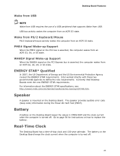
... see: http://www3.intel.com/cd/channel/reseller/asmo-na/eng/337748.htm. The speaker provides audible error code (beep code) information during the Power-On Self-Test (POST). The battery on the Desktop Board keeps the clock current when the computer is mounted on the PCI bus is asserted, the...or S5 state. Wake from PS/2 Keyboard/Mouse PS/2 keyboard/mouse activity wakes the computer from an ACPI S3, S4, or S5 state. Currently Intel Desktop Boards meet the new ENERGY STAR requirements. ENERGY STAR* Qualified In 2007, the US Department of -day clock and 100-year calendar. USB bus activity...
... see: http://www3.intel.com/cd/channel/reseller/asmo-na/eng/337748.htm. The speaker provides audible error code (beep code) information during the Power-On Self-Test (POST). The battery on the Desktop Board keeps the clock current when the computer is mounted on the PCI bus is asserted, the...or S5 state. Wake from PS/2 Keyboard/Mouse PS/2 keyboard/mouse activity wakes the computer from an ACPI S3, S4, or S5 state. Currently Intel Desktop Boards meet the new ENERGY STAR requirements. ENERGY STAR* Qualified In 2007, the US Department of -day clock and 100-year calendar. USB bus activity...
Product Guide
Page 25
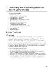
... This chapter tells you how to: • Install the I/O shield • Install and remove the Desktop Board • Install and remove a processor • Install and remove memory • Install and remove a PCI Express x16 card • Connect the diskette drive cable • Connect the IDE and Serial ATA cables • ... before performing any procedures can damage components. If such a station is off. Perform the procedures described in this chapter. Some circuitry on the board can continue to a metal part of the procedures described in personal injury or equipment damage.
... This chapter tells you how to: • Install the I/O shield • Install and remove the Desktop Board • Install and remove a processor • Install and remove memory • Install and remove a PCI Express x16 card • Connect the diskette drive cable • Connect the IDE and Serial ATA cables • ... before performing any procedures can damage components. If such a station is off. Perform the procedures described in this chapter. Some circuitry on the board can continue to a metal part of the procedures described in personal injury or equipment damage.
Product Guide
Page 39
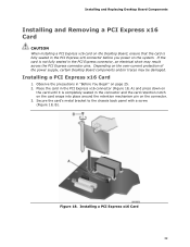
... over-current protection of the power supply, certain Desktop Board components and/or traces may result across the PCI Express connector pins. Installing a PCI Express x16 Card 39 Installing and Replacing Desktop Board Components Installing and Removing a PCI Express x16 Card CAUTION When installing a PCI Express x16 card on the Desktop Board, ensure that the card is completely seated in...
... over-current protection of the power supply, certain Desktop Board components and/or traces may result across the PCI Express connector pins. Installing a PCI Express x16 Card 39 Installing and Replacing Desktop Board Components Installing and Removing a PCI Express x16 Card CAUTION When installing a PCI Express x16 card on the Desktop Board, ensure that the card is completely seated in...
Product Guide
Page 40
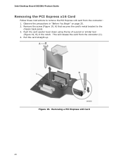
Push the card ejector lever down using the tip of a pencil or similar tool (Figure 19, B) in "Before You Begin" on page 25. 2. This will release the card from the connector: 1. Intel Desktop Board DG33BU Product Guide Removing the PCI Express x16 Card Follow these instructions to the chassis back panel. 3. Pull the card straight up. Observe the precautions in the notch. Figure 19. Remove the screw (Figure 19, A) that secures the card's metal bracket to remove the PCI Express x16 card from the connector (C). 4. Removing a PCI Express x16 Card 40
Push the card ejector lever down using the tip of a pencil or similar tool (Figure 19, B) in "Before You Begin" on page 25. 2. This will release the card from the connector: 1. Intel Desktop Board DG33BU Product Guide Removing the PCI Express x16 Card Follow these instructions to the chassis back panel. 3. Pull the card straight up. Observe the precautions in the notch. Figure 19. Remove the screw (Figure 19, A) that secures the card's metal bracket to remove the PCI Express x16 card from the connector (C). 4. Removing a PCI Express x16 Card 40

