
Product Guide
Page 5
...Systems 10 Desktop Board Components 11 Processor ...13 Main Memory...13 Intel® G31 Express Chipset 14 Intel® G33 Graphics Subsystem 15 Intel® GMA 3100 Graphics Controller (Intel® GMA 3100 15 Audio Subsystem 16 Legacy Input/Output (I/O)... Controller 17 LAN Subsystem 17 RJ-45 LAN Connector LEDs 17 Hi-Speed USB 2.0 Support 18 Enhanced IDE Interface 18 Serial ATA...18 Expandability...19 BIOS ...19 Serial ATA and IDE Auto Configuration 19 PCI* and PCI Express...
...Systems 10 Desktop Board Components 11 Processor ...13 Main Memory...13 Intel® G31 Express Chipset 14 Intel® G33 Graphics Subsystem 15 Intel® GMA 3100 Graphics Controller (Intel® GMA 3100 15 Audio Subsystem 16 Legacy Input/Output (I/O)... Controller 17 LAN Subsystem 17 RJ-45 LAN Connector LEDs 17 Hi-Speed USB 2.0 Support 18 Enhanced IDE Interface 18 Serial ATA...18 Expandability...19 BIOS ...19 Serial ATA and IDE Auto Configuration 19 PCI* and PCI Express...
Product Guide
Page 6
Intel Desktop Board DG31PR Product Guide Installing and Removing a Processor 31 Installing a Processor 31 Installing the Processor Fan Heat Sink 34 Connecting the Processor Fan Heat Sink Cable 35 Removing the Processor 36 Installing and Removing Memory 36 Installing DIMMs 37 Removing DIMMs 39 Installing and Removing a PCI Express x16 Card 39 Installing a PCI Express... x16 Card 40 Removing the PCI Express x16 Card 41 Connecting the Diskette Drive Cable 42 Connecting ...
Intel Desktop Board DG31PR Product Guide Installing and Removing a Processor 31 Installing a Processor 31 Installing the Processor Fan Heat Sink 34 Connecting the Processor Fan Heat Sink Cable 35 Removing the Processor 36 Installing and Removing Memory 36 Installing DIMMs 37 Removing DIMMs 39 Installing and Removing a PCI Express x16 Card 39 Installing a PCI Express... x16 Card 40 Removing the PCI Express x16 Card 41 Connecting the Diskette Drive Cable 42 Connecting ...
Product Guide
Page 7
...Lead-Free Board Markings 70 16. Location of the Chassis Fan Headers 50 24. Connecting the Diskette Drive Cable 42 19. Removing a PCI Express x16 Card 41 18. Connecting a Serial ATA Cable 44 21. USB 2.0 Header Signal Names 48 11. Beep Codes 63 13. ...Cables 51 25. Chassis Intrusion Header 46 7. LAN Connector LEDs 17 3. Front Panel Intel High Definition Audio Header Signal Names 46 5. Desktop Board DG31PR Components 11 2. S/PDIF Connector 46 6. Installing a PCI Express x16 Card 40 17. Connecting the IDE Cable 43 20. Desktop Board DG31PR Components 12...
...Lead-Free Board Markings 70 16. Location of the Chassis Fan Headers 50 24. Connecting the Diskette Drive Cable 42 19. Removing a PCI Express x16 Card 41 18. Connecting a Serial ATA Cable 44 21. USB 2.0 Header Signal Names 48 11. Beep Codes 63 13. ...Cables 51 25. Chassis Intrusion Header 46 7. LAN Connector LEDs 17 3. Front Panel Intel High Definition Audio Header Signal Names 46 5. Desktop Board DG31PR Components 11 2. S/PDIF Connector 46 6. Installing a PCI Express x16 Card 40 17. Connecting the IDE Cable 43 20. Desktop Board DG31PR Components 12...
Product Guide
Page 9
... chapter briefly describes the features of : • Intel G31 Express Chipset Graphics and Memory Controller Hub (GMCH) with Intel® Graphics Media Accelerator 3100 (Intel® GMA 3100) • Intel® 82801G I/O Controller Hub (ICH7) • Intel G31 Express Chipset Graphics and Memory Controller Hub (GMCH) • One PCI Express* x16 connector supporting PCI Express graphics cards • 5.1 + 2-channel onboard audio...
... chapter briefly describes the features of : • Intel G31 Express Chipset Graphics and Memory Controller Hub (GMCH) with Intel® Graphics Media Accelerator 3100 (Intel® GMA 3100) • Intel® 82801G I/O Controller Hub (ICH7) • Intel G31 Express Chipset Graphics and Memory Controller Hub (GMCH) • One PCI Express* x16 connector supporting PCI Express graphics cards • 5.1 + 2-channel onboard audio...
Product Guide
Page 10
...device • Support for SMBIOS • Intel® Rapid BIOS Boot • Intel® Express BIOS Update Power Management • Support for Advanced Configuration and Power Interface (ACPI) • Suspend to RAM (STR) • Wake on USB, PCI Express, LAN, and front panel • ENERGY...about Desktop Board DG31PR, including the Technical Product Specification (TPS), BIOS updates, and device drivers, go to: http://support.intel.com/support/motherboards/desktop/ Supported Operating Systems The Desktop Board supports the following operating systems: • Microsoft Windows Vista* ...
...device • Support for SMBIOS • Intel® Rapid BIOS Boot • Intel® Express BIOS Update Power Management • Support for Advanced Configuration and Power Interface (ACPI) • Suspend to RAM (STR) • Wake on USB, PCI Express, LAN, and front panel • ENERGY...about Desktop Board DG31PR, including the Technical Product Specification (TPS), BIOS updates, and device drivers, go to: http://support.intel.com/support/motherboards/desktop/ Supported Operating Systems The Desktop Board supports the following operating systems: • Microsoft Windows Vista* ...
Product Guide
Page 14
... Installing memory, page 36 in Chapter 2 • Tested memory, http://www.cmtlabs.com/mbsearch.asp Intel® G31 Express Chipset The Intel G31 Express Chipset consists of the following devices: • Intel G31 Express Chipset Graphics and Memory Controller Hub (GMCH) with DMI The GMCH component provides interfaces to the following ...Gb technology Related Links: Go to the following link for the board's I /O Controller Hub (ICH7) with Direct Media Interface (DMI) • Intel 82801G I /O paths. Related Links: Go to the processor, memory, PCI Express, and the DMI interconnect.
... Installing memory, page 36 in Chapter 2 • Tested memory, http://www.cmtlabs.com/mbsearch.asp Intel® G31 Express Chipset The Intel G31 Express Chipset consists of the following devices: • Intel G31 Express Chipset Graphics and Memory Controller Hub (GMCH) with DMI The GMCH component provides interfaces to the following ...Gb technology Related Links: Go to the following link for the board's I /O Controller Hub (ICH7) with Direct Media Interface (DMI) • Intel 82801G I /O paths. Related Links: Go to the processor, memory, PCI Express, and the DMI interconnect.
Product Guide
Page 15
... 3100) graphics controller is disabled. When a PCI Express x16 add-in card is installed, the Intel GMA 3100 graphics controller is used or a PCI Express x16 add-in order for the Intel GMA 3100 integrated graphics controller to operate properly. 15 Intel® GMA 3100 Graphics Controller (Intel® GMA 3100) The Intel GMA 3100 features the following: •...
... 3100) graphics controller is disabled. When a PCI Express x16 add-in card is installed, the Intel GMA 3100 graphics controller is used or a PCI Express x16 add-in order for the Intel GMA 3100 integrated graphics controller to operate properly. 15 Intel® GMA 3100 Graphics Controller (Intel® GMA 3100) The Intel GMA 3100 features the following: •...
Product Guide
Page 19
...stored in the BIOS Setup program. You do not need to run the BIOS Setup program after installing a Serial ATA or IDE device. PCI* and PCI Express* Auto Configuration If you install a Serial ATA or IDE device (such as a hard drive) in your computer, the auto-configuration ...utility in the BIOS automatically detects and configures the device for your computer, the PCI/PCI Express auto-configuration utility in the BIOS automatically detects and configures the resources (IRQs, DMA channels, and I/O space) for that add-in card. ...
...stored in the BIOS Setup program. You do not need to run the BIOS Setup program after installing a Serial ATA or IDE device. PCI* and PCI Express* Auto Configuration If you install a Serial ATA or IDE device (such as a hard drive) in your computer, the auto-configuration ...utility in the BIOS automatically detects and configures the device for your computer, the PCI/PCI Express auto-configuration utility in the BIOS automatically detects and configures the resources (IRQs, DMA channels, and I/O space) for that add-in card. ...
Product Guide
Page 25
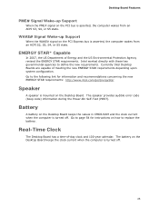
... meeting the new ENERGY STAR requirements depending upon system configuration. The battery on the Desktop Board. Go to replace the battery. Intel worked directly with these two governmental agencies to page 54 for information and recommendations concerning the new ENERGY STAR requirements: http://www...year calendar. Desktop Board Features PME# Signal Wake-up Support When the WAKE# signal on how to the following link for instructions on the PCI Express bus is asserted, the computer wakes from an ACPI S3, S4, or S5 state. The speaker provides audible error code (beep code) ...
... meeting the new ENERGY STAR requirements depending upon system configuration. The battery on the Desktop Board. Go to replace the battery. Intel worked directly with these two governmental agencies to page 54 for information and recommendations concerning the new ENERGY STAR requirements: http://www...year calendar. Desktop Board Features PME# Signal Wake-up Support When the WAKE# signal on how to the following link for instructions on the PCI Express bus is asserted, the computer wakes from an ACPI S3, S4, or S5 state. The speaker provides audible error code (beep code) ...
Product Guide
Page 27
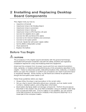
...: • Install the I/O shield • Install and remove the Desktop Board • Install and remove a processor • Install and remove memory • Install and remove a PCI Express x16 card • Connect the diskette drive cable • Connect the IDE and Serial ATA cables • Connect to the internal headers and connectors •...
...: • Install the I/O shield • Install and remove the Desktop Board • Install and remove a processor • Install and remove memory • Install and remove a PCI Express x16 card • Connect the diskette drive cable • Connect the IDE and Serial ATA cables • Connect to the internal headers and connectors •...
Product Guide
Page 39
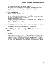
...AC power cord. When the DIMM is fully seated in an anti-static package. 7. Hold the DIMM by the edges, lift it in the PCI Express x16 connector before you removed or disconnected to the computer. If the card is not fully seated in place. 9. Turn off the computer. 3....1. Gently spread the retaining clips at each end of the socket. 6. Depending on page 27. 2. Make sure the clips are firmly in the PCI Express connector, an electrical short may be damaged. 39 Installing and Replacing Desktop Board Components 7. Insert the bottom edge of the power supply, certain Desktop ...
...AC power cord. When the DIMM is fully seated in an anti-static package. 7. Hold the DIMM by the edges, lift it in the PCI Express x16 connector before you removed or disconnected to the computer. If the card is not fully seated in place. 9. Turn off the computer. 3....1. Gently spread the retaining clips at each end of the socket. 6. Depending on page 27. 2. Make sure the clips are firmly in the PCI Express connector, an electrical short may be damaged. 39 Installing and Replacing Desktop Board Components 7. Insert the bottom edge of the power supply, certain Desktop ...
Product Guide
Page 40
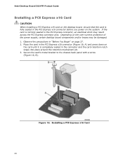
... down on the system. Installing a PCI Express x16 Card 40 Secure the card's metal bracket to the chassis back panel with a screw (Figure 16, B). Figure 16. Intel Desktop Board DG31PR Product Guide Installing a PCI Express x16 Card CAUTION When installing a PCI Express x16 card on the desktop board, ...ensure that the card is fully seated in the PCI Express x16 connector before you power on the card until...
... down on the system. Installing a PCI Express x16 Card 40 Secure the card's metal bracket to the chassis back panel with a screw (Figure 16, B). Figure 16. Intel Desktop Board DG31PR Product Guide Installing a PCI Express x16 Card CAUTION When installing a PCI Express x16 card on the desktop board, ...ensure that the card is fully seated in the PCI Express x16 connector before you power on the card until...
Product Guide
Page 41
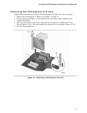
Figure 17. Push the card ejector lever down using the tip of a pencil or similar tool in "Before You Begin" on page 27. 2. Pull the card straight up. Removing a PCI Express x16 Card 41 Remove the screw (Figure 17, A) that secures the card's metal bracket to remove the PCI Express x16 card from the connector (Figure 17, C). 4. This will release the card from the connector: 1. Installing and Replacing Desktop Board Components Removing the PCI Express x16 Card Follow these instructions to the chassis back panel. 3. Observe the precautions in the notch (Figure 17, B).
Figure 17. Push the card ejector lever down using the tip of a pencil or similar tool in "Before You Begin" on page 27. 2. Pull the card straight up. Removing a PCI Express x16 Card 41 Remove the screw (Figure 17, A) that secures the card's metal bracket to remove the PCI Express x16 card from the connector (Figure 17, C). 4. This will release the card from the connector: 1. Installing and Replacing Desktop Board Components Removing the PCI Express x16 Card Follow these instructions to the chassis back panel. 3. Observe the precautions in the notch (Figure 17, B).

