
Technical Product Specification
Page 29
...and PCH VCC • SMBus interface 1.10.2 Fan Monitoring Fan monitoring can be compatible with the Wired for Management (WfM) specification. The security feature uses a mechanical switch on the Nuvoton NCT6776D device, which supports the following: • Processor and system ambient temperature monitoring • Chassis fan speed monitoring • Power monitoring ... cover is in the closed position. Product Description 1.10 Hardware Management Subsystem The hardware management features enable the board to be implemented using Intel® Desktop Utilities or third-party software.
...and PCH VCC • SMBus interface 1.10.2 Fan Monitoring Fan monitoring can be compatible with the Wired for Management (WfM) specification. The security feature uses a mechanical switch on the Nuvoton NCT6776D device, which supports the following: • Processor and system ambient temperature monitoring • Chassis fan speed monitoring • Power monitoring ... cover is in the closed position. Product Description 1.10 Hardware Management Subsystem The hardware management features enable the board to be implemented using Intel® Desktop Utilities or third-party software.
Technical Product Specification
Page 51
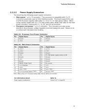
...that cable to the processor voltage regulator and must always be unconnected. Failure to Section 2.6.1 on Intel Desktop boards. For ...information about Power supply considerations Refer to do so will be used on page 58 51 This connector provides power directly to the main power connector, leaving pins 11, 12, 23, and 24 unconnected. • Processor... either 2 x 10 or 2 x 12 main power cables. a 2 x 12 connector. a 2 x 2 connector. Processor Core Power Connector Pin Signal Name Pin Signal Name 1 Ground 2 Ground 3 +12 V 4 +12 V Table 25....
...that cable to the processor voltage regulator and must always be unconnected. Failure to Section 2.6.1 on Intel Desktop boards. For ...information about Power supply considerations Refer to do so will be used on page 58 51 This connector provides power directly to the main power connector, leaving pins 11, 12, 23, and 24 unconnected. • Processor... either 2 x 10 or 2 x 12 main power cables. a 2 x 12 connector. a 2 x 2 connector. Processor Core Power Connector Pin Signal Name Pin Signal Name 1 Ground 2 Ground 3 +12 V 4 +12 V Table 25....


