
Technical Product Specification
Page 7
... 1.5.3 USB 23 1.5.4 SATA Interfaces 23 1.6 Real-Time Clock Subsystem 24 1.7 Legacy I/O Controller 24 1.8 Audio Subsystem 25 1.8.1 Audio Subsystem Software 25 1.8.2 Audio Connectors and Headers 26 1.9 LAN Subsystem 27 1.9.1 Intel® 82579V Gigabit Ethernet Controller 27 1.9.2 LAN Subsystem Software 28 1.9.3 RJ-45 LAN Connector with Integrated LEDs 28 1.10 Hardware Management Subsystem 29 1.10.1 Hardware Monitoring 29...
... 1.5.3 USB 23 1.5.4 SATA Interfaces 23 1.6 Real-Time Clock Subsystem 24 1.7 Legacy I/O Controller 24 1.8 Audio Subsystem 25 1.8.1 Audio Subsystem Software 25 1.8.2 Audio Connectors and Headers 26 1.9 LAN Subsystem 27 1.9.1 Intel® 82579V Gigabit Ethernet Controller 27 1.9.2 LAN Subsystem Software 28 1.9.3 RJ-45 LAN Connector with Integrated LEDs 28 1.10 Hardware Management Subsystem 29 1.10.1 Hardware Monitoring 29...
Technical Product Specification
Page 9
.... Memory Channel and DIMM Configuration 21 4. Components Shown in Figure 1 14 4. Back Panel Audio Connectors 26 5. Major Board Components 13 2. Audio Jack Support 25 ix Back Panel Connectors 44 11. Connection Diagram for Front Panel Header 52 13. Intel Desktop Board DB75EN China RoHS Material Self Declaration Table 86 Tables 1. Localized High Temperature Zones 60 18...
.... Memory Channel and DIMM Configuration 21 4. Components Shown in Figure 1 14 4. Back Panel Audio Connectors 26 5. Major Board Components 13 2. Audio Jack Support 25 ix Back Panel Connectors 44 11. Connection Diagram for Front Panel Header 52 13. Intel Desktop Board DB75EN China RoHS Material Self Declaration Table 86 Tables 1. Localized High Temperature Zones 60 18...
Technical Product Specification
Page 10
...Port Header 47 14. Front Panel USB 3.0 Connector 48 18. SATA Connectors 48 19. States for BIOS Recovery 67 41. Alternate Front Panel Power/Sleep LED Header 53 30. BIOS Beep Codes 73 44. Safety Standards 81 50. Intel Desktop Board DB75EN Technical Product Specification 6. Effects of Pressing the ...Two-Color Power LED 53 29. S/PDIF Header 48 20. Processor Core Power Connector 51 25. States for AC '97 Audio 47 16. Intel MEBX Reset Header Signals 56 32. Thermal Considerations for Intel HD Audio 47 15. Boot Device Menu Options 68 42. Port 80h POST Codes 76 48...
...Port Header 47 14. Front Panel USB 3.0 Connector 48 18. SATA Connectors 48 19. States for BIOS Recovery 67 41. Alternate Front Panel Power/Sleep LED Header 53 30. BIOS Beep Codes 73 44. Safety Standards 81 50. Intel Desktop Board DB75EN Technical Product Specification 6. Effects of Pressing the ...Two-Color Power LED 53 29. S/PDIF Header 48 20. Processor Core Power Connector 51 25. States for AC '97 Audio 47 16. Intel MEBX Reset Header Signals 56 32. Thermal Considerations for Intel HD Audio 47 15. Boot Device Menu Options 68 42. Port 80h POST Codes 76 48...
Technical Product Specification
Page 26
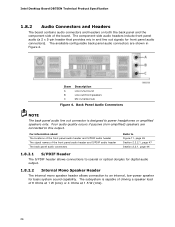
... and line out signals for basic system sound capability. Intel Desktop Board DB75EN Technical Product Specification 1.8.2 Audio Connectors and Headers The board contains audio connectors and headers on both the back panel and the component side of the front panel audio header and S/PDIF audio header The back panel audio connectors Refer to Figure 11, page 45 Section 2.2.2.1, page 47...
... and line out signals for basic system sound capability. Intel Desktop Board DB75EN Technical Product Specification 1.8.2 Audio Connectors and Headers The board contains audio connectors and headers on both the back panel and the component side of the front panel audio header and S/PDIF audio header The back panel audio connectors Refer to Figure 11, page 45 Section 2.2.2.1, page 47...

Technical Product Specification
Page 44
... Poor audio quality occurs if passive (non-amplified) speakers are connected to power headphones or amplified speakers only. Item A B C D E F G H I J K Description PS/2 port USB 2.0 ports USB 2.0 ports VGA connector Parallel port DVI-D connector LAN port USB 3.0 ports Line in/surround Line out/front speakers Mic-in/center/subwoofer Figure 10. Intel Desktop Board DB75EN Technical Product...
... Poor audio quality occurs if passive (non-amplified) speakers are connected to power headphones or amplified speakers only. Item A B C D E F G H I J K Description PS/2 port USB 2.0 ports USB 2.0 ports VGA connector Parallel port DVI-D connector LAN port USB 3.0 ports Line in/surround Line out/front speakers Mic-in/center/subwoofer Figure 10. Intel Desktop Board DB75EN Technical Product...

Technical Product Specification
Page 46
...connector B Conventional PCI add-in card connector C PCI Express x1 add-in card connector D PCI Express x16 add-in Figure 11. Intel Desktop Board DB75EN Technical Product Specification Table 12 lists the component-side connectors and headers identified in card connector E 12 V processor core voltage connector...L Main power connector (2 x 12) M Intel MEBX reset header N SATA 6.0 Gb/s connector (blue) O eSATA 3.0 Gb/s connector (red) P Alternate front panel power/sleep LED header Q Front panel header R SATA 3.0 connectors (black) S Front panel USB 3.0 connector (blue) T...
...connector B Conventional PCI add-in card connector C PCI Express x1 add-in card connector D PCI Express x16 add-in Figure 11. Intel Desktop Board DB75EN Technical Product Specification Table 12 lists the component-side connectors and headers identified in card connector E 12 V processor core voltage connector...L Main power connector (2 x 12) M Intel MEBX reset header N SATA 6.0 Gb/s connector (blue) O eSATA 3.0 Gb/s connector (red) P Alternate front panel power/sleep LED header Q Front panel header R SATA 3.0 connectors (black) S Front panel USB 3.0 connector (blue) T...

Technical Product Specification
Page 47
...8 CTS (Clear To Send) 10 Key (no pin) 10 Signal Name +5 V DC DD+ Ground No Connect 47 Front Panel Audio Header for AC '97 Audio Pin Signal Name Pin Signal Name 1 MIC 3 MIC_BIAS 5 FP_OUT_R 2 AUD_GND 4 AUD_GND 6 FP_RETURN_R 7 AUD_5V 9 FP_OUT_L 8 KEY...USB 2.0 Headers Pin Signal Name Pin 1 +5 V DC 2 3 D- 4 5 D+ 6 7 Ground 8 9 KEY (no pin) Table 14. Front Panel Audio Header for Intel HD Audio Pin Signal Name Pin Signal Name 1 [Port 1] Left channel 2 Ground 3 [Port 1] Right channel 4 PRESENCE# (Dongle present) 5 [Port 2] Right channel...
...8 CTS (Clear To Send) 10 Key (no pin) 10 Signal Name +5 V DC DD+ Ground No Connect 47 Front Panel Audio Header for AC '97 Audio Pin Signal Name Pin Signal Name 1 MIC 3 MIC_BIAS 5 FP_OUT_R 2 AUD_GND 4 AUD_GND 6 FP_RETURN_R 7 AUD_5V 9 FP_OUT_L 8 KEY...USB 2.0 Headers Pin Signal Name Pin 1 +5 V DC 2 3 D- 4 5 D+ 6 7 Ground 8 9 KEY (no pin) Table 14. Front Panel Audio Header for Intel HD Audio Pin Signal Name Pin Signal Name 1 [Port 1] Left channel 2 Ground 3 [Port 1] Right channel 4 PRESENCE# (Dongle present) 5 [Port 2] Right channel...


