

Product Guide
Page 5
Contents 1 Desktop Board Features Supported Operating Systems 10 Desktop Board Components 11 Processor...13 Main Memory ...14 Intel® 945P Express Chipset 15 Graphics Subsystem ...15 Audio Subsystem ...15 Input/Output (I/O) Controller 16 LAN Subsystem ...16 LAN Subsystem ...Configuration 18 Security Passwords ...18 Chassis Intrusion...19 Power Management Features 19 ACPI...19 Power Connectors...19 Fan Connectors...19 Fan Speed Control (Intel® Precision Cooling Technology 19 Suspend to RAM (Instantly Available PC Technology 20 Wake from USB...21 Wake from PS/2 Keyboard/Mouse 21...
Contents 1 Desktop Board Features Supported Operating Systems 10 Desktop Board Components 11 Processor...13 Main Memory ...14 Intel® 945P Express Chipset 15 Graphics Subsystem ...15 Audio Subsystem ...15 Input/Output (I/O) Controller 16 LAN Subsystem ...16 LAN Subsystem ...Configuration 18 Security Passwords ...18 Chassis Intrusion...19 Power Management Features 19 ACPI...19 Power Connectors...19 Fan Connectors...19 Fan Speed Control (Intel® Precision Cooling Technology 19 Suspend to RAM (Instantly Available PC Technology 20 Wake from USB...21 Wake from PS/2 Keyboard/Mouse 21...

Product Guide
Page 6
Intel Desktop Board D945PSN Product Guide Installing and Removing the Desktop Board 27 Installing and Removing a Processor 28 Installing a Processor 28 Installing the Processor Fan Heat Sink 31 Connecting the Processor Fan Heat Sink Cable 31 Removing the Processor 31 Installing and Removing Memory 32 Installing DIMMs...... Cable 37 Connecting the Serial ATA (SATA) Cable 38 Connecting Internal Headers 39 Installing a Front Panel Audio Solution for Intel® High Definition Audio 40 Connecting USB 2.0 Headers 41 Connecting IEEE 1394a Headers 41 Connecting the Front Panel Header 41...
Intel Desktop Board D945PSN Product Guide Installing and Removing the Desktop Board 27 Installing and Removing a Processor 28 Installing a Processor 28 Installing the Processor Fan Heat Sink 31 Connecting the Processor Fan Heat Sink Cable 31 Removing the Processor 31 Installing and Removing Memory 32 Installing DIMMs...... Cable 37 Connecting the Serial ATA (SATA) Cable 38 Connecting Internal Headers 39 Installing a Front Panel Audio Solution for Intel® High Definition Audio 40 Connecting USB 2.0 Headers 41 Connecting IEEE 1394a Headers 41 Connecting the Front Panel Header 41...
Product Guide
Page 7
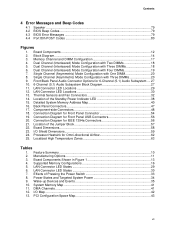
... Panel Header Signal Names 41 11. BIOS Error Messages 57 14. Lift Socket Lever ...28 7. Install Processor ...30 11. Back Panel Audio Connectors for Intel® High Definition Audio 40 7. Location of Standby Power Indicator 20 4. Location of the BIOS Configuration ...Signal Names 41 9. Product Certification Markings 66 vii Remove the Processor from the Protective Processor Cover/Do Not Touch 29 10. Inserting a PCI Express x16 Card 36 18. Desktop Board D945PSN Components 12 3. Desktop Board D945PSN Memory Configurations 14 5. Lead-Free Board Markings 64 16. ...
... Panel Header Signal Names 41 11. BIOS Error Messages 57 14. Lift Socket Lever ...28 7. Install Processor ...30 11. Back Panel Audio Connectors for Intel® High Definition Audio 40 7. Location of Standby Power Indicator 20 4. Location of the BIOS Configuration ...Signal Names 41 9. Product Certification Markings 66 vii Remove the Processor from the Protective Processor Cover/Do Not Touch 29 10. Inserting a PCI Express x16 Card 36 18. Desktop Board D945PSN Components 12 3. Desktop Board D945PSN Memory Configurations 14 5. Lead-Free Board Markings 64 16. ...
Product Guide
Page 9
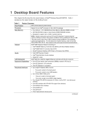
... the latest list of tested memory, refer to the Intel World Wide Web site at: http://support.intel.com/support/motherboards/desktop/ Intel® 945P Express Chipset consisting of memory being available to 4 GB of Intel® Desktop Board D945PSN. Table 1. Feature Summary Form Factors Processor Main Memory Chipset Audio LAN Subsystem Expansion Capabilities Peripheral Interfaces...
... the latest list of tested memory, refer to the Intel World Wide Web site at: http://support.intel.com/support/motherboards/desktop/ Intel® 945P Express Chipset consisting of memory being available to 4 GB of Intel® Desktop Board D945PSN. Table 1. Feature Summary Form Factors Processor Main Memory Chipset Audio LAN Subsystem Expansion Capabilities Peripheral Interfaces...
Product Guide
Page 12
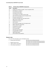
... the following links for more information about: • Desktop Board D945PSN • Supported processors • Audio software and utilities • LAN software and drivers http://www.intel.com/design/motherbd http://support.intel.com/support/motherboards/desktop http://support.intel.com/support/motherboards/desktop http://www.intel.com/design/motherbd http://www.intel.com/design/motherbd 12
... the following links for more information about: • Desktop Board D945PSN • Supported processors • Audio software and utilities • LAN software and drivers http://www.intel.com/design/motherbd http://support.intel.com/support/motherboards/desktop http://support.intel.com/support/motherboards/desktop http://www.intel.com/design/motherbd http://www.intel.com/design/motherbd 12

Product Guide
Page 13
... and 19 A peak current for 10mS ATX12V (version 2.0 or greater) compliant Power Supply Desktop Board D945PSN supports an Intel processor in Chapter 2 13 Table 3. The supported processors list for Desktop Board D945PSN is located on the web at: http://support.intel.com/support/motherboards/desktop/ Related Links: Go to the following links or pages for more...
... and 19 A peak current for 10mS ATX12V (version 2.0 or greater) compliant Power Supply Desktop Board D945PSN supports an Intel processor in Chapter 2 13 Table 3. The supported processors list for Desktop Board D945PSN is located on the web at: http://support.intel.com/support/motherboards/desktop/ Related Links: Go to the following links or pages for more...

Product Guide
Page 17
... and drivers that meets the requirements for a full-speed USB device. Enhanced IDE Interface The ICH7's IDE interface handles the exchange of information between the processor and peripheral devices like hard disks, CD-ROM drives, and Iomega Zip* drives inside the computer. Table 5. This may be required to accommodate operating systems...
... and drivers that meets the requirements for a full-speed USB device. Enhanced IDE Interface The ICH7's IDE interface handles the exchange of information between the processor and peripheral devices like hard disks, CD-ROM drives, and Iomega Zip* drives inside the computer. Table 5. This may be required to accommodate operating systems...
Product Guide
Page 19
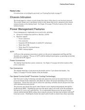
... fan. Power Connectors The desktop board has three power connectors. The use of ACPI with Intel® boxed processors. Fan Speed Control (Intel® Precision Cooling Technology) Intel Precision Cooling Technology automatically adjusts the processor fan speed based on the processor thermal diode temperature and adjusts the chassis fan speeds depending on page 47. The security...
... fan. Power Connectors The desktop board has three power connectors. The use of ACPI with Intel® boxed processors. Fan Speed Control (Intel® Precision Cooling Technology) Intel Precision Cooling Technology automatically adjusts the processor fan speed based on the processor thermal diode temperature and adjusts the chassis fan speeds depending on page 47. The security...
Product Guide
Page 23
... any telecommunications links, networks, or modems before you how to: • Install the I/O shield • Install and remove the desktop board • Install and remove a processor and memory • Install and remove a PCI Express x16 card • Connect the IDE and Serial ATA cables • Connect internal headers • Set up...
... any telecommunications links, networks, or modems before you how to: • Install the I/O shield • Install and remove the desktop board • Install and remove a processor and memory • Install and remove a PCI Express x16 card • Connect the IDE and Serial ATA cables • Connect internal headers • Set up...

Product Guide
Page 24
...computer integration, make sure that could be careful of the computer chassis. Perform the procedures described in this board. Intel Desktop Board D945PSN Product Guide Follow these guidelines before you begin: • Always follow these instructions and the instructions provided by ... • Sharp pins on printed circuit assemblies • Rough edges and sharp corners on the chassis • Hot components (like processors, voltage regulators, and heat sinks) • Damage to the following when reading the installation instructions for the chassis are marked accordingly...
...computer integration, make sure that could be careful of the computer chassis. Perform the procedures described in this board. Intel Desktop Board D945PSN Product Guide Follow these guidelines before you begin: • Always follow these instructions and the instructions provided by ... • Sharp pins on printed circuit assemblies • Rough edges and sharp corners on the chassis • Hot components (like processors, voltage regulators, and heat sinks) • Damage to the following when reading the installation instructions for the chassis are marked accordingly...

Product Guide
Page 28
... been removed by pushing the lever down and away from the computer; To install a processor, follow these instructions: 1. Intel Desktop Board D945PSN Product Guide Installing and Removing a Processor Instructions on how to install the processor to do so could damage the processor and the board. Do not touch the socket contacts (see Figure 7, C and D) C D D OM17211 Figure...
... been removed by pushing the lever down and away from the computer; To install a processor, follow these instructions: 1. Intel Desktop Board D945PSN Product Guide Installing and Removing a Processor Instructions on how to install the processor to do so could damage the processor and the board. Do not touch the socket contacts (see Figure 7, C and D) C D D OM17211 Figure...

Product Guide
Page 29
... the edges, being careful not to the package if the processor is removed from the protective processor cover. OM17213 Figure 9. Do not discard the protective processor cover. OM17228 Figure 8. Remove the plastic protective socket cover from the socket. Remove the Processor from the Protective Processor Cover/Do Not Touch 29 Do not discard the protective...
... the edges, being careful not to the package if the processor is removed from the protective processor cover. OM17213 Figure 9. Do not discard the protective processor cover. OM17228 Figure 8. Remove the plastic protective socket cover from the socket. Remove the Processor from the Protective Processor Cover/Do Not Touch 29 Do not discard the protective...

Product Guide
Page 30
G G H F H F Figure 10. J I ), close and engage the socket lever (Figure 11, J). Make sure fingers align to the socket cutouts (see Figure 10, G) with your thumb and index fingers oriented as shown in the socket. Close the Load Plate 30 While pressing down without tilting or sliding the processor in Figure 10. Hold the processor with the socket see (Figure 10, H). Align notches (see Figure 10, F). Install Processor OM17214 7. Intel Desktop Board D945PSN Product Guide 6. Lower the processor straight down on the load plate (Figure 11, I OM17215 Figure 11.
G G H F H F Figure 10. J I ), close and engage the socket lever (Figure 11, J). Make sure fingers align to the socket cutouts (see Figure 10, G) with your thumb and index fingers oriented as shown in the socket. Close the Load Plate 30 While pressing down without tilting or sliding the processor in Figure 10. Hold the processor with the socket see (Figure 10, H). Align notches (see Figure 10, F). Install Processor OM17214 7. Intel Desktop Board D945PSN Product Guide 6. Lower the processor straight down on the load plate (Figure 11, I OM17215 Figure 11.

Product Guide
Page 31
... Board D945PSN has an integrated processor fan heat sink retention mechanism (RM). OM17750 Figure 12. Connecting the Processor Fan Heat Sink Cable to the Processor Fan Connector Removing the Processor For instructions on how to attach the processor fan heat sink to the integrated processor fan heat sink RM, refer to the boxed processor manual or the Intel World...
... Board D945PSN has an integrated processor fan heat sink retention mechanism (RM). OM17750 Figure 12. Connecting the Processor Fan Heat Sink Cable to the Processor Fan Connector Removing the Processor For instructions on how to attach the processor fan heat sink to the integrated processor fan heat sink RM, refer to the boxed processor manual or the Intel World...

Product Guide
Page 43
Connect chassis fan cables to the 4-pin processor fan header on the board. Connect the processor's fan heat sink cable to the 3-pin fan headers. R Intel 82801 (ICH7) 43 2 1 A 43 2 1 B OR 3 21 A 3 21 B Figure 22. Installing and Replacing Desktop Board Components Connecting Fan and Power Cables Connecting Fan Cables Figure 22 shows the location of Fan Headers OM17755 43 Location of the fan headers.
Connect chassis fan cables to the 4-pin processor fan header on the board. Connect the processor's fan heat sink cable to the 3-pin fan headers. R Intel 82801 (ICH7) 43 2 1 A 43 2 1 B OR 3 21 A 3 21 B Figure 22. Installing and Replacing Desktop Board Components Connecting Fan and Power Cables Connecting Fan Cables Figure 22 shows the location of Fan Headers OM17755 43 Location of the fan headers.

Product Guide
Page 44
... 44 Observe the precautions in damage to the board or the system may not function properly. Connect the 12 V processor core voltage power supply cable to the 2x12 connector. 3. Intel Desktop Board D945PSN Product Guide Connecting Power Supply Cables CAUTION Failure to use the appropriate power supply and/or not connecting the 12...
... 44 Observe the precautions in damage to the board or the system may not function properly. Connect the 12 V processor core voltage power supply cable to the 2x12 connector. 3. Intel Desktop Board D945PSN Product Guide Connecting Power Supply Cables CAUTION Failure to use the appropriate power supply and/or not connecting the 12...

Product Specification
Page 5
Contents 1 Product Description 1.1 Overview ...10 1.1.1 Feature Summary 10 1.1.2 Manufacturing Options 11 1.1.3 Board Layout 12 1.1.4 Block Diagram 14 1.2 Online Support ...15 1.3 Processor ...15 1.4 System Memory ...16 1.4.1 Memory Configurations 17 1.5 Intel® 945P Chipset...21 1.5.1 USB ...21 1.5.2 IDE Support 22 1.5.3 Real-Time Clock, CMOS SRAM, and Battery 24 1.6 PCI Express Connectors 24 1.7 IEEE-1394a Connectors...
Contents 1 Product Description 1.1 Overview ...10 1.1.1 Feature Summary 10 1.1.2 Manufacturing Options 11 1.1.3 Board Layout 12 1.1.4 Block Diagram 14 1.2 Online Support ...15 1.3 Processor ...15 1.4 System Memory ...16 1.4.1 Memory Configurations 17 1.5 Intel® 945P Chipset...21 1.5.1 USB ...21 1.5.2 IDE Support 22 1.5.3 Real-Time Clock, CMOS SRAM, and Battery 24 1.6 PCI Express Connectors 24 1.7 IEEE-1394a Connectors...
Product Specification
Page 7
... with Three DIMMs 18 6. Thermal Sensors and Fan Connectors 32 14. Component-side Connectors 48 18. Location of the Standby Power Indicator LED 38 15. Processor Heatsink for Front Panel Connector 54 19. Board Components Shown in Figure 1 13 4. Supported Memory Configurations 16 5. LAN Connector LED Locations 29 12. Location of...
... with Three DIMMs 18 6. Thermal Sensors and Fan Connectors 32 14. Component-side Connectors 48 18. Location of the Standby Power Indicator LED 38 15. Processor Heatsink for Front Panel Connector 54 19. Board Components Shown in Figure 1 13 4. Supported Memory Configurations 16 5. LAN Connector LED Locations 29 12. Location of...
Product Specification
Page 8
...38. Boot Device Menu Options 75 42. Port 80h POST Codes 81 47. Component-side Connectors Shown in Figure 16 47 17. Processor Fan Connector 51 23. Main Power Connector 52 26. BIOS Setup Configuration Jumper Settings 57 32. Environmental Specifications 65 36. Product ...BIOS Setup Program Function Keys 72 41. Supervisor and User Password Functions 77 43. Typical Port 80h POST Sequence 84 viii Intel Desktop Board D945PSN Technical Product Specification 14. Interrupts ...44 15. PCI Interrupt Routing Map 46 16. Front Panel Audio Connector 50 19. Auxiliary...
...38. Boot Device Menu Options 75 42. Port 80h POST Codes 81 47. Component-side Connectors Shown in Figure 16 47 17. Processor Fan Connector 51 23. Main Power Connector 52 26. BIOS Setup Configuration Jumper Settings 57 32. Environmental Specifications 65 36. Product ...BIOS Setup Program Function Keys 72 41. Supervisor and User Password Functions 77 43. Typical Port 80h POST Sequence 84 viii Intel Desktop Board D945PSN Technical Product Specification 14. Interrupts ...44 15. PCI Interrupt Routing Map 46 16. Front Panel Audio Connector 50 19. Auxiliary...

Product Specification
Page 9
1 Product Description What This Chapter Contains 1.1 Overview ...10 1.2 Online Support ...15 1.3 Processor ...15 1.4 System Memory ...16 1.5 Intel® 945P Chipset...21 1.6 PCI Express Connectors 24 1.7 IEEE-1394a Connectors (Optional 24 1.8 Legacy I/O Controller 25 1.9 Audio Subsystem ...26 1.10 LAN Subsystem ...28 1.11 Hardware Management Subsystem 31 1.12 Power Management ...33 1.13 Trusted Platform Module (Optional 38 9
1 Product Description What This Chapter Contains 1.1 Overview ...10 1.2 Online Support ...15 1.3 Processor ...15 1.4 System Memory ...16 1.5 Intel® 945P Chipset...21 1.6 PCI Express Connectors 24 1.7 IEEE-1394a Connectors (Optional 24 1.8 Legacy I/O Controller 25 1.9 Audio Subsystem ...26 1.10 LAN Subsystem ...28 1.11 Hardware Management Subsystem 31 1.12 Power Management ...33 1.13 Trusted Platform Module (Optional 38 9


