
Product Guide
Page 7
... 36 15. Intel Desktop Board D945GTP Components 14 3. Installing the I/O Shield 30 6. Dual Configuration Example 2 36 16. Back Panel Audio Connectors for Flexible 6-Channel Audio System 47 23. Location of the BIOS Configuration Jumper 51 27. Desktop Board D945GNT Components 12 2. ...Inserting a PCI Express x16 Card and Covering the Back Panel VGA Port 40 19. Lift Socket Lever ...32 8. Install Processor ...34 12. Remove the Protective Socket Cover 33 10. Contents B Regulatory Compliance Safety Regulations ...67 European Union Declaration of Standby Power Indicator 24 ...
... 36 15. Intel Desktop Board D945GTP Components 14 3. Installing the I/O Shield 30 6. Dual Configuration Example 2 36 16. Back Panel Audio Connectors for Flexible 6-Channel Audio System 47 23. Location of the BIOS Configuration Jumper 51 27. Desktop Board D945GNT Components 12 2. ...Inserting a PCI Express x16 Card and Covering the Back Panel VGA Port 40 19. Lift Socket Lever ...32 8. Install Processor ...34 12. Remove the Protective Socket Cover 33 10. Contents B Regulatory Compliance Safety Regulations ...67 European Union Declaration of Standby Power Indicator 24 ...
Product Guide
Page 10
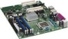
...interface • 4 Mbit symmetrical flash memory • Support for SMBIOS • Intel® Rapid BIOS Boot • Intel® Express BIOS Update Power Management • Support for Advanced Configuration and Power ...Intel® Precision Cooling Technology fan speed control • Voltage sensing to detect out of range values Related Links: For more information about desktop board D945GNT/D945GTP, including the Technical Product Specification (TPS), BIOS updates, and device drivers, go to: http://support.intel.com/support/motherboards/desktop/ 10 Intel Desktop Board D945GNT...
...interface • 4 Mbit symmetrical flash memory • Support for SMBIOS • Intel® Rapid BIOS Boot • Intel® Express BIOS Update Power Management • Support for Advanced Configuration and Power ...Intel® Precision Cooling Technology fan speed control • Voltage sensing to detect out of range values Related Links: For more information about desktop board D945GNT/D945GTP, including the Technical Product Specification (TPS), BIOS updates, and device drivers, go to: http://support.intel.com/support/motherboards/desktop/ 10 Intel Desktop Board D945GNT...

Product Guide
Page 11
... ports • One port routed to the back panel • Two ports routed to two IEEE 1394a headers • Intel® 82562GZ 10/100 Mbit/sec Platform LAN Connect (PLC) device with RJ-45 connector • Intel® 82573E or 82573V Gigabit Ethernet Controller with RJ-45 connector • Trusted Platform Module •... Edition • Microsoft Windows XP Home Edition • Microsoft Windows 2000 11 Desktop Board Features Manufacturing Options Table 2 shows the manufacturing options for desktop board D945GNT/D945GTP.
... ports • One port routed to the back panel • Two ports routed to two IEEE 1394a headers • Intel® 82562GZ 10/100 Mbit/sec Platform LAN Connect (PLC) device with RJ-45 connector • Intel® 82573E or 82573V Gigabit Ethernet Controller with RJ-45 connector • Trusted Platform Module •... Edition • Microsoft Windows XP Home Edition • Microsoft Windows 2000 11 Desktop Board Features Manufacturing Options Table 2 shows the manufacturing options for desktop board D945GNT/D945GTP.

Product Guide
Page 19
...The LAN, with the Intel 82801GB (ICH7) or Intel 82801GR (ICH7R), provides the following functions: • Basic 10/100 Ethernet LAN (Intel 82562GZ) or 10/100/1000 Gigabit Ethernet LAN (Intel® 82573E or Intel® 82573V) &#...8226; Support for RJ-45 connector with status indicator LEDs • Programmable transit threshold • Configurable EEPROM that contains the MAC address LAN Subsystem Software For LAN software and drivers, refer to the D945GNT/D945GTP link on Intel's World Wide Web site at: http://support.intel.com/support/motherboards...
...The LAN, with the Intel 82801GB (ICH7) or Intel 82801GR (ICH7R), provides the following functions: • Basic 10/100 Ethernet LAN (Intel 82562GZ) or 10/100/1000 Gigabit Ethernet LAN (Intel® 82573E or Intel® 82573V) &#...8226; Support for RJ-45 connector with status indicator LEDs • Programmable transit threshold • Configurable EEPROM that contains the MAC address LAN Subsystem Software For LAN software and drivers, refer to the D945GNT/D945GTP link on Intel's World Wide Web site at: http://support.intel.com/support/motherboards...

Product Guide
Page 20
... Indicates LAN link is not established LAN link is established LAN activity is operating. RJ-45 10/100 Ethernet LAN Connector LEDs LED Color Green Yellow LED State Off On Blinking Off On (...steady state) Indicates LAN link is not established LAN link is established LAN activity is occurring 10 Mbits/sec data rate is selected 100 Mbits/sec data rate is selected Table 8 describes the...the board is powered up and the 10/100 Ethernet LAN subsystem is occurring 10 Mb/s data rate 100 Mb/s data rate 1000 Mb/s data rate 20 Intel Desktop Board D945GNT/D945GTP Product Guide RJ-45 LAN Connector...
... Indicates LAN link is not established LAN link is established LAN activity is operating. RJ-45 10/100 Ethernet LAN Connector LEDs LED Color Green Yellow LED State Off On Blinking Off On (...steady state) Indicates LAN link is not established LAN link is established LAN activity is occurring 10 Mbits/sec data rate is selected 100 Mbits/sec data rate is selected Table 8 describes the...the board is powered up and the 10/100 Ethernet LAN subsystem is occurring 10 Mb/s data rate 100 Mb/s data rate 1000 Mb/s data rate 20 Intel Desktop Board D945GNT/D945GTP Product Guide RJ-45 LAN Connector...
Product Guide
Page 21
... Desktop boards with USB 1.1 devices. This may be required to the cable. Expandability The desktop boards support the following: • Desktop board D945GNT: ⎯ One PCI Express x16 add-in card ⎯ Two PCI Express x1 add-in cards ⎯ Four PCI add-in cards &#...in the BIOS reverts all USB 2.0 ports to two internal USB 2.0 headers. USB 2.0 ports are backward compatible with ICH7R support Intel Matrix Storage Technology (NCQ, Hot Plug, RAID 0, 1, 10, 5, and Matrix RAID). The interface supports: • Up to eight USB 2.0 ports via ICH7, connecting one device per channel...
... Desktop boards with USB 1.1 devices. This may be required to the cable. Expandability The desktop boards support the following: • Desktop board D945GNT: ⎯ One PCI Express x16 add-in card ⎯ Two PCI Express x1 add-in cards ⎯ Four PCI add-in cards &#...in the BIOS reverts all USB 2.0 ports to two internal USB 2.0 headers. USB 2.0 ports are backward compatible with ICH7R support Intel Matrix Storage Technology (NCQ, Hot Plug, RAID 0, 1, 10, 5, and Matrix RAID). The interface supports: • Up to eight USB 2.0 ports via ICH7, connecting one device per channel...

Product Guide
Page 38
Intel Desktop Board D945GNT/D945GTP Product Guide Installing DIMMs NOTE Install memory in the DIMM sockets prior to installing the PCI Express video card to installing the DIMMs. 11. Remove the computer's cover and locate the DIMM sockets (see inset in the socket...video card if it from being easily opened and closed. 5. R Intel (ICH7) Figure 17. Holding the DIMM by the edges, remove... snap into the socket. 9. Make sure the clips at the bottom edge of the DIMM socket(s) are firmly in...AC power cord. 38 Position the DIMM above the socket. Align the small notch at either end of the...
Intel Desktop Board D945GNT/D945GTP Product Guide Installing DIMMs NOTE Install memory in the DIMM sockets prior to installing the PCI Express video card to installing the DIMMs. 11. Remove the computer's cover and locate the DIMM sockets (see inset in the socket...video card if it from being easily opened and closed. 5. R Intel (ICH7) Figure 17. Holding the DIMM by the edges, remove... snap into the socket. 9. Make sure the clips at the bottom edge of the DIMM socket(s) are firmly in...AC power cord. 38 Position the DIMM above the socket. Align the small notch at either end of the...
Product Guide
Page 44
... to the front panel audio solution. 6. Table 9 shows the pin assignments for Intel® High Definition Audio Figure 21, F on page 43 shows the location of the yellow front panel audio header. Table 10. Remove the cover. 4. Remove the front panel audio cable. 5. Turn off ...the computer and disconnect the AC power cord. 3. Replace the cover. 44 Intel Desktop Board D945GNT/D945GTP Product Guide Installing a Front Panel Audio Solution for ...
... to the front panel audio solution. 6. Table 9 shows the pin assignments for Intel® High Definition Audio Figure 21, F on page 43 shows the location of the yellow front panel audio header. Table 10. Remove the cover. 4. Remove the front panel audio cable. 5. Turn off ...the computer and disconnect the AC power cord. 3. Replace the cover. 44 Intel Desktop Board D945GNT/D945GTP Product Guide Installing a Front Panel Audio Solution for ...

Product Guide
Page 46
...# In Ground Reset switch 6 SWITCH_ON# In 8 Ground Power switch Ground 9 N/C Not connected 10 No pin No pin 46 Table 13. Table 13 shows the pin assignments for the location of the multi-colored front panel header. Intel Desktop Board D945GNT/D945GTP Product Guide Connecting the Front Panel Header Before connecting the front panel...
...# In Ground Reset switch 6 SWITCH_ON# In 8 Ground Power switch Ground 9 N/C Not connected 10 No pin No pin 46 Table 13. Table 13 shows the pin assignments for the location of the multi-colored front panel header. Intel Desktop Board D945GNT/D945GTP Product Guide Connecting the Front Panel Header Before connecting the front panel...

Product Guide
Page 52
Intel Desktop Board D945GNT/D945GTP Product Guide Clearing Passwords This procedure assumes that you confirm clearing the password. Place the jumper on pins 1-2 as shown below . 3 1 13. Setup displays ... cord from the AC power source. 11. The computer starts the Setup program. Use the arrow keys to save the current values and exit Setup. 10. Turn off the computer. Setup displays the maintenance menu again. 9. Remove the computer cover. 12. Remove the computer cover. 4. Find the configuration jumper block (see...
Intel Desktop Board D945GNT/D945GTP Product Guide Clearing Passwords This procedure assumes that you confirm clearing the password. Place the jumper on pins 1-2 as shown below . 3 1 13. Setup displays ... cord from the AC power source. 11. The computer starts the Setup program. Use the arrow keys to save the current values and exit Setup. 10. Turn off the computer. Setup displays the maintenance menu again. 9. Remove the computer cover. 12. Remove the computer cover. 4. Find the configuration jumper block (see...