Product Guide
Page 6
...* XP or 2000 and SATA Hard Drive(s) Configuring the BIOS for RAID (Intel® Matrix Storage Technology) - Intel Desktop Board D945GCZ Product Guide Installing and Removing the Desktop Board 29 Installing and Removing a Processor 30 Installing a Processor 30 Installing the Processor Fan Heat Sink 33 Connecting the Processor Fan Heat Sink Cable 33 Removing the Processor 33 Installing and Removing Memory 34 Installing...
...* XP or 2000 and SATA Hard Drive(s) Configuring the BIOS for RAID (Intel® Matrix Storage Technology) - Intel Desktop Board D945GCZ Product Guide Installing and Removing the Desktop Board 29 Installing and Removing a Processor 30 Installing a Processor 30 Installing the Processor Fan Heat Sink 33 Connecting the Processor Fan Heat Sink Cable 33 Removing the Processor 33 Installing and Removing Memory 34 Installing...

Product Guide
Page 7
... Key ...55 vii Contents Product Ecology Statements 65 Lead-Free Desktop Board 68 EMC Regulations ...69 Product Certification Markings (Board Level 70 Figures 1. Installing a DIMM ...36 17. LAN Port LED Locations 18 3. Connecting the Processor Fan Heat Sink Cable to the Processor Fan Connector ........33 13. Desktop Board D945GCZ Components 12 2. Desktop Board D945GCZ Mounting Screw Hole Locations 29 6. Dual Configuration Example 1 34...
... Key ...55 vii Contents Product Ecology Statements 65 Lead-Free Desktop Board 68 EMC Regulations ...69 Product Certification Markings (Board Level 70 Figures 1. Installing a DIMM ...36 17. LAN Port LED Locations 18 3. Connecting the Processor Fan Heat Sink Cable to the Processor Fan Connector ........33 13. Desktop Board D945GCZ Components 12 2. Desktop Board D945GCZ Mounting Screw Hole Locations 29 6. Dual Configuration Example 1 34...

Product Guide
Page 21
... Plug and Play functions of ACPI with the desktop board requires an operating system that processor fan speed control remain enabled (default BIOS setting) when using the processor fan heat-sink included with Intel® boxed processors. The chassis fan speed control feature should be disabled independently through the desktop board BIOS. System fan noise may be reduced by operating controlled...
... Plug and Play functions of ACPI with the desktop board requires an operating system that processor fan speed control remain enabled (default BIOS setting) when using the processor fan heat-sink included with Intel® boxed processors. The chassis fan speed control feature should be disabled independently through the desktop board BIOS. System fan noise may be reduced by operating controlled...
Product Guide
Page 33
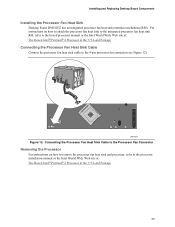
... Connecting the Processor Fan Heat Sink Cable to the Processor Fan Connector Removing the Processor For instructions on how to attach the processor fan heat sink to the integrated processor fan heat sink RM, refer to the 4-pin processor fan connector (see Figure 12). OM17637 Figure 12. Installing and Replacing Desktop Board Components Installing the Processor Fan Heat Sink Desktop board D945GCZ has an integrated processor fan heat sink retention mechanism (RM...
... Connecting the Processor Fan Heat Sink Cable to the Processor Fan Connector Removing the Processor For instructions on how to attach the processor fan heat sink to the integrated processor fan heat sink RM, refer to the 4-pin processor fan connector (see Figure 12). OM17637 Figure 12. Installing and Replacing Desktop Board Components Installing the Processor Fan Heat Sink Desktop board D945GCZ has an integrated processor fan heat sink retention mechanism (RM...

Product Guide
Page 45
Installing and Replacing Desktop Board Components Connecting Fan and Power Cables Connecting Fan Cables Figure 22 shows the location of Fan Headers OM17642 45 Connect the processor's fan heat sink cable to the 3-pin fan headers. 43 2 1 A 43 2 1 B OR 3 21 A 3 21 B Figure 22. Location of the fan headers. Connect chassis fan cables to the 4-pin processor fan header on the board.
Installing and Replacing Desktop Board Components Connecting Fan and Power Cables Connecting Fan Cables Figure 22 shows the location of Fan Headers OM17642 45 Connect the processor's fan heat sink cable to the 3-pin fan headers. 43 2 1 A 43 2 1 B OR 3 21 A 3 21 B Figure 22. Location of the fan headers. Connect chassis fan cables to the 4-pin processor fan header on the board.


