Product Guide
Page 2
... Guide Second release of the Intel® Desktop Board D945GCLF2D Product Guide Date November 2008 December 2008 If an FCC declaration of conformity marking is present on request. Contact your local Intel sales office or your product order. Intel, the Intel logo, and Intel Atom are available on the board, the following two conditions: (1) this device may cause the product to comply with Part...
... Guide Second release of the Intel® Desktop Board D945GCLF2D Product Guide Date November 2008 December 2008 If an FCC declaration of conformity marking is present on request. Contact your local Intel sales office or your product order. Intel, the Intel logo, and Intel Atom are available on the board, the following two conditions: (1) this device may cause the product to comply with Part...
Product Guide
Page 3
... attention to update the BIOS A BIOS Error Messages: information about BIOS error messages and beep codes B Regulatory Compliance: safety and EMC regulations and product certifications Conventions The following conventions are used in this manual: CAUTION Cautions warn the user about board layout, component installation, and regulatory requirements for installation in this Product Guide are evaluated as Information Technology Equipment (I.T.E.) for use in personal computers (PC) for Intel® Desktop Board D945GCLF2D. Document...
... attention to update the BIOS A BIOS Error Messages: information about BIOS error messages and beep codes B Regulatory Compliance: safety and EMC regulations and product certifications Conventions The following conventions are used in this manual: CAUTION Cautions warn the user about board layout, component installation, and regulatory requirements for installation in this Product Guide are evaluated as Information Technology Equipment (I.T.E.) for use in personal computers (PC) for Intel® Desktop Board D945GCLF2D. Document...
Product Guide
Page 5
.../Output (I/O) Controller 14 LAN Subsystem 15 LAN Subsystem Software 15 LAN Status LEDs 15 Hi-Speed USB 2.0 Support 16 Enhanced IDE Interface 16 Serial ATA...16 Expandability...16 BIOS ...17 IDE Auto Configuration 17 PCI Auto Configuration 17 Security Passwords 17 Power Management Features 18 ACPI ...18 Hardware Support 18 Power Connectors 18 Fan Headers 18 +5 V Standby Power Indicator LED 18 LAN Wake Capabilities 19 Wake from USB 19 Wake from PS/2 Keyboard/Mouse 20 PME# Wakeup Support 20 Battery ...20 Real-Time Clock 20 2 Installing and Replacing Desktop Board Components...
.../Output (I/O) Controller 14 LAN Subsystem 15 LAN Subsystem Software 15 LAN Status LEDs 15 Hi-Speed USB 2.0 Support 16 Enhanced IDE Interface 16 Serial ATA...16 Expandability...16 BIOS ...17 IDE Auto Configuration 17 PCI Auto Configuration 17 Security Passwords 17 Power Management Features 18 ACPI ...18 Hardware Support 18 Power Connectors 18 Fan Headers 18 +5 V Standby Power Indicator LED 18 LAN Wake Capabilities 19 Wake from USB 19 Wake from PS/2 Keyboard/Mouse 20 PME# Wakeup Support 20 Battery ...20 Real-Time Clock 20 2 Installing and Replacing Desktop Board Components...
Product Guide
Page 6
Intel Desktop Board D945GCLF2D Product Guide Connecting a Chassis Fan 33 Connecting Power Supply Cables 34 Setting the BIOS Configuration Jumper 35 Clearing Passwords 36 Replacing the Battery 37 3 Updating the BIOS Updating the BIOS with the Intel® Express BIOS Update Utility 43 Updating the BIOS with the Iflash Memory Update Utility 43 Obtaining the BIOS Update File 43 Updating the BIOS with the Iflash Memory Update Utility 44 Recovering the BIOS 44 A BIOS Error Messages BIOS Front-panel Power LED Blink Codes 45 BIOS Beep Codes 45 BIOS Error Messages 46 B Regulatory ...
Intel Desktop Board D945GCLF2D Product Guide Connecting a Chassis Fan 33 Connecting Power Supply Cables 34 Setting the BIOS Configuration Jumper 35 Clearing Passwords 36 Replacing the Battery 37 3 Updating the BIOS Updating the BIOS with the Intel® Express BIOS Update Utility 43 Updating the BIOS with the Iflash Memory Update Utility 43 Obtaining the BIOS Update File 43 Updating the BIOS with the Iflash Memory Update Utility 44 Recovering the BIOS 44 A BIOS Error Messages BIOS Front-panel Power LED Blink Codes 45 BIOS Beep Codes 45 BIOS Error Messages 46 B Regulatory ...
Product Guide
Page 7
... 1. Location of the Chassis Fan Header 33 13. Connecting the Serial ATA Cable 29 11. Internal Headers 30 12. Removing the Battery 41 16. BIOS Front-panel Power LED Blink Codes 45 10. Use DDR2 DIMMs 25 8. Intel Desktop Board D945GCLF2D China RoHS Material Self Declaration Table.......54 Tables 1. EMC Regulations 55 16. Installing the I/O Shield 23 6. Feature Summary 9 2. S/PDIF Connector Signal Names 31 6. Jumper Settings for HD Audio 31 5. Safety Standards 47 13. Lead-Free Second...
... 1. Location of the Chassis Fan Header 33 13. Connecting the Serial ATA Cable 29 11. Internal Headers 30 12. Removing the Battery 41 16. BIOS Front-panel Power LED Blink Codes 45 10. Use DDR2 DIMMs 25 8. Intel Desktop Board D945GCLF2D China RoHS Material Self Declaration Table.......54 Tables 1. EMC Regulations 55 16. Installing the I/O Shield 23 6. Feature Summary 9 2. S/PDIF Connector Signal Names 31 6. Jumper Settings for HD Audio 31 5. Safety Standards 47 13. Lead-Free Second...
Product Guide
Page 9
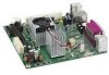
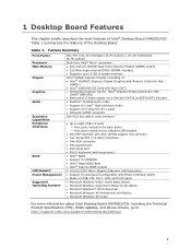
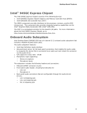
... about Intel Desktop Board D945GCLF2D, including the Technical Product Specification (TPS), BIOS updates, and device drivers, go to 2 GB of system memory Intel® 945GC Express Chipset consisting of the Desktop Board. Feature Summary Form Factor Processor Main Memory Chipset Graphics Audio Expansion Capabilities Peripheral Interfaces BIOS LAN Support Power Management Supported Operating Systems Mini-ITX (171.45 millimeters [6.75 inches] x 171.45 millimeters [6.75 inches]) Dual-Core Intel® Atom™ processor • One 240-pin SDRAM Dual Inline Memory Module (DIMM) socket •...
... about Intel Desktop Board D945GCLF2D, including the Technical Product Specification (TPS), BIOS updates, and device drivers, go to 2 GB of system memory Intel® 945GC Express Chipset consisting of the Desktop Board. Feature Summary Form Factor Processor Main Memory Chipset Graphics Audio Expansion Capabilities Peripheral Interfaces BIOS LAN Support Power Management Supported Operating Systems Mini-ITX (171.45 millimeters [6.75 inches] x 171.45 millimeters [6.75 inches]) Dual-Core Intel® Atom™ processor • One 240-pin SDRAM Dual Inline Memory Module (DIMM) socket •...
Product Guide
Page 12
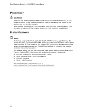
... memory controller for normal operation. Main Memory NOTE To be fully compliant with all applicable Intel® SDRAM memory specifications, the board should be populated with gold-plated contacts. Intel Desktop Board D945GCLF2D Product Guide Processor CAUTION Failure to use an appropriate power supply and/or not connecting the 12 V (2 x 2) power connector to the Desktop Board may result in damage to http://support.intel.com/support/motherboards/desktop/. 12 The Desktop Board has one 240-pin Double Data Rate 2 (DDR2) SDRAM Dual...
... memory controller for normal operation. Main Memory NOTE To be fully compliant with all applicable Intel® SDRAM memory specifications, the board should be populated with gold-plated contacts. Intel Desktop Board D945GCLF2D Product Guide Processor CAUTION Failure to use an appropriate power supply and/or not connecting the 12 V (2 x 2) power connector to the Desktop Board may result in damage to http://support.intel.com/support/motherboards/desktop/. 12 The Desktop Board has one 240-pin Double Data Rate 2 (DDR2) SDRAM Dual...
Product Guide
Page 13
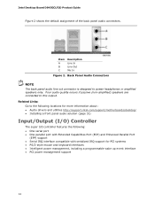
... The Intel 945GC Express Chipset consists of the following headers and connectors: • Onboard S/PDIF connector (3-pin) • Front panel audio header, including functionality for the back panel connectors, that enables the audio codec to recognize the device that is a centralized controller for the board's I /O Controller Hub (ICH7) The GMCH component provides interfaces to the processor, memory, and the DMI interconnect. Onboard Audio Subsystem Intel Desktop Board D945GCLF2D has a 6-channel (5.1) onboard audio subsystem that are configurable through the audio device drivers...
... The Intel 945GC Express Chipset consists of the following headers and connectors: • Onboard S/PDIF connector (3-pin) • Front panel audio header, including functionality for the back panel connectors, that enables the audio codec to recognize the device that is a centralized controller for the board's I /O Controller Hub (ICH7) The GMCH component provides interfaces to the processor, memory, and the DMI interconnect. Onboard Audio Subsystem Intel Desktop Board D945GCLF2D has a 6-channel (5.1) onboard audio subsystem that are configurable through the audio device drivers...
Product Guide
Page 14
....intel.com/support/motherboards/desktop/ • Installing a front panel audio solution (page 31) Input/Output (I/O) Controller The super I/O controller features the following: • One serial port • One parallel port with Extended Capabilities Port (ECP) and Enhanced Parallel Port (EPP) support • Serial IRQ interface compatible with serialized IRQ support for PCI systems • PS/2-style mouse and keyboard interfaces • Intelligent power management, including a programmable wake up event interface • PCI power management support 14 Intel Desktop Board D945GCLF2D...
....intel.com/support/motherboards/desktop/ • Installing a front panel audio solution (page 31) Input/Output (I/O) Controller The super I/O controller features the following: • One serial port • One parallel port with Extended Capabilities Port (ECP) and Enhanced Parallel Port (EPP) support • Serial IRQ interface compatible with serialized IRQ support for PCI systems • PS/2-style mouse and keyboard interfaces • Intelligent power management, including a programmable wake up event interface • PCI power management support 14 Intel Desktop Board D945GCLF2D...
Product Guide
Page 15
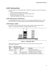
... Table 3. Desktop Board Features LAN Subsystem The LAN, based on the RealTek RTL8111C Ethernet Controller, provides the following functions: • 10/100/1000 Mb/s Gigabit Ethernet LAN • Support for RJ-45 connector with status indicator LEDs • Programmable transit threshold • Configurable EEPROM that contains the MAC address LAN Subsystem Software For LAN software and drivers, refer to the Intel Desktop D945GCLF2D link on the back panel (see...
... Table 3. Desktop Board Features LAN Subsystem The LAN, based on the RealTek RTL8111C Ethernet Controller, provides the following functions: • 10/100/1000 Mb/s Gigabit Ethernet LAN • Support for RJ-45 connector with status indicator LEDs • Programmable transit threshold • Configurable EEPROM that contains the MAC address LAN Subsystem Software For LAN software and drivers, refer to the Intel Desktop D945GCLF2D link on the back panel (see...
Product Guide
Page 16
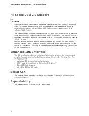
... panel and four ports routed to the cable. Enhanced IDE Interface The IDE interface handles the exchange of information between the processor and peripheral devices such as CD-ROM or DVD drives) • Older PIO Mode devices • Ultra DMA-33/66/100 modes Serial ATA The Desktop Board supports two Serial ATA channels (3.0 Gb/s), connecting one PCI add-in the BIOS reverts all USB 2.0 ports to USB 1.1 operation. Expandability The Desktop Board supports one device per channel. The interface supports...
... panel and four ports routed to the cable. Enhanced IDE Interface The IDE interface handles the exchange of information between the processor and peripheral devices such as CD-ROM or DVD drives) • Older PIO Mode devices • Ultra DMA-33/66/100 modes Serial ATA The Desktop Board supports two Serial ATA channels (3.0 Gb/s), connecting one PCI add-in the BIOS reverts all USB 2.0 ports to USB 1.1 operation. Expandability The Desktop Board supports one device per channel. The interface supports...
Product Guide
Page 17
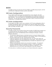
... For instructions on resetting the password, see Clearing Passwords on whether the supervisor or user password was entered. • Setting a user password restricts who can override the auto-configuration options by specifying manual configuration in card. Desktop Board Features BIOS The BIOS provides the Power-On Self-Test (POST), the BIOS Setup program, the PCI and IDE auto-configuration utilities, and the video BIOS. You do not need to run the BIOS Setup program after you install a PCI add-in card in card. You do not need to boot...
... For instructions on resetting the password, see Clearing Passwords on whether the supervisor or user password was entered. • Setting a user password restricts who can override the auto-configuration options by specifying manual configuration in card. Desktop Board Features BIOS The BIOS provides the Power-On Self-Test (POST), the BIOS Setup program, the PCI and IDE auto-configuration utilities, and the video BIOS. You do not need to run the BIOS Setup program after you install a PCI add-in card in card. You do not need to boot...

Product Guide
Page 18
...; Advanced Configuration and Power Interface (ACPI) • Hardware support: ― Power connectors ― Fan headers ― +5 V standby power indicator LED ― LAN Wake capabilities ― Wake from USB ― Wake from PS/2 keyboard/mouse ― PME# wakeup support ACPI ACPI gives the operating system direct control over the power management and Plug and Play functions of the chassis fan header. +5 V Standby Power Indicator LED CAUTION If the AC power has been switched off . 18 Hardware Support Power Connectors The Desktop Board has two power connectors. Failure to...
...; Advanced Configuration and Power Interface (ACPI) • Hardware support: ― Power connectors ― Fan headers ― +5 V standby power indicator LED ― LAN Wake capabilities ― Wake from USB ― Wake from PS/2 keyboard/mouse ― PME# wakeup support ACPI ACPI gives the operating system direct control over the power management and Plug and Play functions of the chassis fan header. +5 V Standby Power Indicator LED CAUTION If the AC power has been switched off . 18 Hardware Support Power Connectors The Desktop Board has two power connectors. Failure to...
Product Guide
Page 19
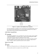
...* frame, it asserts a wake-up the computer. USB bus activity wakes the computer from USB requires the use of the computer through a network. Wake from USB NOTE Wake from an ACPI S3 state. 19 Location of the Standby Power Indicator For more information on the Intel Desktop D945GCLF2D web page at http://support.intel.com/support/motherboards/desktop/ LAN Wake Capabilities CAUTION For LAN wake capabilities, the 5 V standby line for the Desktop Board, refer to provide adequate...
...* frame, it asserts a wake-up the computer. USB bus activity wakes the computer from USB requires the use of the computer through a network. Wake from USB NOTE Wake from an ACPI S3 state. 19 Location of the Standby Power Indicator For more information on the Intel Desktop D945GCLF2D web page at http://support.intel.com/support/motherboards/desktop/ LAN Wake Capabilities CAUTION For LAN wake capabilities, the 5 V standby line for the Desktop Board, refer to provide adequate...
Product Guide
Page 21
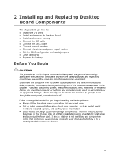
... to a metal part of the procedures described in this chapter only at an ESD workstation using and modifying electronic equipment. 2 Installing and Replacing Desktop Board Components This chapter tells you how to: • Install the I/O shield • Install and remove the Desktop Board • Install and remove memory • Connect the IDE cable • Connect the SATA cable • Connect internal headers • Connect chassis fan and power supply cables • Set the BIOS configuration and audio jumpers • Clear passwords • Replace the battery Before You Begin...
... to a metal part of the procedures described in this chapter only at an ESD workstation using and modifying electronic equipment. 2 Installing and Replacing Desktop Board Components This chapter tells you how to: • Install the I/O shield • Install and remove the Desktop Board • Install and remove memory • Connect the IDE cable • Connect the SATA cable • Connect internal headers • Connect chassis fan and power supply cables • Set the BIOS configuration and audio jumpers • Clear passwords • Replace the battery Before You Begin...
Product Guide
Page 35
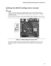
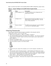
BIOS Configuration Jumper Block The three-pin BIOS jumper block enables all board configuration to be done in unreliable computer operation. Table 8 shows the jumper settings for the Setup program modes. 35 Figure 14 shows the location of the Desktop Board's BIOS configuration jumper block. Installing and Replacing Desktop Board Components Setting the BIOS Configuration Jumper NOTE Always turn off the power and unplug the power cord from the computer before changing a jumper. Moving the jumper with the power on may result in the BIOS Setup program. Figure 14.
BIOS Configuration Jumper Block The three-pin BIOS jumper block enables all board configuration to be done in unreliable computer operation. Table 8 shows the jumper settings for the Setup program modes. 35 Figure 14 shows the location of the Desktop Board's BIOS configuration jumper block. Installing and Replacing Desktop Board Components Setting the BIOS Configuration Jumper NOTE Always turn off the power and unplug the power cord from the computer before changing a jumper. Moving the jumper with the power on may result in the BIOS Setup program. Figure 14.
Product Guide
Page 36
... event of the Desktop Board's BIOS configuration jumper block. Place the jumper on the computer, and allow it to normal mode. 1. The computer starts the Setup program. Press and Setup displays a pop-up screen requesting that the board is set to boot. 7. Turn off all peripheral devices connected to select Clear Passwords. Recovery (None) The BIOS recovers data from a recovery diskette in the computer, turn on pins 2-3 as shown below. 6. Turn off the computer. Remove the computer...
... event of the Desktop Board's BIOS configuration jumper block. Place the jumper on the computer, and allow it to normal mode. 1. The computer starts the Setup program. Press and Setup displays a pop-up screen requesting that the board is set to boot. 7. Turn off all peripheral devices connected to select Clear Passwords. Recovery (None) The BIOS recovers data from a recovery diskette in the computer, turn on pins 2-3 as shown below. 6. Turn off the computer. Remove the computer...
Product Guide
Page 43
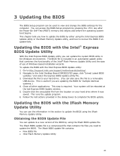
... key after the Power-On Self-Test (POST) memory test begins and before the operating system boot begins. You can update to a removable USB device. Go to the Intel Desktop Board D945GCLF2D page, click "[view] Latest BIOS updates," and select the Express BIOS Update utility file. 3. Follow the instructions provided in the Windows environment. Navigate to http://support.intel.com/support/motherboards/desktop/. 2. The Iflash BIOS update file is included in this file to a new version of the BIOS by either using the Iflash BIOS update file. 3 Updating...
... key after the Power-On Self-Test (POST) memory test begins and before the operating system boot begins. You can update to a removable USB device. Go to the Intel Desktop Board D945GCLF2D page, click "[view] Latest BIOS updates," and select the Express BIOS Update utility file. 3. Follow the instructions provided in the Windows environment. Navigate to http://support.intel.com/support/motherboards/desktop/. 2. The Iflash BIOS update file is included in this file to a new version of the BIOS by either using the Iflash BIOS update file. 3 Updating...
Product Guide
Page 44
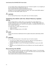
.... 2. Configure the BIOS or use the F10 key option during POST to boot to http://support.intel.com/support/motherboards/desktop/. 44 For more information about recovering the BIOS for Intel Desktop Board D945GCLF2D, go to the USB device. 3. The Iflash BIOS update files can update the system BIOS from the USB device and manually update the BIOS. Uncompress the BIOS update file and copy the .BIO file and IFLASH.EXE to the Intel Desktop D945GCLF2D page, click "[view] Latest BIOS updates," and select the Iflash BIOS Update utility file. Navigate to a bootable USB flash drive...
.... 2. Configure the BIOS or use the F10 key option during POST to boot to http://support.intel.com/support/motherboards/desktop/. 44 For more information about recovering the BIOS for Intel Desktop Board D945GCLF2D, go to the USB device. 3. The Iflash BIOS update files can update the system BIOS from the USB device and manually update the BIOS. Uncompress the BIOS update file and copy the .BIO file and IFLASH.EXE to the Intel Desktop D945GCLF2D page, click "[view] Latest BIOS updates," and select the Iflash BIOS Update utility file. Navigate to a bootable USB flash drive...
Product Guide
Page 45
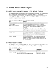
... error occurs during POST, the BIOS causes the front-panel power LED to blink an error message describing the problem (see Figure 2, B on -off blink pattern; BIOS Front-panel Power LED Blink Codes Type Processor initialization complete POST complete BIOS update in Table 10. pattern repeats until 16th on -off blink pattern; For example, the LED is on when the system is complete. BIOS Beep Codes Type Pattern Memory error Three long beeps Thermal warning Four alternating beeps: High...
... error occurs during POST, the BIOS causes the front-panel power LED to blink an error message describing the problem (see Figure 2, B on -off blink pattern; BIOS Front-panel Power LED Blink Codes Type Processor initialization complete POST complete BIOS update in Table 10. pattern repeats until 16th on -off blink pattern; For example, the LED is on when the system is complete. BIOS Beep Codes Type Pattern Memory error Three long beeps Thermal warning Four alternating beeps: High...


