

Product Specification
Page 7
... Monitoring for 8-Channel (7.1) Audio Subsystem .... 32 11. 8-channel (7.1) Audio Subsystem Block Diagram 33 12. Location of BIOS Features 3.1 Introduction ...95 3.2 BIOS Flash Memory Organization 96 3.3 Resource Configuration 96 3.3.1 PCI Autoconfiguration 96 3.3.2 PCI IDE Support 96 3.4 System Management BIOS (SMBIOS 97 3.5 Legacy USB Support...97 3.6 BIOS Updates ...98 3.6.1 Language Support 98 3.6.2 Custom Splash Screen 98 3.7 Boot Options ...99 3.7.1 CD-ROM Boot 99 3.7.2 Network Boot 99 3.7.3 Booting Without Attached Devices 99 3.7.4 Changing the Default Boot Device During...
... Monitoring for 8-Channel (7.1) Audio Subsystem .... 32 11. 8-channel (7.1) Audio Subsystem Block Diagram 33 12. Location of BIOS Features 3.1 Introduction ...95 3.2 BIOS Flash Memory Organization 96 3.3 Resource Configuration 96 3.3.1 PCI Autoconfiguration 96 3.3.2 PCI IDE Support 96 3.4 System Management BIOS (SMBIOS 97 3.5 Legacy USB Support...97 3.6 BIOS Updates ...98 3.6.1 Language Support 98 3.6.2 Custom Splash Screen 98 3.7 Boot Options ...99 3.7.1 CD-ROM Boot 99 3.7.2 Network Boot 99 3.7.3 Booting Without Attached Devices 99 3.7.4 Changing the Default Boot Device During...
Product Specification
Page 8
.... Processor Fan Connector and Auxiliary Rear Fan Connector 72 25. Chassis Intrusion Connector 73 26. Main Power Connector 75 30. Connection Diagram for Boards with the 8-Channel (7.1) Audio Subsystem 83 30. Location of Pressing the Power Switch 41 9. Feature Summary ...12 3. Wake-up Devices and Events 43 11. Back Panel Connectors Shown in Figure 22 71 21. Back Panel Connectors Shown in Figure 21 69 20. Serial ATA Connectors 73 28. Front Panel Connector 76 34. Localized High Temperature Zones...
.... Processor Fan Connector and Auxiliary Rear Fan Connector 72 25. Chassis Intrusion Connector 73 26. Main Power Connector 75 30. Connection Diagram for Boards with the 8-Channel (7.1) Audio Subsystem 83 30. Location of Pressing the Power Switch 41 9. Feature Summary ...12 3. Wake-up Devices and Events 43 11. Back Panel Connectors Shown in Figure 22 71 21. Back Panel Connectors Shown in Figure 21 69 20. Serial ATA Connectors 73 28. Front Panel Connector 76 34. Localized High Temperature Zones...
Product Specification
Page 11
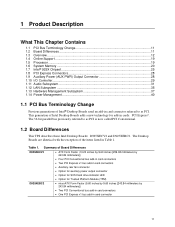
... Contains 1.1 PCI Bus Terminology Change 11 1.2 Board Differences ...11 1.3 Overview ...12 1.4 Online Support ...19 1.5 Processor ...19 1.6 System Memory ...20 1.7 Intel® 925X Chipset...25 1.8 PCI Express Connectors 28 1.9 Auxiliary Power (AUX PWR) Output Connector 28 1.10 I/O Controller...29 1.11 Audio Subsystem ...31 1.12 LAN Subsystem ...35 1.13 Hardware Management Subsystem 37 1.14 Power Management ...40 1.1 PCI Bus Terminology Change Previous generations of Intel® Desktop Boards used an add-in card connector referred to as PCI. This generation...
... Contains 1.1 PCI Bus Terminology Change 11 1.2 Board Differences ...11 1.3 Overview ...12 1.4 Online Support ...19 1.5 Processor ...19 1.6 System Memory ...20 1.7 Intel® 925X Chipset...25 1.8 PCI Express Connectors 28 1.9 Auxiliary Power (AUX PWR) Output Connector 28 1.10 I/O Controller...29 1.11 Audio Subsystem ...31 1.12 LAN Subsystem ...35 1.13 Hardware Management Subsystem 37 1.14 Power Management ...40 1.1 PCI Bus Terminology Change Previous generations of Intel® Desktop Boards used an add-in card connector referred to as PCI. This generation...
Product Specification
Page 13
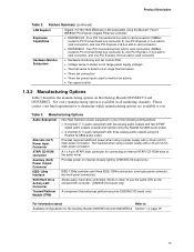
...options are available to monitor fan activity • Fan speed control 1.3.2 Manufacturing Options Table 3 describes the manufacturing options on the Desktop Boards D925XECV2 and D925XEBC2. ATAPI CD-ROM connector A 1 x 4-pin ATAPI-style connector for connecting an internal ATAPI CD-ROM drive to the audio mixer Auxiliary (AUX) Power Output Connector Provides power for internal chassis lighting (D925XECV2 board only) IEEE-1394a Interface SCSI Hard Drive Activity LED Connector IEEE-1394a controller and three IEEE-1394a connectors (one PCI Express x16 bus add-in all marketing channels...
...options are available to monitor fan activity • Fan speed control 1.3.2 Manufacturing Options Table 3 describes the manufacturing options on the Desktop Boards D925XECV2 and D925XEBC2. ATAPI CD-ROM connector A 1 x 4-pin ATAPI-style connector for connecting an internal ATAPI CD-ROM drive to the audio mixer Auxiliary (AUX) Power Output Connector Provides power for internal chassis lighting (D925XECV2 board only) IEEE-1394a Interface SCSI Hard Drive Activity LED Connector IEEE-1394a controller and three IEEE-1394a connectors (one PCI Express x16 bus add-in all marketing channels...

Product Specification
Page 15
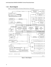
... PCI Express x16 bus add-in card connector Rear chassis fan connector Back panel connectors Alternate power connector +12V power connector (ATX12V) LGA775 processor socket Processor fan connector Intel 82925XE MCH DIMM Channel A sockets DIMM Channel B sockets I/O controller Power connector Diskette drive connector Parallel ATE IDE connector Battery Chassis intrusion connector BIOS Setup configuration jumper block 8 Mbit Firmware Hub (FWH) Front chassis fan connector Serial ATA connectors Auxiliary front panel power LED connector Front panel connector SCSI hard drive indicator LED (optional...
... PCI Express x16 bus add-in card connector Rear chassis fan connector Back panel connectors Alternate power connector +12V power connector (ATX12V) LGA775 processor socket Processor fan connector Intel 82925XE MCH DIMM Channel A sockets DIMM Channel B sockets I/O controller Power connector Diskette drive connector Parallel ATE IDE connector Battery Chassis intrusion connector BIOS Setup configuration jumper block 8 Mbit Firmware Hub (FWH) Front chassis fan connector Serial ATA connectors Auxiliary front panel power LED connector Front panel connector SCSI hard drive indicator LED (optional...
Product Specification
Page 18
... Controller LAN Connector USB Back Panel/Front Panel USB Ports LPC Bus I/O Controller LPC Bus Serial Ports Parallel Port PS/2 Mouse PS/2 Keyboard Diskette Drive Connector Intel 82801FR I/O Controller Hub (ICH6-R) 8 Mbit Firmware Hub (FWH) LPC Bus Intel 925XE Chipset TPM Component (Optional) Serial ATA IDE Interface Serial ATA IDE Connectors (4) High Definition Audio Link IEEE-1394a Connectors (Optional) PCI Bus Front Panel Retasking Jack A/E Front Panel Retasking Jack F PCI Bus PCI Slot 1 PCI Slot 2 PCI Slot 3 PCI Slot 4 SMBus D925XECV2 only Hardware Monitoring and Fan...
... Controller LAN Connector USB Back Panel/Front Panel USB Ports LPC Bus I/O Controller LPC Bus Serial Ports Parallel Port PS/2 Mouse PS/2 Keyboard Diskette Drive Connector Intel 82801FR I/O Controller Hub (ICH6-R) 8 Mbit Firmware Hub (FWH) LPC Bus Intel 925XE Chipset TPM Component (Optional) Serial ATA IDE Interface Serial ATA IDE Connectors (4) High Definition Audio Link IEEE-1394a Connectors (Optional) PCI Bus Front Panel Retasking Jack A/E Front Panel Retasking Jack F PCI Bus PCI Slot 1 PCI Slot 2 PCI Slot 3 PCI Slot 4 SMBus D925XECV2 only Hardware Monitoring and Fan...

Product Specification
Page 27
... Serial ATA RAID configuration Refer to http://developer.intel.com/design/motherbd/cv2/index.htm 1.7.2.5 SCSI Hard Drive Activity LED Connector (Optional) The SCSI hard drive activity LED connector is optional). Two physical drives, of identical size, can be created by using the Intel Application Accelerator (IAA) utility. 3. Two physical drives, of identical size, maintain duplicate sets of all information are required to the LED output of the add-in hard drive controller. Enable RAID Support in BIOS. 2. Install the IAA RAID driver...
... Serial ATA RAID configuration Refer to http://developer.intel.com/design/motherbd/cv2/index.htm 1.7.2.5 SCSI Hard Drive Activity LED Connector (Optional) The SCSI hard drive activity LED connector is optional). Two physical drives, of identical size, can be created by using the Intel Application Accelerator (IAA) utility. 3. Two physical drives, of identical size, maintain duplicate sets of all information are required to the LED output of the add-in hard drive controller. Enable RAID Support in BIOS. 2. Install the IAA RAID driver...

Product Specification
Page 51
... restore access to the Infineon Security Platform software and Wave Systems EMBASSY Trust Suite that contains the archive file is not present when a new key is available. 19. Follow the instructions and create and document the locations for both the archive and restoration key files. These documents and files should be updated after any password changes. 1.15.7 Recovery Procedures 1.15.7.1 Recovering from Hard Disk Failure Restore...
... restore access to the Infineon Security Platform software and Wave Systems EMBASSY Trust Suite that contains the archive file is not present when a new key is available. 19. Follow the instructions and create and document the locations for both the archive and restoration key files. These documents and files should be updated after any password changes. 1.15.7 Recovery Procedures 1.15.7.1 Recovering from Hard Disk Failure Restore...
Product Specification
Page 96
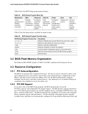
... and displays processor information Displays processor and memory configuration Configures advanced features available through the chipset Sets passwords and security features Power Boot Configures power management features and power supply controls Selects boot options Exit Saves or discards changes to configure the system. Intel Desktop Boards D925XECV2/D925XEBC2 Technical Product Specification Table 44 lists the BIOS Setup program menu features. Table 45. When a user turns on the system after adding a PCI card, the BIOS automatically configures interrupts, the I /O channel support...
... and displays processor information Displays processor and memory configuration Configures advanced features available through the chipset Sets passwords and security features Power Boot Configures power management features and power supply controls Selects boot options Exit Saves or discards changes to configure the system. Intel Desktop Boards D925XECV2/D925XEBC2 Technical Product Specification Table 44 lists the BIOS Setup program menu features. Table 45. When a user turns on the system after adding a PCI card, the BIOS automatically configures interrupts, the I /O channel support...
Product Specification
Page 97
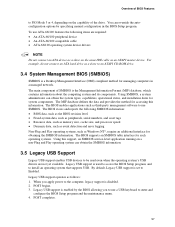
... compatible cable • ATA-66/100 operating system device drivers NOTE Do not connect an ATA device as a slave on the same IDE cable as a slave to the computer, legacy support is disabled. 2. The BIOS enables applications such as third-party management software to Enabled. When you to use a USB keyboard to install an operating system that supports USB. For example, do not connect an ATA hard drive as an ATAPI master device. POST begins. 3. The main...
... compatible cable • ATA-66/100 operating system device drivers NOTE Do not connect an ATA device as a slave on the same IDE cable as a slave to the computer, legacy support is disabled. 2. The BIOS enables applications such as third-party management software to Enabled. When you to use a USB keyboard to install an operating system that supports USB. For example, do not connect an ATA hard drive as an ATAPI master device. POST begins. 3. The main...
Product Specification
Page 100
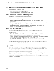
... minimize hard drive startup delays. • Select a CD-ROM drive with a fast initialization rate. Monitors and hard disk drives with minimum initialization times can influence POST execution time. • Eliminate unnecessary add-in the Drive Configuration Submenu of the BIOS Setup program). 100 Intel Desktop Boards D925XECV2/D925XEBC2 Technical Product Specification 3.8 Fast Booting Systems with Intel® Rapid BIOS Boot These factors affect system boot speed: • Selecting and configuring peripherals properly • Using an optimized BIOS...
... minimize hard drive startup delays. • Select a CD-ROM drive with a fast initialization rate. Monitors and hard disk drives with minimum initialization times can influence POST execution time. • Eliminate unnecessary add-in the Drive Configuration Submenu of the BIOS Setup program). 100 Intel Desktop Boards D925XECV2/D925XEBC2 Technical Product Specification 3.8 Fast Booting Systems with Intel® Rapid BIOS Boot These factors affect system boot speed: • Selecting and configuring peripherals properly • Using an optimized BIOS...
Product Specification
Page 105
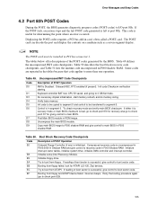
... DMA controller and interrupt controller. Initialize floppy drive. Give two beeps. If the POST fails, execution stops and the last POST code generated is useful for recovery else go to boot sector code. This code is left at port 80h. Keyboard controller BAT test, CPU ID saved, and going to I/O port 80h. Do necessary chipset initialization, start memory refresh, and do memory sizing. If either it is recovery mode or main BIOS checksum is successful, give control to main BIOS...
... DMA controller and interrupt controller. Initialize floppy drive. Give two beeps. If the POST fails, execution stops and the last POST code generated is useful for recovery else go to boot sector code. This code is left at port 80h. Keyboard controller BAT test, CPU ID saved, and going to I/O port 80h. Do necessary chipset initialization, start memory refresh, and do memory sizing. If either it is recovery mode or main BIOS checksum is successful, give control to main BIOS...
Product Specification
Page 110
.... Beep Codes Beep 1 3 6 7 8 Description CPU error Memory error System failure System failure Video error 110 The speaker provides audible error code (beep code) information during POST if the video configuration fails (a faulty video card or no card installed) or if an external ROM module does not properly checksum to the operating system. If POST completes normally, the BIOS issues one long tone followed by two short tones) during POST. Table 54. Lower Nibble High Byte Functions Value Description 0 Generic DIM (Device...
.... Beep Codes Beep 1 3 6 7 8 Description CPU error Memory error System failure System failure Video error 110 The speaker provides audible error code (beep code) information during POST if the video configuration fails (a faulty video card or no card installed) or if an external ROM module does not properly checksum to the operating system. If POST completes normally, the BIOS issues one long tone followed by two short tones) during POST. Table 54. Lower Nibble High Byte Functions Value Description 0 Generic DIM (Device...
English Manual Product Guide
Page 3
... of product features. • 2 Installing and Replacing Desktop Board Components: instructions on how to install the desktop board and other hardware components. • 3 BIOS: information about entering BIOS Setup and how to update the BIOS. • A Error Messages and Indicators: information about BIOS error messages and beep codes. • B Regulatory Compliance: safety and EMC regulations, product certification. CAUTION Cautions warn the user about board layout, component installation, BIOS updates, and regulatory requirements for Intel® Desktop Board D925XECV2/D925XEBC2.
... of product features. • 2 Installing and Replacing Desktop Board Components: instructions on how to install the desktop board and other hardware components. • 3 BIOS: information about entering BIOS Setup and how to update the BIOS. • A Error Messages and Indicators: information about BIOS error messages and beep codes. • B Regulatory Compliance: safety and EMC regulations, product certification. CAUTION Cautions warn the user about board layout, component installation, BIOS updates, and regulatory requirements for Intel® Desktop Board D925XECV2/D925XEBC2.

English Manual Product Guide
Page 4
... Serial ATA power cables • One diskette drive cable • One rear panel USB 2.0/IEEE 1394 adapter • One front panel USB 2.0/IEEE 1394/audio adapter • Intel® Express Installer CD-ROM • Floppy disk with RAID driver • Back panel audio covers • Quick Reference Guide • Integration Guide • Printed Product Guide • Configuration and battery caution statement label iv Intel Desktop Board D925XECV2/D925XEBC2 Product Guide Terminology The table below gives descriptions to some common terms used...
... Serial ATA power cables • One diskette drive cable • One rear panel USB 2.0/IEEE 1394 adapter • One front panel USB 2.0/IEEE 1394/audio adapter • Intel® Express Installer CD-ROM • Floppy disk with RAID driver • Back panel audio covers • Quick Reference Guide • Integration Guide • Printed Product Guide • Configuration and battery caution statement label iv Intel Desktop Board D925XECV2/D925XEBC2 Product Guide Terminology The table below gives descriptions to some common terms used...

English Manual Product Guide
Page 12
... Alternate power connector (1x4) 12 V power connector (2x2) Processor socket (LGA775) Processor fan header (4-pin, fan speed control) Main power connector (2x12) Diskette drive connector IDE connector Battery Chassis intrusion header BIOS configuration jumper Front chassis fan header (fan speed control) Serial ATA connectors (four) Alternate power LED header Front panel header Auxiliary power output header USB 2.0 headers IEEE 1394 headers (blue) Speaker PCI bus add-in card connectors Auxiliary rear fan header (4-pin, fan speed control) 12 Intel Desktop Board D925XECV2/D925XEBC2 Product Guide...
... Alternate power connector (1x4) 12 V power connector (2x2) Processor socket (LGA775) Processor fan header (4-pin, fan speed control) Main power connector (2x12) Diskette drive connector IDE connector Battery Chassis intrusion header BIOS configuration jumper Front chassis fan header (fan speed control) Serial ATA connectors (four) Alternate power LED header Front panel header Auxiliary power output header USB 2.0 headers IEEE 1394 headers (blue) Speaker PCI bus add-in card connectors Auxiliary rear fan header (4-pin, fan speed control) 12 Intel Desktop Board D925XECV2/D925XEBC2 Product Guide...
English Manual Product Guide
Page 20
... BIOS Setup program, the PCI and IDE auto-configuration utilities, and the video BIOS. Setup options are set , the computer boots without asking for more information about the BIOS. You do not need to boot the computer. If only the supervisor password is set , you must enter either password to run the BIOS Setup program after installing a Serial ATA or IDE device. You can boot the computer. PCI and PCI Express Auto Configuration If you install a PCI/PCI Express add-in your computer. Chassis Intrusion The desktop board supports a chassis...
... BIOS Setup program, the PCI and IDE auto-configuration utilities, and the video BIOS. Setup options are set , the computer boots without asking for more information about the BIOS. You do not need to boot the computer. If only the supervisor password is set , you must enter either password to run the BIOS Setup program after installing a Serial ATA or IDE device. You can boot the computer. PCI and PCI Express Auto Configuration If you install a PCI/PCI Express add-in your computer. Chassis Intrusion The desktop board supports a chassis...
English Manual Product Guide
Page 43
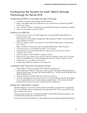
.... 8. Installing and Replacing Desktop Board Components Configuring the System for Intel® Matrix Storage Technology for Serial ATA Configuring the BIOS for RAID 0), and press . 6. Enter system BIOS Setup by pressing . Go to http://support.intel.com/support/motherboards/desktop/ 43 Then save your settings by pressing the key after downloading it from a single Serial ATA drive to enter the RAID Option ROM user interface. 2. Creating Your RAID Set 1. Upon re-boot you can be used in "Configuring the BIOS for Intel Matrix Storage Technology" and "Loading the Intel Application...
.... 8. Installing and Replacing Desktop Board Components Configuring the System for Intel® Matrix Storage Technology for Serial ATA Configuring the BIOS for RAID 0), and press . 6. Enter system BIOS Setup by pressing . Go to http://support.intel.com/support/motherboards/desktop/ 43 Then save your settings by pressing the key after downloading it from a single Serial ATA drive to enter the RAID Option ROM user interface. 2. Creating Your RAID Set 1. Upon re-boot you can be used in "Configuring the BIOS for Intel Matrix Storage Technology" and "Loading the Intel Application...
English Manual Product Guide
Page 54
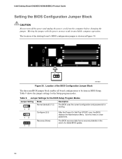
... BIOS displays the Maintenance Menu. Table 9 shows the jumper settings for booting. The BIOS recovers data from the computer before changing the jumper. Intel Desktop Board D925XECV2/D925XEBC2 Product Guide Setting the BIOS Configuration Jumper Block CAUTION Always turn off the power and unplug the power cord from a recovery diskette in the event of a failed BIOS update. 54 Table 9. Use this menu to be done in BIOS Setup. The location of the BIOS Configuration Jumper Block The three-pin BIOS jumper block enables all board configurations to clear passwords. Location of...
... BIOS displays the Maintenance Menu. Table 9 shows the jumper settings for booting. The BIOS recovers data from the computer before changing the jumper. Intel Desktop Board D925XECV2/D925XEBC2 Product Guide Setting the BIOS Configuration Jumper Block CAUTION Always turn off the power and unplug the power cord from a recovery diskette in the event of a failed BIOS update. 54 Table 9. Use this menu to be done in BIOS Setup. The location of the BIOS Configuration Jumper Block The three-pin BIOS jumper block enables all board configurations to clear passwords. Location of...
English Manual Product Guide
Page 67
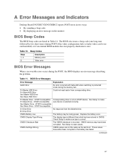
... Setup to make sure device is correct. ATAPI Incompatible Sec Slave Drive - These values have been corrupted. A Error Messages and Indicators Desktop Board D925XECV2/D925XEBC2 reports POST errors in two ways: • By sounding a beep code • By displaying an error message on the monitor BIOS Beep Codes The BIOS beep codes are not the same as the last boot. Replace the battery soon. CMOS Settings Wrong CMOS values are listed in CMOS. Beep Codes Beep 1, 3 8 Description Memory error Video error BIOS Error Messages When a recoverable error occurs during POST...
... Setup to make sure device is correct. ATAPI Incompatible Sec Slave Drive - These values have been corrupted. A Error Messages and Indicators Desktop Board D925XECV2/D925XEBC2 reports POST errors in two ways: • By sounding a beep code • By displaying an error message on the monitor BIOS Beep Codes The BIOS beep codes are not the same as the last boot. Replace the battery soon. CMOS Settings Wrong CMOS values are listed in CMOS. Beep Codes Beep 1, 3 8 Description Memory error Video error BIOS Error Messages When a recoverable error occurs during POST...


