
User Manual
Page 6
Intel Desktop Board D915GEV/D915GUX/D915GAV/D915GAG Product Guide Installing and Removing the Desktop Board 31 Installing and Removing a Processor 32 Installing a Processor 32 Installing the Processor Fan Heat Sink ... Re-tasking 47 Connecting Fan and Power Cables 48 Connecting Fan Cables 48 Connecting Power Cables 49 PCI Bus Add-In Card Connectors 51 Setting the BIOS Configuration Jumper Block 52 Clearing Passwords ...53 Back Panel Connectors...54 Replacing the Battery...55 3 BIOS Updating the BIOS with the Intel® Express BIOS Update Utility...
Intel Desktop Board D915GEV/D915GUX/D915GAV/D915GAG Product Guide Installing and Removing the Desktop Board 31 Installing and Removing a Processor 32 Installing a Processor 32 Installing the Processor Fan Heat Sink ... Re-tasking 47 Connecting Fan and Power Cables 48 Connecting Fan Cables 48 Connecting Power Cables 49 PCI Bus Add-In Card Connectors 51 Setting the BIOS Configuration Jumper Block 52 Clearing Passwords ...53 Back Panel Connectors...54 Replacing the Battery...55 3 BIOS Updating the BIOS with the Intel® Express BIOS Update Utility...
User Manual
Page 7
...and Peripheral Interface Connectors for Flexible 6-Channel Audio System 47 24. Connecting 2x10 Power Supply Cables 49 26. Back Panel Connectors 54 30. Installing a DIMM...39 19. Intel Desktop Boards D915GUX and D915GAG Components 14 3. Remove the Processor from the Protective Processor Cover/...Do Not Touch 33 11. Installing the I/O Shield 30 6. Desktop Boards D915GAV and D915GEV Components 12 2. Back Panel Audio Connectors for Desktop Boards...
...and Peripheral Interface Connectors for Flexible 6-Channel Audio System 47 24. Connecting 2x10 Power Supply Cables 49 26. Back Panel Connectors 54 30. Installing a DIMM...39 19. Intel Desktop Boards D915GUX and D915GAG Components 14 3. Remove the Processor from the Protective Processor Cover/...Do Not Touch 33 11. Installing the I/O Shield 30 6. Desktop Boards D915GAV and D915GEV Components 12 2. Back Panel Audio Connectors for Desktop Boards...
User Manual
Page 10
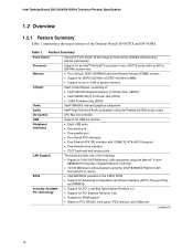
... for SMBIOS • Intel® Rapid BIOS Boot • Intel® Express BIOS Update Power Management • Support for Advanced Configuration and Power Interface (ACPI) • Suspend to RAM (STR) • Wake on USB, PCI, PCI Express, PS/2, LAN, and front panel Hardware Management Hardware monitor with...out of range values Security (Optional) Trusted Platform Module (Optional) Related Links: For more information about Intel Desktop Board D915GEV/D915GUX/D915GAV/D915GAG, including the Technical Product Specification (TPS), BIOS updates, and device drivers, go to: http://support...
... for SMBIOS • Intel® Rapid BIOS Boot • Intel® Express BIOS Update Power Management • Support for Advanced Configuration and Power Interface (ACPI) • Suspend to RAM (STR) • Wake on USB, PCI, PCI Express, PS/2, LAN, and front panel Hardware Management Hardware monitor with...out of range values Security (Optional) Trusted Platform Module (Optional) Related Links: For more information about Intel Desktop Board D915GEV/D915GUX/D915GAV/D915GAG, including the Technical Product Specification (TPS), BIOS updates, and device drivers, go to: http://support...
User Manual
Page 13
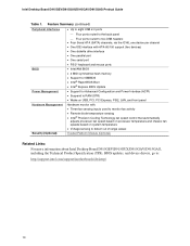
...S T U V W Desktop Boards D915GAV and D915GEV Components Description Front panel audio header PCI Express x16 connector Rear chassis fan header 1 (fan speed control) Alternate power connector (1x4) 12 V processor core voltage connector (2x2) Processor socket Processor fan header (4-pin, fan speed control) Main power connector (2x12) Diskette drive connector Primary IDE connector Battery... (optional) Front chassis fan header (fan speed control) Serial ATA connectors (four) Power LED header Front panel header USB 2.0 headers PCI bus add-in card connectors Speaker PCI Express x1 connectors Rear chassis...
...S T U V W Desktop Boards D915GAV and D915GEV Components Description Front panel audio header PCI Express x16 connector Rear chassis fan header 1 (fan speed control) Alternate power connector (1x4) 12 V processor core voltage connector (2x2) Processor socket Processor fan header (4-pin, fan speed control) Main power connector (2x12) Diskette drive connector Primary IDE connector Battery... (optional) Front chassis fan header (fan speed control) Serial ATA connectors (four) Power LED header Front panel header USB 2.0 headers PCI bus add-in card connectors Speaker PCI Express x1 connectors Rear chassis...
User Manual
Page 15
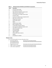
... Boards D915GAG and D915GUX Components Description Front panel audio header PCI Express x16 connector Rear chassis fan header (fan speed control) Alternate power connector (1x4) 12 V processor core voltage connector (2x2) Processor socket Processor fan header (4-pin, fan speed control) Main power connector (2x12) ...Intel Desktop Board D915GEV/D915GUX/ D915GAV/D915GAG • Supported processors http://www.intel.com/design/motherbd http://support.intel.com/support/motherboards/desktop http://support.intel.com/support/motherboards/desktop • Audio software and utilities http://www.intel...
... Boards D915GAG and D915GUX Components Description Front panel audio header PCI Express x16 connector Rear chassis fan header (fan speed control) Alternate power connector (1x4) 12 V processor core voltage connector (2x2) Processor socket Processor fan header (4-pin, fan speed control) Main power connector (2x12) ...Intel Desktop Board D915GEV/D915GUX/ D915GAV/D915GAG • Supported processors http://www.intel.com/design/motherbd http://support.intel.com/support/motherboards/desktop http://support.intel.com/support/motherboards/desktop • Audio software and utilities http://www.intel...
User Manual
Page 19
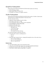
...D915GUX/D915GAV/D915GAG includes a flexible 6-channel audio subsystem based on a Realtek Semiconductor Corporation codec: The audio subsystem features: • Impedance sensing capability for jack re-tasking • S/N (signal-to-noise) ratio: > 90 dB • Power management support for ACPI 2.0 (driver dependent) • Intel...Supression (NX) technology The subsystem includes the following connectors: • Front panel audio connector, including pins for: ⎯ Line out ⎯ Line in • Back panel audio connectors that are configurable through the drivers of the audio devices: &#...
...D915GUX/D915GAV/D915GAG includes a flexible 6-channel audio subsystem based on a Realtek Semiconductor Corporation codec: The audio subsystem features: • Impedance sensing capability for jack re-tasking • S/N (signal-to-noise) ratio: > 90 dB • Power management support for ACPI 2.0 (driver dependent) • Intel...Supression (NX) technology The subsystem includes the following connectors: • Front panel audio connector, including pins for: ⎯ Line out ⎯ Line in • Back panel audio connectors that are configurable through the drivers of the audio devices: &#...
User Manual
Page 20
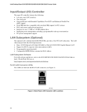
Back Panel LAN Connector LED Locations 20 Intel Desktop Board D915GEV/D915GUX/D915GAV/D915GAG Product Guide Input/Output (I/O) Controller The super I/O controller features the following functions: • Basic 10/100 Ethernet LAN (Intel 82562EZ) or Marvell 10/100/1000 Gigabit Ethernet LAN • Support for one 1.2 MB or 1.44 MB diskette drive • Intelligent power management...
Back Panel LAN Connector LED Locations 20 Intel Desktop Board D915GEV/D915GUX/D915GAV/D915GAG Product Guide Input/Output (I/O) Controller The super I/O controller features the following functions: • Basic 10/100 Ethernet LAN (Intel 82562EZ) or Marvell 10/100/1000 Gigabit Ethernet LAN • Support for one 1.2 MB or 1.44 MB diskette drive • Intelligent power management...

User Manual
Page 21
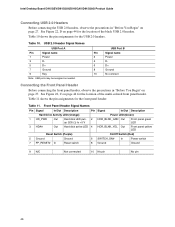
...LAN link is established. Disabling Hi-Speed USB in BIOS reverts all USB 2.0 ports to two internal USB 2.0 headers. four ports routed to the back panel and four routed to USB 1.1 operation. This may be required to the cable. LAN link is not established. USB 2.0 support requires both an operating... no device or a low-speed USB device is not established. Table 8. Desktop Board Features Table 7 describes the LED states when the board is powered up and the 10/100 Ethernet LAN subsystem is occurring. LAN activity is operating. Yellow Off On (steady state) 10 Mbits/sec data rate is...
...LAN link is established. Disabling Hi-Speed USB in BIOS reverts all USB 2.0 ports to two internal USB 2.0 headers. four ports routed to the back panel and four routed to USB 1.1 operation. This may be required to the cable. LAN link is not established. USB 2.0 support requires both an operating... no device or a low-speed USB device is not established. Table 8. Desktop Board Features Table 7 describes the LED states when the board is powered up and the 10/100 Ethernet LAN subsystem is occurring. LAN activity is operating. Yellow Off On (steady state) 10 Mbits/sec data rate is...
User Manual
Page 25
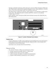
... following link, finding the product, and selecting Product Documentation from the left-hand menu: http://support.intel.com/support/motherboards/desktop/ Resume on Ring The operation of Resume on the front panel, the sleep state is standby power to -RAM) sleep state. Desktop Board Features Instantly Available PC technology enables the board to...
... following link, finding the product, and selecting Product Documentation from the left-hand menu: http://support.intel.com/support/motherboards/desktop/ Resume on Ring The operation of Resume on the front panel, the sleep state is standby power to -RAM) sleep state. Desktop Board Features Instantly Available PC technology enables the board to...
User Manual
Page 27
..., serial numbers, installed options, and configuration information. • Electrostatic discharge (ESD) can continue to operate even though the front panel power button is not available, you open the computer or perform any procedures can provide some ESD protection by wearing an antistatic wrist strap...personal computers and with jack re-tasking • Connect fans and power cables • Connect PCI bus add-in cards • Set the BIOS configuration jumper • Clear passwords • Locate back panel connectors • Replace the battery Before You Begin WARNINGS The procedures...
..., serial numbers, installed options, and configuration information. • Electrostatic discharge (ESD) can continue to operate even though the front panel power button is not available, you open the computer or perform any procedures can provide some ESD protection by wearing an antistatic wrist strap...personal computers and with jack re-tasking • Connect fans and power cables • Connect PCI bus add-in cards • Set the BIOS configuration jumper • Clear passwords • Locate back panel connectors • Replace the battery Before You Begin WARNINGS The procedures...
User Manual
Page 41
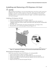
... card on the desktop board, ensure that secures the card's metal bracket to the chassis back panel with a screw (Figure 19, B). 4. Observe the precautions in the PCI Express x16 connector before you power on the card until the retention pin completely clears the notch in "Before You Begin" on... the over the back panel VGA port (Figure 19, C). Place the VGA cover over -current protection of the power supply, certain board components and/or traces may result across the PCI Express connector pins. If the ...
... card on the desktop board, ensure that secures the card's metal bracket to the chassis back panel with a screw (Figure 19, B). 4. Observe the precautions in the PCI Express x16 connector before you power on the card until the retention pin completely clears the notch in "Before You Begin" on... the over the back panel VGA port (Figure 19, C). Place the VGA cover over -current protection of the power supply, certain board components and/or traces may result across the PCI Express connector pins. If the ...
User Manual
Page 44
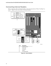
... 6 D+ 7 8 Ground 10 N/C D 9 No Connection On/Off 87 65 Reset Power LED 43 HD LED 3 21 1 C B Item A B C D E Description Chassis intrusion Power LED Front panel USB 2.0 Front panel audio Figure 22. Internal Headers 1 A OM16918 44 Figure 22 shows the location of the internal headers. Intel Desktop Board D915GEV/D915GUX/D915GAV/D915GAG Product Guide Connecting Internal Headers Before connecting...
... 6 D+ 7 8 Ground 10 N/C D 9 No Connection On/Off 87 65 Reset Power LED 43 HD LED 3 21 1 C B Item A B C D E Description Chassis intrusion Power LED Front panel USB 2.0 Front panel audio Figure 22. Internal Headers 1 A OM16918 44 Figure 22 shows the location of the internal headers. Intel Desktop Board D915GEV/D915GUX/D915GAV/D915GAG Product Guide Connecting Internal Headers Before connecting...
User Manual
Page 45
... all peripheral devices connected to the computer. Turn off the computer and disconnect the AC power cord. 3. Turn off the computer and disconnect the AC power cord. 3. Install a correctly keyed and shielded front panel audio cable. 6. Remove the front panel audio cable. 5. Install a jumper on pins 9-10 (rear L channel). 7. Install a jumper on pins 5-6 (rear...
... all peripheral devices connected to the computer. Turn off the computer and disconnect the AC power cord. 3. Turn off the computer and disconnect the AC power cord. 3. Install a correctly keyed and shielded front panel audio cable. 6. Remove the front panel audio cable. 5. Install a jumper on pins 9-10 (rear L channel). 7. Install a jumper on pins 5-6 (rear...
User Manual
Page 46
... pin assignments for the location of the black USB 2.0 headers. See Figure 22, C on page 44 for the USB 2.0 headers. Front Panel Header Signal Names Pin Signal In/Out Description Hard Drive Activity LED (Orange) 1 HD_PWR Out Hard disk LED pullup (330 Ω) to ... pin No pin 46 USB 2.0 Header Signal Names USB Port A Pin Signal name 1 Power 3 D- 5 D+ 7 Ground 9 Key Note: USB ports may be assigned as needed. Table 10. Intel Desktop Board D915GEV/D915GUX/D915GAV/D915GAG Product Guide Connecting USB 2.0 Headers Before connecting the USB 2.0 headers, observe the...
... pin assignments for the location of the black USB 2.0 headers. See Figure 22, C on page 44 for the USB 2.0 headers. Front Panel Header Signal Names Pin Signal In/Out Description Hard Drive Activity LED (Orange) 1 HD_PWR Out Hard disk LED pullup (330 Ω) to ... pin No pin 46 USB 2.0 Header Signal Names USB Port A Pin Signal name 1 Power 3 D- 5 D+ 7 Ground 9 Key Note: USB ports may be assigned as needed. Table 10. Intel Desktop Board D915GEV/D915GUX/D915GAV/D915GAG Product Guide Connecting USB 2.0 Headers Before connecting the USB 2.0 headers, observe the...
User Manual
Page 54
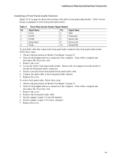
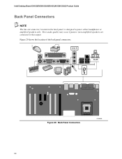
Figure 29 shows the location of the back panel connectors. Back Panel Connectors OM16900 54 Line In RJ45 Figure 29. Intel Desktop Board D915GEV/D915GUX/D915GAV/D915GAG Product Guide Back Panel Connectors NOTE The line out connector, located on the back panel, is designed to this output. Poor audio quality may occur if passive (non-amplified) speakers are connected to power either headphones or amplified speakers only.
Figure 29 shows the location of the back panel connectors. Back Panel Connectors OM16900 54 Line In RJ45 Figure 29. Intel Desktop Board D915GEV/D915GUX/D915GAV/D915GAG Product Guide Back Panel Connectors NOTE The line out connector, located on the back panel, is designed to this output. Poor audio quality may occur if passive (non-amplified) speakers are connected to power either headphones or amplified speakers only.
User Manual
Page 69
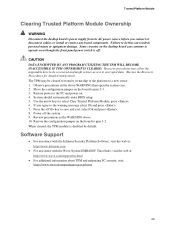
... jumper on . 4. If you connect or disconnect cables, or install or remove any board components. Power off . Use the arrow keys to save and exit, select Ok and press . 8. Software Support...precautions in the WARNING above WARNING then open the system case. 2. Restore power to the PC and power on the board to pins 2-3. 3. Restore the configuration jumper on the ... Trusted Platform Module Clearing Trusted Platform Module Ownership WARNING Disconnect the desktop board's power supply from its AC power source before you agree to the warning message select Ok and press . 7....
... jumper on . 4. If you connect or disconnect cables, or install or remove any board components. Power off . Use the arrow keys to save and exit, select Ok and press . 8. Software Support...precautions in the WARNING above WARNING then open the system case. 2. Restore power to the PC and power on the board to pins 2-3. 3. Restore the configuration jumper on the ... Trusted Platform Module Clearing Trusted Platform Module Ownership WARNING Disconnect the desktop board's power supply from its AC power source before you agree to the warning message select Ok and press . 7....
Product Specification
Page 6
Intel Desktop Board D915GUX/D915GHA Technical Product Specification 1.13.3 1.13.4...2.5 PCI Configuration Space Map 53 2.6 Interrupts ...54 2.7 PCI Conventional Interrupt Routing Map 55 2.8 Connectors...56 2.8.1 Back Panel Connectors 56 2.8.2 Component-side Connectors 58 2.9 Jumper Block ...67 2.10 Mechanical Considerations 68 2.10.1 Form Factor 68 2....DC Loading 70 2.11.2 Add-in Board Considerations 70 2.11.3 Fan Connector Current Capability 70 2.11.4 Power Supply Considerations 71 2.12 Thermal Considerations 72 2.13 Reliability ...74 2.14 Environmental ...74 2.15 Regulatory Compliance...
Intel Desktop Board D915GUX/D915GHA Technical Product Specification 1.13.3 1.13.4...2.5 PCI Configuration Space Map 53 2.6 Interrupts ...54 2.7 PCI Conventional Interrupt Routing Map 55 2.8 Connectors...56 2.8.1 Back Panel Connectors 56 2.8.2 Component-side Connectors 58 2.9 Jumper Block ...67 2.10 Mechanical Considerations 68 2.10.1 Form Factor 68 2....DC Loading 70 2.11.2 Add-in Board Considerations 70 2.11.3 Fan Connector Current Capability 70 2.11.4 Power Supply Considerations 71 2.12 Thermal Considerations 72 2.13 Reliability ...74 2.14 Environmental ...74 2.15 Regulatory Compliance...
Product Specification
Page 7
... 10. Processor Heatsink Airflow 72 25. Dual Channel (Interleaved) Mode Configuration with Three DIMMs 22 9. Location of the Standby Power Indicator LED 41 15. Localized High Temperature Zones 73 vii Contents 3.6 BIOS Updates ...82 3.6.1 Language Support 82 3.6.2 Custom Splash... Connector LED Locations 31 12. Connection Diagram for Front Panel Connector 64 19. Block Diagram ...16 3. Dual Channel (Interleaved) Mode Configuration with Intel® Rapid BIOS Boot 84 3.8.1 Peripheral Selection and Configuration 84 3.8.2 Intel Rapid BIOS Boot 84 3.9 BIOS Security Features 85 ...
... 10. Processor Heatsink Airflow 72 25. Dual Channel (Interleaved) Mode Configuration with Three DIMMs 22 9. Location of the Standby Power Indicator LED 41 15. Localized High Temperature Zones 73 vii Contents 3.6 BIOS Updates ...82 3.6.1 Language Support 82 3.6.2 Custom Splash... Connector LED Locations 31 12. Connection Diagram for Front Panel Connector 64 19. Block Diagram ...16 3. Dual Channel (Interleaved) Mode Configuration with Intel® Rapid BIOS Boot 84 3.8.1 Peripheral Selection and Configuration 84 3.8.2 Intel Rapid BIOS Boot 84 3.9 BIOS Security Features 85 ...
Product Specification
Page 8
... Connector (optional 61 24. DC Loading Characteristics 70 36. Power States and Targeted System Power 37 9. Serial ATA Connectors 61 27. Main Power Connector 62 28. Front Panel Connector 64 32. States for a Two-Color Power LED 65 34. BIOS Setup Program Menu Bar 80 43... Summary...12 2. Back Panel Connectors Shown in Figure 16 57 17. EMC Regulations ...75 41. System Memory Map 51 11. Effects of Pressing the Power Switch 36 8. Wake-up Devices and Events 38 10. Manufacturing Options 13 3. Intel Desktop Board D915GUX/D915GHA Technical Product Specification ...
... Connector (optional 61 24. DC Loading Characteristics 70 36. Power States and Targeted System Power 37 9. Serial ATA Connectors 61 27. Main Power Connector 62 28. Front Panel Connector 64 32. States for a Two-Color Power LED 65 34. BIOS Setup Program Menu Bar 80 43... Summary...12 2. Back Panel Connectors Shown in Figure 16 57 17. EMC Regulations ...75 41. System Memory Map 51 11. Effects of Pressing the Power Switch 36 8. Wake-up Devices and Events 38 10. Manufacturing Options 13 3. Intel Desktop Board D915GUX/D915GHA Technical Product Specification ...
Product Specification
Page 12
...provides one of the Desktop Boards D915GUX and D915GHA. Intel Desktop Board D915GUX/D915GHA Technical Product Specification 1.2 Overview ...Intel® 82562EZ Platform LAN Connect (PLC) device • Intel/AMI BIOS (resident in the 4 Mbit FWH) • Support for Advanced Configuration and Power...Intel® 82801FB I/O Controller Hub (ICH6) • 4 Mbit Firmware Hub (FWH) Intel® GMA900 onboard graphics subsystem Intel® High Definition Audio subsystem using the Realtek ALC860 audio codec LPC Bus I/O controller Support for up to RAM support • Wake on PCI, RS-232, front panel...
...provides one of the Desktop Boards D915GUX and D915GHA. Intel Desktop Board D915GUX/D915GHA Technical Product Specification 1.2 Overview ...Intel® 82562EZ Platform LAN Connect (PLC) device • Intel/AMI BIOS (resident in the 4 Mbit FWH) • Support for Advanced Configuration and Power...Intel® 82801FB I/O Controller Hub (ICH6) • 4 Mbit Firmware Hub (FWH) Intel® GMA900 onboard graphics subsystem Intel® High Definition Audio subsystem using the Realtek ALC860 audio codec LPC Bus I/O controller Support for up to RAM support • Wake on PCI, RS-232, front panel...


