
User Manual
Page 3
...A Error Messages and Indicators: information about how to prevent damage to important information. CAUTION Cautions warn the user about BIOS error messages and beep codes B Regulatory Compliance: safety and EMC regulations, product certification Conventions The following conventions are used in this manual: WARNING ... or loss of data. iii Preface This Product Guide gives information about board layout, component installation, BIOS update, and regulatory requirements for technically qualified personnel. It is intended for Intel® Desktop Board D915GEV/D915GUX/D915GAV/D915GAG.
...A Error Messages and Indicators: information about how to prevent damage to important information. CAUTION Cautions warn the user about BIOS error messages and beep codes B Regulatory Compliance: safety and EMC regulations, product certification Conventions The following conventions are used in this manual: WARNING ... or loss of data. iii Preface This Product Guide gives information about board layout, component installation, BIOS update, and regulatory requirements for technically qualified personnel. It is intended for Intel® Desktop Board D915GEV/D915GUX/D915GAV/D915GAG.
User Manual
Page 7
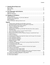
...Connecting the Processor Fan Heat Sink Cable to the Processor Fan Connector ........ 35 14. Internal Headers ...44 23. Location of the BIOS Configuration Jumper Block 52 29. Install Processor ...34 12. Dual Configuration Example 3 37 17. Back Panel Connectors 54 30. ...DMA Channels ...71 Interrupts ...72 A Error Messages and Indicators BIOS Beep Codes...73 BIOS Error Messages ...74 B Regulatory Compliance Safety Regulations ...77 European Union Declaration of Fan Headers 48 25. Intel Desktop Boards D915GUX and D915GAG Components 14 3. Remove the Processor from the Protective ...
...Connecting the Processor Fan Heat Sink Cable to the Processor Fan Connector ........ 35 14. Internal Headers ...44 23. Location of the BIOS Configuration Jumper Block 52 29. Install Processor ...34 12. Dual Configuration Example 3 37 17. Back Panel Connectors 54 30. ...DMA Channels ...71 Interrupts ...72 A Error Messages and Indicators BIOS Beep Codes...73 BIOS Error Messages ...74 B Regulatory Compliance Safety Regulations ...77 European Union Declaration of Fan Headers 48 25. Intel Desktop Boards D915GUX and D915GAG Components 14 3. Remove the Processor from the Protective ...
User Manual
Page 8
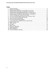
... ...71 15. Beep Codes...73 17. Product Certification Markings 80 viii Desktop Board D915GAV/D915GAG Memory Configurations 17 6. Jumper Settings for the BIOS Setup Program Modes 52 13. Safety Regulations ...77 19. Desktop Boards D915GAG and D915GUX Components 15 5. RJ-45...14. RJ-45 10/100/1000 Gigabit Ethernet LAN Connector LEDs 21 9. BIOS Error Messages...74 18. Feature Summary...9 2. Desktop Board D915GEV/D915GUX Memory Configurations 18 7. Intel Desktop Board D915GEV/D915GUX/D915GAV/D915GAG Product Guide Tables 1. Front Panel Audio Header Signal Names 45 10...
... ...71 15. Beep Codes...73 17. Product Certification Markings 80 viii Desktop Board D915GAV/D915GAG Memory Configurations 17 6. Jumper Settings for the BIOS Setup Program Modes 52 13. Safety Regulations ...77 19. Desktop Boards D915GAG and D915GUX Components 15 5. RJ-45...14. RJ-45 10/100/1000 Gigabit Ethernet LAN Connector LEDs 21 9. BIOS Error Messages...74 18. Feature Summary...9 2. Desktop Board D915GEV/D915GUX Memory Configurations 18 7. Intel Desktop Board D915GEV/D915GUX/D915GAV/D915GAG Product Guide Tables 1. Front Panel Audio Header Signal Names 45 10...
User Manual
Page 61
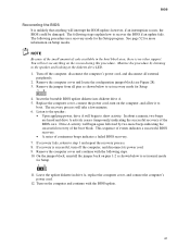
..., and allow it to set normal mode for Setup. 1 3 4. NOTE Because of the small amount of the boot block. BIOS Recovering the BIOS It is unlikely that anything on the screen during this procedure. The following procedure uses recovery mode for more beeps indicating the successful ...recovery of code available in drive A, replace the computer cover, and connect the computer's power cord. 12. Remove the computer cover and continue with the BIOS update. 61 however, if an interruption occurs, the...
..., and allow it to set normal mode for Setup. 1 3 4. NOTE Because of the small amount of the boot block. BIOS Recovering the BIOS It is unlikely that anything on the screen during this procedure. The following procedure uses recovery mode for more beeps indicating the successful ...recovery of code available in drive A, replace the computer cover, and connect the computer's power cord. 12. Remove the computer cover and continue with the BIOS update. 61 however, if an interruption occurs, the...
User Manual
Page 73
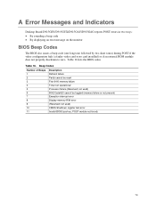
Table 16 lists the BIOS codes. Beep Codes Number of Beeps 1 2 3 4 5 6 7 8 9 10 11 Description Refresh failure Parity cannot be toggled (memory failure or not present) Exception interrupt error Display memory R/W error (Reserved; Table ..., POST module not found) 73 A Error Messages and Indicators Desktop Board D915GEV/D915GUX/D915GAV/D915GAG reports POST errors in two ways: • By sounding a beep code • By displaying an error message on the monitor BIOS Beep Codes The BIOS also issues a beep code (one long tone followed by two short tones) during POST if the...
Table 16 lists the BIOS codes. Beep Codes Number of Beeps 1 2 3 4 5 6 7 8 9 10 11 Description Refresh failure Parity cannot be toggled (memory failure or not present) Exception interrupt error Display memory R/W error (Reserved; Table ..., POST module not found) 73 A Error Messages and Indicators Desktop Board D915GEV/D915GUX/D915GAV/D915GAG reports POST errors in two ways: • By sounding a beep code • By displaying an error message on the monitor BIOS Beep Codes The BIOS also issues a beep code (one long tone followed by two short tones) during POST if the...
Product Specification
Page 3
... the Desktop Boards The features supported by the BIOS Setup program A description of the BIOS error messages, beep codes, and POST codes Typographical Conventions This section contains information about the Desktop Boards D915GUX and D915GHA and their components to system integrators....components, connectors, power and environmental requirements, and the BIOS for general audiences. INTEGRATOR'S NOTES Integrator's notes are included to important information. Not all specifications of these Intel® Desktop Boards: D915GUX and D915GHA. It is intended to provide detailed, ...
... the Desktop Boards The features supported by the BIOS Setup program A description of the BIOS error messages, beep codes, and POST codes Typographical Conventions This section contains information about the Desktop Boards D915GUX and D915GHA and their components to system integrators....components, connectors, power and environmental requirements, and the BIOS for general audiences. INTEGRATOR'S NOTES Integrator's notes are included to important information. Not all specifications of these Intel® Desktop Boards: D915GUX and D915GHA. It is intended to provide detailed, ...
Product Specification
Page 7
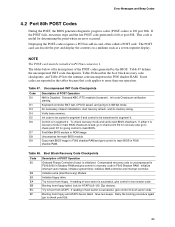
... 25. Dual Channel (Interleaved) Mode Configuration with Intel® Rapid BIOS Boot 84 3.8.1 Peripheral Selection and Configuration 84 3.8.2 Intel Rapid BIOS Boot 84 3.9 BIOS Security Features 85 4 Error Messages and Beep Codes 4.1 BIOS Error Messages 87 4.2 Port 80h POST Codes 89 4.3 Bus Initialization Checkpoints 93 4.4 Speaker...94 4.5 BIOS Beep Codes ...94 Figures 1. Contents 3.6 BIOS Updates ...82 3.6.1 Language Support 82 3.6.2 Custom Splash...
... 25. Dual Channel (Interleaved) Mode Configuration with Intel® Rapid BIOS Boot 84 3.8.1 Peripheral Selection and Configuration 84 3.8.2 Intel Rapid BIOS Boot 84 3.9 BIOS Security Features 85 4 Error Messages and Beep Codes 4.1 BIOS Error Messages 87 4.2 Port 80h POST Codes 89 4.3 Bus Initialization Checkpoints 93 4.4 Speaker...94 4.5 BIOS Beep Codes ...94 Figures 1. Contents 3.6 BIOS Updates ...82 3.6.1 Language Support 82 3.6.2 Custom Splash...

Product Specification
Page 79
.... 3 Overview of BIOS and a revision code. The BIOS displays a message during POST identifying the type of BIOS Features What This Chapter Contains 3.1 Introduction ...79 3.2 BIOS Flash Memory Organization 80 3.3 Resource Configuration 80 3.4 System Management BIOS (SMBIOS 81 3.5 Legacy USB Support 81 3.6 BIOS Updates ...82 3.7 Boot Options ...83 3.8 Fast Booting Systems with Intel® Rapid BIOS Boot 84 3.9 BIOS Security Features...
.... 3 Overview of BIOS and a revision code. The BIOS displays a message during POST identifying the type of BIOS Features What This Chapter Contains 3.1 Introduction ...79 3.2 BIOS Flash Memory Organization 80 3.3 Resource Configuration 80 3.4 System Management BIOS (SMBIOS 81 3.5 Legacy USB Support 81 3.6 BIOS Updates ...82 3.7 Boot Options ...83 3.8 Fast Booting Systems with Intel® Rapid BIOS Boot 84 3.9 BIOS Security Features...
Product Specification
Page 87
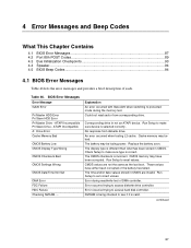
...stored in not an ATAPI device. Error occurred trying to protected mode during read sector from diskette drive. Table 46. BIOS Error Messages Error Message GA20 Error Pri Master HDD Error Pri Slave HDD Error Pri Master Drive - The CMOS checksum is... L2 cache. These values have been corrupted. 4 Error Messages and Beep Codes What This Chapter Contains 4.1 BIOS Error Messages 87 4.2 Port 80h POST Codes 89 4.3 Bus Initialization Checkpoints 93 4.4 Speaker...94 4.5 BIOS Beep Codes ...94 4.1 BIOS Error Messages Table 46 lists the error messages and provides a brief description ...
...stored in not an ATAPI device. Error occurred trying to protected mode during read sector from diskette drive. Table 46. BIOS Error Messages Error Message GA20 Error Pri Master HDD Error Pri Slave HDD Error Pri Master Drive - The CMOS checksum is... L2 cache. These values have been corrupted. 4 Error Messages and Beep Codes What This Chapter Contains 4.1 BIOS Error Messages 87 4.2 Port 80h POST Codes 89 4.3 Bus Initialization Checkpoints 93 4.4 Speaker...94 4.5 BIOS Beep Codes ...94 4.1 BIOS Error Messages Table 46 lists the error messages and provides a brief description ...
Product Specification
Page 89
.... If either it is recovery mode or main BIOS checksum is successful, give control to segment 0. Table 48. E8 Initialize extra (Intel Recovery) Module. EB Booting from floppy. Init code Checksum verification starting. D4 Verify base memory. NOTE The POST card must be transferred to recovery code in segment 0. Retry the booting procedure again...
.... If either it is recovery mode or main BIOS checksum is successful, give control to segment 0. Table 48. E8 Initialize extra (Intel Recovery) Module. EB Booting from floppy. Init code Checksum verification starting. D4 Verify base memory. NOTE The POST card must be transferred to recovery code in segment 0. Retry the booting procedure again...
Product Specification
Page 90
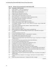
Intel Desktop Board D915GUX/D915GHA Technical Product Specification Table 49. Chipset init about to begin. 14 ...begin . To check soft reset/power-on . 12 To init CMOS if "Init CMOS in F000 Shadow RAM Code Description of different buses.) 3A New cursor position read 8042 input port and disable Megakey GreenPC feature. Going to disable...retrace checking. 34 Video display checking over. To do display memory R/W test. 2F EGA/VGA not found. Make BIOS code segment writeable. 24 To do any processing after video ROM returns control. 2E If EGA/VGA not found then do...
Intel Desktop Board D915GUX/D915GHA Technical Product Specification Table 49. Chipset init about to begin. 14 ...begin . To check soft reset/power-on . 12 To init CMOS if "Init CMOS in F000 Shadow RAM Code Description of different buses.) 3A New cursor position read 8042 input port and disable Megakey GreenPC feature. Going to disable...retrace checking. 34 Video display checking over. To do display memory R/W test. 2F EGA/VGA not found. Make BIOS code segment writeable. 24 To do any processing after video ROM returns control. 2E If EGA/VGA not found then do...
Product Specification
Page 92
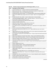
... Going to check extended keyboard, keyboard ID and num-lock. PS/2 Mouse check and extended BIOS data area allocation to optional ROM at E000. Optional ROM check and control will be done ...base address. A5 Going to get control next. Going to do any soft errors. Intel Desktop Board D915GUX/D915GHA Technical Product Specification Table 49. Hard disk setup to do any required processing after... To check for details of POST Operation 84 Lock-key checking over . To uncompress SETUP code and execute CMOS setup. 88 Returned from CMOS setup program and screen is done. Going to...
... Going to check extended keyboard, keyboard ID and num-lock. PS/2 Mouse check and extended BIOS data area allocation to optional ROM at E000. Optional ROM check and control will be done ...base address. A5 Going to get control next. Going to do any soft errors. Intel Desktop Board D915GUX/D915GHA Technical Product Specification Table 49. Hard disk setup to do any required processing after... To check for details of POST Operation 84 Lock-key checking over . To uncompress SETUP code and execute CMOS setup. 88 Returned from CMOS setup program and screen is done. Going to...
Product Specification
Page 93
...if present. The high byte of the checkpoint is the indication of the checkpoint is the system BIOS checkpoint from C800 to the different bus routines. B1 Going to copy any code to specific area. 00 Copying of different buses optional ROMs from which routine is passed to start...device init on the bus concerned. 6 func#6, error reporting for the bus concerned. 7 func#7, add-on the bus concerned. Error Messages and Beep Codes Table 49. Table 51. func#2, output device init on the bus concerned. Table 50. In these WORD checkpoints, the low byte of which the control...
...if present. The high byte of the checkpoint is the indication of the checkpoint is the system BIOS checkpoint from C800 to the different bus routines. B1 Going to copy any code to specific area. 00 Copying of different buses optional ROMs from which routine is passed to start...device init on the bus concerned. 6 func#6, error reporting for the bus concerned. 7 func#7, add-on the bus concerned. Error Messages and Beep Codes Table 49. Table 51. func#2, output device init on the bus concerned. Table 50. In these WORD checkpoints, the low byte of which the control...
Product Specification
Page 94
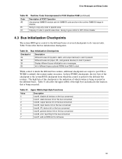
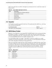
Intel Desktop Board D915GUX/D915GHA Technical Product Specification Table 52 describes the lower nibble of short tones. Lower Nibble High Byte Functions Value 0 1 2 Description Generic DIM (Device Initialization Manager) On-board System devices ISA devices 3 EISA devices 4 ISA PnP devices 5 PCI devices 4.4 Speaker A 47 inductive speaker is mounted on the beep codes... corner of the onboard speaker Refer to Figure 1, page 14 4.5 BIOS Beep Codes Whenever a recoverable error occurs during POST, the BIOS displays an error message describing the problem (see Table 53). There are...
Intel Desktop Board D915GUX/D915GHA Technical Product Specification Table 52 describes the lower nibble of short tones. Lower Nibble High Byte Functions Value 0 1 2 Description Generic DIM (Device Initialization Manager) On-board System devices ISA devices 3 EISA devices 4 ISA PnP devices 5 PCI devices 4.4 Speaker A 47 inductive speaker is mounted on the beep codes... corner of the onboard speaker Refer to Figure 1, page 14 4.5 BIOS Beep Codes Whenever a recoverable error occurs during POST, the BIOS displays an error message describing the problem (see Table 53). There are...


