User Manual
Page 5
... and PCI Express Auto Configuration 23 Security Passwords...23 Chassis Intrusion...23 Power Management Features 23 ACPI...23 Power Connectors...24 Fan Connectors...24 Fan Speed Control (Intel® Precision Cooling Technology 24 Suspend to RAM (Instantly Available PC Technology...-Time Clock...26 2 Installing and Replacing Desktop Board Components Before You Begin ...27 Installation Precautions ...28 Installation Instructions...28 Ensure Electromagnetic Compatibility (EMC) Compliance 28 Chassis and Component Certifications 29 Prevent Power Supply Overload 29 Place Battery Marking 29 Use ...
... and PCI Express Auto Configuration 23 Security Passwords...23 Chassis Intrusion...23 Power Management Features 23 ACPI...23 Power Connectors...24 Fan Connectors...24 Fan Speed Control (Intel® Precision Cooling Technology 24 Suspend to RAM (Instantly Available PC Technology...-Time Clock...26 2 Installing and Replacing Desktop Board Components Before You Begin ...27 Installation Precautions ...28 Installation Instructions...28 Ensure Electromagnetic Compatibility (EMC) Compliance 28 Chassis and Component Certifications 29 Prevent Power Supply Overload 29 Place Battery Marking 29 Use ...
User Manual
Page 7
...Beep Codes...73 BIOS Error Messages ...74 B Regulatory Compliance Safety Regulations ...77 European Union Declaration of Fan Headers 48 25. Desktop Boards D915GEV and D915GAV Mounting Screw Hole Locations 31 7. Connecting the Processor Fan Heat Sink Cable to the Processor Fan Connector ........ 35... the BIOS Configuration Jumper Block 52 29. Back Panel Connectors 54 30. Install Processor ...34 12. Connecting 2x12 Power Supply Cables 50 27. Intel Desktop Boards D915GUX and D915GAG Components 14 3. Dual Configuration Example 2 37 16. Removing the Battery ...58 vii Remove the...
...Beep Codes...73 BIOS Error Messages ...74 B Regulatory Compliance Safety Regulations ...77 European Union Declaration of Fan Headers 48 25. Desktop Boards D915GEV and D915GAV Mounting Screw Hole Locations 31 7. Connecting the Processor Fan Heat Sink Cable to the Processor Fan Connector ........ 35... the BIOS Configuration Jumper Block 52 29. Back Panel Connectors 54 30. Install Processor ...34 12. Connecting 2x12 Power Supply Cables 50 27. Intel Desktop Boards D915GUX and D915GAG Components 14 3. Dual Configuration Example 2 37 16. Removing the Battery ...58 vii Remove the...
User Manual
Page 16
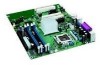
... Desktop Board D915GEV/D915GUX/D915GAV/D915GAG http://support.intel.com/support/motherboards/desktop/ • Instructions on installing or upgrading the processor, page 32 in Chapter 2 • The location of the two power connectors, page 48 in the LGA775 package. Desktop Boards D915GEV, D915GUX, D915GAV, and D915GAG support a single Intel Pentium 4 processor in Chapter 2 16 The processor connects to the desktop board and/or power supply. Intel Desktop Board D915GEV...
... Desktop Board D915GEV/D915GUX/D915GAV/D915GAG http://support.intel.com/support/motherboards/desktop/ • Instructions on installing or upgrading the processor, page 32 in Chapter 2 • The location of the two power connectors, page 48 in the LGA775 package. Desktop Boards D915GEV, D915GUX, D915GAV, and D915GAG support a single Intel Pentium 4 processor in Chapter 2 16 The processor connects to the desktop board and/or power supply. Intel Desktop Board D915GEV...
User Manual
Page 24
... Technology) Intel Precision Cooling Technology automatically adjusts the processor fan speed based on the processor thermal diode temperature and adjusts the chassis fan speeds depending on desktop boards D915GEV and D915GAV are controlled. The processor and chassis fan speed control features can damage the power supply and/or effect ACPI S3 sleep state functionality. Desktop boards D915GAG and...
... Technology) Intel Precision Cooling Technology automatically adjusts the processor fan speed based on the processor thermal diode temperature and adjusts the chassis fan speeds depending on desktop boards D915GEV and D915GAV are controlled. The processor and chassis fan speed control features can damage the power supply and/or effect ACPI S3 sleep state functionality. Desktop boards D915GAG and...

User Manual
Page 28
... computer. 28 If you do not follow these instructions or the instructions for the chassis are marked accordingly. Intel Desktop Board D915GEV/D915GUX/D915GAV/D915GAG Product Guide Installation Precautions When you increase safety risk and the possibility of noncompliance with regional laws...and module suppliers, you install and test the Intel desktop board, observe all warnings and cautions in the installation instructions. Read and adhere to qualified technical personnel. To avoid injury, be hazardous If the power supply and other modules or peripherals, as applicable, ...
... computer. 28 If you do not follow these instructions or the instructions for the chassis are marked accordingly. Intel Desktop Board D915GEV/D915GUX/D915GAV/D915GAG Product Guide Installation Precautions When you increase safety risk and the possibility of noncompliance with regional laws...and module suppliers, you install and test the Intel desktop board, observe all warnings and cautions in the installation instructions. Read and adhere to qualified technical personnel. To avoid injury, be hazardous If the power supply and other modules or peripherals, as applicable, ...
User Manual
Page 29
... Voltage directive (as CSA or cUL signifies compliance with an incorrect type. Installing and Replacing Desktop Board Components Chassis and Component Certifications Ensure that the calculated total current loads of all applicable European ...power supplies output circuits. There is required to provide instructions for the intended use signifies compliance with safety requirements. Additionally, other components are components certified for the country or market where used batteries must also be UL listed or recognized and suitable for replacing and disposing of this Desktop Board...
... Voltage directive (as CSA or cUL signifies compliance with an incorrect type. Installing and Replacing Desktop Board Components Chassis and Component Certifications Ensure that the calculated total current loads of all applicable European ...power supplies output circuits. There is required to provide instructions for the intended use signifies compliance with safety requirements. Additionally, other components are components certified for the country or market where used batteries must also be UL listed or recognized and suitable for replacing and disposing of this Desktop Board...
User Manual
Page 41
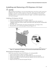
... 19. Depending on the over the back panel VGA port (Figure 19, C). Place the VGA cover over -current protection of the power supply, certain board components and/or traces may result across the PCI Express connector pins. Inserting the PCI Express x16 Card and Covering the Back Panel VGA...Card Follow these instructions to the chassis back panel. 3. Installing and Replacing Desktop Board Components Installing and Removing a PCI Express x16 Card CAUTION When installing any PCI Express x16 card on the desktop board, ensure that secures the card's metal bracket to remove the PCI Express...
... 19. Depending on the over the back panel VGA port (Figure 19, C). Place the VGA cover over -current protection of the power supply, certain board components and/or traces may result across the PCI Express connector pins. Inserting the PCI Express x16 Card and Covering the Back Panel VGA...Card Follow these instructions to the chassis back panel. 3. Installing and Replacing Desktop Board Components Installing and Removing a PCI Express x16 Card CAUTION When installing any PCI Express x16 card on the desktop board, ensure that secures the card's metal bracket to remove the PCI Express...

User Manual
Page 49
... voltage power supply cable to the 2x2 connector. 4. Installing and Replacing Desktop Board Components Connecting Power Cables CAUTION Failure to use an ATX12V power supply, or not connecting the 12 V (2x2) processor core voltage power supply connector to the desktop board may result in "Before You Begin" on the desktop board is recommended with ATX12V power supplies with 2x10 power connections. OM16854 49 Connecting 2x10 Power Supply Cables...
... voltage power supply cable to the 2x2 connector. 4. Installing and Replacing Desktop Board Components Connecting Power Cables CAUTION Failure to use an ATX12V power supply, or not connecting the 12 V (2x2) processor core voltage power supply connector to the desktop board may result in "Before You Begin" on the desktop board is recommended with ATX12V power supplies with 2x10 power connections. OM16854 49 Connecting 2x10 Power Supply Cables...

User Manual
Page 50
Observe the precautions in "Before You Begin" on page 27. 2. Intel Desktop Board D915GEV/D915GUX/D915GAV/D915GAG Product Guide Connecting 2x12 Power Supply Cables If you have a 2x12 power supply, follow the instruction below. Connecting 2x12 Power Supply Cables 1. OM16855 50 Connect the 12 V processor core voltage power supply cable to the 2x12 connector. Connect the main power supply cable to the 2x2 connector. 3. Figure 26 shows the location of the power connectors. 1 2 2X12 Figure 26.
Observe the precautions in "Before You Begin" on page 27. 2. Intel Desktop Board D915GEV/D915GUX/D915GAV/D915GAG Product Guide Connecting 2x12 Power Supply Cables If you have a 2x12 power supply, follow the instruction below. Connecting 2x12 Power Supply Cables 1. OM16855 50 Connect the 12 V processor core voltage power supply cable to the 2x12 connector. Connect the main power supply cable to the 2x2 connector. 3. Figure 26 shows the location of the power connectors. 1 2 2X12 Figure 26.
User Manual
Page 55
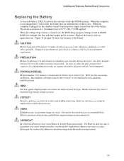
...;rdsbestämmelserna. Käytetyt paristot on page 58 shows the location of the battery. Installing and Replacing Desktop Board Components Replacing the Battery A coin-cell battery (CR2032) powers the real-time clock and CMOS memory. Les piles usagées doivent être recyclées dans... Herstellers entsprechend. 55 When the voltage drops below a certain level, the BIOS Setup program settings stored in , the standby current from the power supply extends the life of explosion if the battery is accurate to ± 13 minutes/year at 25 ºC with an incorrect type. CAUTION...
...;rdsbestämmelserna. Käytetyt paristot on page 58 shows the location of the battery. Installing and Replacing Desktop Board Components Replacing the Battery A coin-cell battery (CR2032) powers the real-time clock and CMOS memory. Les piles usagées doivent être recyclées dans... Herstellers entsprechend. 55 When the voltage drops below a certain level, the BIOS Setup program settings stored in , the standby current from the power supply extends the life of explosion if the battery is accurate to ± 13 minutes/year at 25 ºC with an incorrect type. CAUTION...
User Manual
Page 69
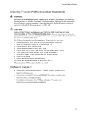
... to be cleared to transfer ownership of the platform to the PC and power on the board to pins 2-3. 3. Restore power to a new owner. 1. Restore the configuration jumper on . 4. Move the configuration jumper on the desktop board can result in personal injury or equipment damage. System should automatically enter BIOS...WILL BECOME INACCESSIBLE IF TPM OWNERSHIP IS CLEARED. Trusted Platform Module Clearing Trusted Platform Module Ownership WARNING Disconnect the desktop board's power supply from its AC power source before you agree to select Clear Trusted Platform Module, press . 6.
... to be cleared to transfer ownership of the platform to the PC and power on the board to pins 2-3. 3. Restore power to a new owner. 1. Restore the configuration jumper on . 4. Move the configuration jumper on the desktop board can result in personal injury or equipment damage. System should automatically enter BIOS...WILL BECOME INACCESSIBLE IF TPM OWNERSHIP IS CLEARED. Trusted Platform Module Clearing Trusted Platform Module Ownership WARNING Disconnect the desktop board's power supply from its AC power source before you agree to select Clear Trusted Platform Module, press . 6.


