User Manual
Page 4
Intel Desktop Board D915GEV/D915GUX/D915GAV/D915GAG Product Guide Terminology The table below gives descriptions to some common terms used in the product guide. Term Description GB Gigabyte (1,... (one billion hertz) KB Kilobyte (1024 bytes) MB Megabyte (1,048,576 bytes) Mbit Megabit (1,048,576 bits) MHz Megahertz (one million hertz) Box Contents • Intel Desktop Board • I/O shield • One IDE cable • Two SATA cables (second cable optional) • One diskette drive cable • One VGA port cover • Quick Reference...
Intel Desktop Board D915GEV/D915GUX/D915GAV/D915GAG Product Guide Terminology The table below gives descriptions to some common terms used in the product guide. Term Description GB Gigabyte (1,... (one billion hertz) KB Kilobyte (1024 bytes) MB Megabyte (1,048,576 bytes) Mbit Megabit (1,048,576 bits) MHz Megahertz (one million hertz) Box Contents • Intel Desktop Board • I/O shield • One IDE cable • Two SATA cables (second cable optional) • One diskette drive cable • One VGA port cover • Quick Reference...
User Manual
Page 5
... Manufacturing Options ...11 Supported Operating Systems 11 Desktop Board Components 12 Processor ...16 Main Memory ...17 Intel® 915G Express Chipset 18 Graphics Subsystem ...19 Audio Subsystem ...19 Input/Output (I/O) Controller 20 LAN ...and Replacing Desktop Board Components Before You Begin ...27 Installation Precautions ...28 Installation Instructions...28 Ensure Electromagnetic Compatibility (EMC) Compliance 28 Chassis and Component Certifications 29 Prevent Power Supply Overload 29 Place Battery Marking 29 Use Only for Intended Applications 30 Installing the I/O Shield ...30 ...
... Manufacturing Options ...11 Supported Operating Systems 11 Desktop Board Components 12 Processor ...16 Main Memory ...17 Intel® 915G Express Chipset 18 Graphics Subsystem ...19 Audio Subsystem ...19 Input/Output (I/O) Controller 20 LAN ...and Replacing Desktop Board Components Before You Begin ...27 Installation Precautions ...28 Installation Instructions...28 Ensure Electromagnetic Compatibility (EMC) Compliance 28 Chassis and Component Certifications 29 Prevent Power Supply Overload 29 Place Battery Marking 29 Use Only for Intended Applications 30 Installing the I/O Shield ...30 ...
User Manual
Page 7
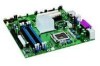
... Codes...73 BIOS Error Messages ...74 B Regulatory Compliance Safety Regulations ...77 European Union Declaration of Fan Headers 48 25. Desktop Boards D915GEV and D915GAV Mounting Screw Hole Locations 31 7. Remove the Protective Socket Cover 33 10. Remove the Processor from the ...Serial ATA Cable 43 22. Desktop Boards D915GAV and D915GEV Components 12 2. Installing the I/O Shield 30 6. Close the Load Plate ...34 13. Matching the Correct DIMM 38 18. Internal Headers ...44 23. Connecting 2x10 Power Supply Cables 49 26. Intel Desktop Boards D915GUX and D915GAG Components 14 ...
... Codes...73 BIOS Error Messages ...74 B Regulatory Compliance Safety Regulations ...77 European Union Declaration of Fan Headers 48 25. Desktop Boards D915GEV and D915GAV Mounting Screw Hole Locations 31 7. Remove the Protective Socket Cover 33 10. Remove the Processor from the ...Serial ATA Cable 43 22. Desktop Boards D915GAV and D915GEV Components 12 2. Installing the I/O Shield 30 6. Close the Load Plate ...34 13. Matching the Correct DIMM 38 18. Internal Headers ...44 23. Connecting 2x10 Power Supply Cables 49 26. Intel Desktop Boards D915GUX and D915GAG Components 14 ...

User Manual
Page 21
...port might not meet FCC Class B requirements, even if no device or a low-speed USB device is communicating with USB 1.1 devices. Use a shielded cable that fully support USB 2.0 transfer rates. This may be required to the cable. LAN link is occurring. USB 1.1 devices will function normally... Mbit/sec data rate is selected. 1 Gbit/sec data rate is not established. LAN link is operating. Desktop Board Features Table 7 describes the LED states when the board is powered up and the 10/100 Ethernet LAN subsystem is not established. Table 8 describes the LED states when...
...port might not meet FCC Class B requirements, even if no device or a low-speed USB device is communicating with USB 1.1 devices. Use a shielded cable that fully support USB 2.0 transfer rates. This may be required to the cable. LAN link is occurring. USB 1.1 devices will function normally... Mbit/sec data rate is selected. 1 Gbit/sec data rate is not established. LAN link is operating. Desktop Board Features Table 7 describes the LED states when the board is powered up and the 10/100 Ethernet LAN subsystem is not established. Table 8 describes the LED states when...
User Manual
Page 27
...with the safety practices and regulatory compliance required for using an antistatic wrist strap and a conductive foam pad. 2 Installing and Replacing Desktop Board Components This chapter tells you can provide some ESD protection by wearing an antistatic wrist strap and attaching it to a metal part ... continue to operate even though the front panel power button is not available, you how to: • Install the I/O shield • Install and remove the desktop board • Install and remove a processor and memory • Install and remove a PCI Express x16 card • Connect the IDE ...
...with the safety practices and regulatory compliance required for using an antistatic wrist strap and a conductive foam pad. 2 Installing and Replacing Desktop Board Components This chapter tells you can provide some ESD protection by wearing an antistatic wrist strap and attaching it to a metal part ... continue to operate even though the front panel power button is not available, you how to: • Install the I/O shield • Install and remove the desktop board • Install and remove a processor and memory • Install and remove a PCI Express x16 card • Connect the IDE ...

User Manual
Page 28
...Read and adhere to meet safety and regulatory requirements when installing this board. Intel Desktop Board D915GEV/D915GUX/D915GAV/D915GAG Product Guide Installation Precautions When you install and test the Intel desktop board, observe all warnings and cautions that instruct you to refer computer... on printed circuit assemblies • Rough edges and sharp corners on a representative sample of certifications • External I/O cable shielding and filtering • Mounting, grounding, and bonding requirements • Keying connectors when mating the wrong connectors could cause a short...
...Read and adhere to meet safety and regulatory requirements when installing this board. Intel Desktop Board D915GEV/D915GUX/D915GAV/D915GAG Product Guide Installation Precautions When you install and test the Intel desktop board, observe all warnings and cautions that instruct you to refer computer... on printed circuit assemblies • Rough edges and sharp corners on a representative sample of certifications • External I/O cable shielding and filtering • Mounting, grounding, and bonding requirements • Keying connectors when mating the wrong connectors could cause a short...

User Manual
Page 30
... the chassis as medical, industrial, alarm systems, test equipment, etc. Figure 5. Installing the I /O shield. Press the shield into place so that it fits tightly and securely. Intel Desktop Board D915GEV/D915GUX/D915GAV/D915GAG Product Guide Use Only for Intended Applications All Intel desktop boards are evaluated as Information Technology Equipment (I.T.E.) for use in personal computers for other applications...
... the chassis as medical, industrial, alarm systems, test equipment, etc. Figure 5. Installing the I /O shield. Press the shield into place so that it fits tightly and securely. Intel Desktop Board D915GEV/D915GUX/D915GAV/D915GAG Product Guide Use Only for Intended Applications All Intel desktop boards are evaluated as Information Technology Equipment (I.T.E.) for use in personal computers for other applications...
User Manual
Page 45
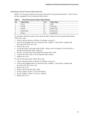
... front panel audio header, follow these steps: 1. Remove the cover. 4. Install a correctly keyed and shielded front panel audio cable. 6. Turn off all peripheral devices connected to the computer. Remove the front panel audio cable. 5. Installing and Replacing Desktop Board Components Installing a Front Panel Audio Solution Figure 22, E on pins 9-10 (rear L channel). 7. Turn...
... front panel audio header, follow these steps: 1. Remove the cover. 4. Install a correctly keyed and shielded front panel audio cable. 6. Turn off all peripheral devices connected to the computer. Remove the front panel audio cable. 5. Installing and Replacing Desktop Board Components Installing a Front Panel Audio Solution Figure 22, E on pins 9-10 (rear L channel). 7. Turn...
User Manual
Page 63
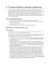
System Requirements • Intel Desktop Board D915GEV or D915GUX with the TPM will be recovered and...keys. The TPM is available. The owner/user should backup the system hard disk on Intel Express Installer CD) Warning of the motherboard, recovery procedures may allow migratable keys to be recovered and may be cleared (via a...keys at their associated data will render encrypted data inaccessible. No password recovery is specifically designed to shield unencrypted keys and platform authentication information from backup before access to encrypted data may become inaccessible or ...
System Requirements • Intel Desktop Board D915GEV or D915GUX with the TPM will be recovered and...keys. The TPM is available. The owner/user should backup the system hard disk on Intel Express Installer CD) Warning of the motherboard, recovery procedures may allow migratable keys to be recovered and may be cleared (via a...keys at their associated data will render encrypted data inaccessible. No password recovery is specifically designed to shield unencrypted keys and platform authentication information from backup before access to encrypted data may become inaccessible or ...