Product Guide
Page 5
Contents 1 Desktop Board Features Supported Operating Systems 13 Desktop Board Components 14 Processor ...16 Main Memory ...17 Intel® 875P Chipset ...18 Input/Output (I/O) Controller 18 LAN Subsystem...18 LAN Subsystem Software 18 RJ-45 LAN Connector LEDs 19 Hi-Speed USB 2.0......23 Fan Connectors ...23 Fan Speed Control (Intel® Precision Cooling Technology 23 Chassis Intrusion ...24 Resume on Ring...24 Wake from USB...24 Wake from PS/2 Keyboard/Mouse 24 PME# Wakeup Support 24 Speaker...25 Battery...25 Real-Time Clock...25 2 Installing and Replacing Desktop Board Components ...
Contents 1 Desktop Board Features Supported Operating Systems 13 Desktop Board Components 14 Processor ...16 Main Memory ...17 Intel® 875P Chipset ...18 Input/Output (I/O) Controller 18 LAN Subsystem...18 LAN Subsystem Software 18 RJ-45 LAN Connector LEDs 19 Hi-Speed USB 2.0......23 Fan Connectors ...23 Fan Speed Control (Intel® Precision Cooling Technology 23 Chassis Intrusion ...24 Resume on Ring...24 Wake from USB...24 Wake from PS/2 Keyboard/Mouse 24 PME# Wakeup Support 24 Speaker...25 Battery...25 Real-Time Clock...25 2 Installing and Replacing Desktop Board Components ...
Product Guide
Page 6
Intel Desktop Board D875PBZ Product Guide Installing the I/O Shield...30 Installing and Removing the Desktop Board 31 Installing and Removing a Processor 32 Installing a Processor 32 Installing the Processor Fan Heat Sink 32 Connecting the Processor Fan Heat Sink Cable 33 Removing the Processor 33 Installing and ...Connecting Hardware Control and Power Cables 46 Connecting Hardware Control Cables 47 Connecting Power Cables 47 Setting the BIOS Configuration Jumper Block 48 Clearing Passwords ...49 Replacing the Battery ...50 3 Updating the BIOS Updating the BIOS with the Intel® ...
Intel Desktop Board D875PBZ Product Guide Installing the I/O Shield...30 Installing and Removing the Desktop Board 31 Installing and Removing a Processor 32 Installing a Processor 32 Installing the Processor Fan Heat Sink 32 Connecting the Processor Fan Heat Sink Cable 33 Removing the Processor 33 Installing and ...Connecting Hardware Control and Power Cables 46 Connecting Hardware Control Cables 47 Connecting Power Cables 47 Setting the BIOS Configuration Jumper Block 48 Clearing Passwords ...49 Replacing the Battery ...50 3 Updating the BIOS Updating the BIOS with the Intel® ...

Product Guide
Page 7
Contents Video Configuration Submenu 70 USB Configuration Submenu 71 Chipset Configuration Submenu 72 Fan Control Submenu 74 Hardware Monitoring Submenu 75 Security Menu ...76 Power Menu ...77 APM Submenu ...78 ACPI Submenu...80 Boot Menu...81 Boot Device ... Devices Submenu 84 ATAPI CD-ROM Drives 85 Exit Menu ...86 5 Technical Reference Back Panel Connectors ...88 Add-In Card and Peripheral Interface Connectors 89 Desktop Board Resources 90 Memory Map ...90 DMA Channels ...90 Interrupts ...91 A Error Messages and Indicators BIOS Beep Codes ...93 BIOS Error Messages...94 B Regulatory ...
Contents Video Configuration Submenu 70 USB Configuration Submenu 71 Chipset Configuration Submenu 72 Fan Control Submenu 74 Hardware Monitoring Submenu 75 Security Menu ...76 Power Menu ...77 APM Submenu ...78 ACPI Submenu...80 Boot Menu...81 Boot Device ... Devices Submenu 84 ATAPI CD-ROM Drives 85 Exit Menu ...86 5 Technical Reference Back Panel Connectors ...88 Add-In Card and Peripheral Interface Connectors 89 Desktop Board Resources 90 Memory Map ...90 DMA Channels ...90 Interrupts ...91 A Error Messages and Indicators BIOS Beep Codes ...93 BIOS Error Messages...94 B Regulatory ...

Product Guide
Page 8
... 63 15. Video Configuration Submenu 70 20. Chipset Configuration Submenu 72 22. Security Menu ...76 25. Intel Desktop Board D875PBZ Product Guide Figures 1. Location of the BIOS Configuration Jumper Block 48 16. Installing DIMMs...34 8. Back ... 44 5. Boot Configuration Submenu 62 14. Power Menu...77 26. Desktop Board Components 14 2. Connecting the Processor Fan Heat Sink Cable to the Processor Fan Connector 33 7. Dual Configuration Example with Two DIMMs 35 9. Replacing... Submenu 65 16. Location of Hardware Control Headers and Power Connectors 46 15.
... 63 15. Video Configuration Submenu 70 20. Chipset Configuration Submenu 72 22. Security Menu ...76 25. Intel Desktop Board D875PBZ Product Guide Figures 1. Location of the BIOS Configuration Jumper Block 48 16. Installing DIMMs...34 8. Back ... 44 5. Boot Configuration Submenu 62 14. Power Menu...77 26. Desktop Board Components 14 2. Connecting the Processor Fan Heat Sink Cable to the Processor Fan Connector 33 7. Dual Configuration Example with Two DIMMs 35 9. Replacing... Submenu 65 16. Location of Hardware Control Headers and Power Connectors 46 15.
Product Guide
Page 12
... temperature sensing • Intel® Precision Cooling Technology fan speed control that automatically adjusts chassis fan speeds based on system temperature • Voltage sensing to detect out of range values Related Links: For more information about Intel Desktop Board D875PBZ, including the Technical Product Specification (TPS), BIOS updates, and device drivers, go to: http://support.intel.com/support/motherboards/desktop/ 12
... temperature sensing • Intel® Precision Cooling Technology fan speed control that automatically adjusts chassis fan speeds based on system temperature • Voltage sensing to detect out of range values Related Links: For more information about Intel Desktop Board D875PBZ, including the Technical Product Specification (TPS), BIOS updates, and device drivers, go to: http://support.intel.com/support/motherboards/desktop/ 12

Product Guide
Page 15
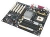
... fan header (fan speed control) O Serial ATA headers P BIOS configuration jumper Q USB 2.0 header R Front panel header S Speaker T Power LED header U Chassis intrusion header V Battery W Intel 82801ER (ICH5R) X PCI bus add-in card connectors Related Links: Go to the following links for more information about: • Intel Desktop Board D875PBZ http://www.intel.com/design/motherbd http://support.intel.com/support/motherboards/desktop...
... fan header (fan speed control) O Serial ATA headers P BIOS configuration jumper Q USB 2.0 header R Front panel header S Speaker T Power LED header U Chassis intrusion header V Battery W Intel 82801ER (ICH5R) X PCI bus add-in card connectors Related Links: Go to the following links for more information about: • Intel Desktop Board D875PBZ http://www.intel.com/design/motherbd http://support.intel.com/support/motherboards/desktop...

Product Guide
Page 22
... the computer will appear to RAM (Instantly Available PC technology) Power connectors Fan connectors Chassis intrusion Resume on Ring Wake from USB ... PS/2 keyboard/mouse PME# wakeup support ACPI ACPI gives the operating system direct control over the power management and Plug & Play functions of a computer. APM APM makes it...power to its last known awake state. 22 While in the BIOS Setup program. Intel Desktop Board D875PBZ Product Guide Power Management Features Power management is implemented at several levels, including: &#...
... the computer will appear to RAM (Instantly Available PC technology) Power connectors Fan connectors Chassis intrusion Resume on Ring Wake from USB ... PS/2 keyboard/mouse PME# wakeup support ACPI ACPI gives the operating system direct control over the power management and Plug & Play functions of a computer. APM APM makes it...power to its last known awake state. 22 While in the BIOS Setup program. Intel Desktop Board D875PBZ Product Guide Power Management Features Power management is implemented at several levels, including: &#...

Product Guide
Page 23
... the Standby Power Indicator CAUTION Power supplies used with this desktop board must be off. If the standby current necessary to the system. Fan Speed Control (Intel® Precision Cooling Technology) Intel Precision Cooling Technology automatically adjusts the chassis fan speeds depending on standby current requirements for these desktop boards, refer to page 46 for the location of the...
... the Standby Power Indicator CAUTION Power supplies used with this desktop board must be off. If the standby current necessary to the system. Fan Speed Control (Intel® Precision Cooling Technology) Intel Precision Cooling Technology automatically adjusts the chassis fan speeds depending on standby current requirements for these desktop boards, refer to page 46 for the location of the...
Product Guide
Page 24
... a mechanical switch on the chassis that can be disabled if a self-controlled fan is attached to the front and rear chassis fan connectors. Wake from PS/2 Keyboard/Mouse PS/2 keyboard/mouse activity wakes the computer from USB. Intel Desktop Board D875PBZ Product Guide fans connected to a chassis fan connector. Related Links: Go to access the computer • Detects incoming...
... a mechanical switch on the chassis that can be disabled if a self-controlled fan is attached to the front and rear chassis fan connectors. Wake from PS/2 Keyboard/Mouse PS/2 keyboard/mouse activity wakes the computer from USB. Intel Desktop Board D875PBZ Product Guide fans connected to a chassis fan connector. Related Links: Go to access the computer • Detects incoming...

Product Guide
Page 46
Chassis rear fan 1 J5B1 12 V Processor core voltage connector 1 2 VREG fan 1 J6B1 Processor fan 1 J1F1 Chassis intrusion 1 J8H1 Chassis front fan 1 J7J1 Main power connector 2 1 OM15679 Figure 14. Intel Desktop Board D875PBZ Product Guide Connecting Hardware Control and Power Cables Figure 14 shows the location of Hardware Control Headers and Power Connectors 46 Location of the hardware control (fans and chassis intrusion) headers and power supply connectors.
Chassis rear fan 1 J5B1 12 V Processor core voltage connector 1 2 VREG fan 1 J6B1 Processor fan 1 J1F1 Chassis intrusion 1 J8H1 Chassis front fan 1 J7J1 Main power connector 2 1 OM15679 Figure 14. Intel Desktop Board D875PBZ Product Guide Connecting Hardware Control and Power Cables Figure 14 shows the location of Hardware Control Headers and Power Connectors 46 Location of the hardware control (fans and chassis intrusion) headers and power supply connectors.
Product Guide
Page 47
... connecting the 12 V processor core voltage power supply connector to the desktop board may result in damage to its respective header on the board. Connect the main power supply cable to the board fan headers. See Figure 14 for header locations. Figure 14 shows the ... precautions in "Before You Begin" on page 27. Connect chassis fan cables to the 2x10 connector. 47 Connect the processor's fan heat sink cable to the 2x2 connector. 3. Installing and Replacing Desktop Board Components Connecting Hardware Control Cables Observe the precautions in "Before You Begin" on page 27...
... connecting the 12 V processor core voltage power supply connector to the desktop board may result in damage to its respective header on the board. Connect the main power supply cable to the board fan headers. See Figure 14 for header locations. Figure 14 shows the ... precautions in "Before You Begin" on page 27. Connect chassis fan cables to the 2x10 connector. 47 Connect the processor's fan heat sink cable to the 2x2 connector. 3. Installing and Replacing Desktop Board Components Connecting Hardware Control Cables Observe the precautions in "Before You Begin" on page 27...

Product Guide
Page 60
... ` Video Configuration ` USB Configuration ` Chipset Configuration ` Fan Control Configuration ` Hardware Management m o n p Enter F1 ...fan control features. When selected, displays the Fan Control Configuration submenu. When selected, displays the Peripheral Configuration submenu. Configures chipset features. Configures Plug & Play and the Numlock key, and resets configuration data. When selected, displays the USB Configuration submenu. When selected, displays the Chipset Configuration submenu. Configures the floppy drive(s). Configures video features. Intel Desktop Board D875PBZ...
... ` Video Configuration ` USB Configuration ` Chipset Configuration ` Fan Control Configuration ` Hardware Management m o n p Enter F1 ...fan control features. When selected, displays the Fan Control Configuration submenu. When selected, displays the Peripheral Configuration submenu. Configures chipset features. Configures Plug & Play and the Numlock key, and resets configuration data. When selected, displays the USB Configuration submenu. When selected, displays the Chipset Configuration submenu. Configures the floppy drive(s). Configures video features. Intel Desktop Board D875PBZ...

Product Guide
Page 74
... continue to configure hardware management features. After saving the BIOS settings and turning the system off the fans at the lowest system temperature. Intel Desktop Board D875PBZ Product Guide Fan Control Submenu Main Advanced Security Power Boot Exit Fan Control Configuration Setup Warning: These options will not take effect until power has been completely removed from the system and...
... continue to configure hardware management features. After saving the BIOS settings and turning the system off the fans at the lowest system temperature. Intel Desktop Board D875PBZ Product Guide Fan Control Submenu Main Advanced Security Power Boot Exit Fan Control Configuration Setup Warning: These options will not take effect until power has been completely removed from the system and...


