
D865PCK Technical Product Specification
Page 7
...10. I /O Map ...32 12. Characteristics of Single Channel Configuration with Dynamic Mode 17 6. Power States and Targeted System Power 26 8. Main Power Connector 43 21. Example of Dual/Single Channel Configuration with Dynamic Mode 17 5. Localized High Temperature Zones 56 Tables 1. I /O Shield... 15 4. Interrupts ...34 14. PCI Interrupt Routing Map 36 15. Example of Pressing the Power Switch 25 7. Desktop Board D865PCK Dimensions 52 17. Power and Hardware Control Connectors 42 11. Rear Chassis Fan Connector 43 18. Processor Fan Connector 43 20....
...10. I /O Map ...32 12. Characteristics of Single Channel Configuration with Dynamic Mode 17 6. Power States and Targeted System Power 26 8. Main Power Connector 43 21. Example of Dual/Single Channel Configuration with Dynamic Mode 17 5. Localized High Temperature Zones 56 Tables 1. I /O Shield... 15 4. Interrupts ...34 14. PCI Interrupt Routing Map 36 15. Example of Pressing the Power Switch 25 7. Desktop Board D865PCK Dimensions 52 17. Power and Hardware Control Connectors 42 11. Rear Chassis Fan Connector 43 18. Processor Fan Connector 43 20....
D865PCK Technical Product Specification
Page 37
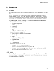
..., the power cable, and the external devices themselves. This section describes the board's connectors. The other internal connectors are installed at least 1.5 inches above the main power connector, the diskette drive connector, the Parallel ATA IDE connectors, and the DIMM sockets. 37 A fault in a microATX chassis, make sure that peripheral devices...
..., the power cable, and the external devices themselves. This section describes the board's connectors. The other internal connectors are installed at least 1.5 inches above the main power connector, the diskette drive connector, the Parallel ATA IDE connectors, and the DIMM sockets. 37 A fault in a microATX chassis, make sure that peripheral devices...
D865PCK Technical Product Specification
Page 39
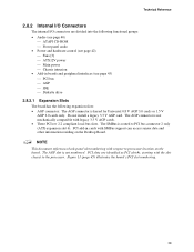
... slot #x, starting with the slot closest to the processor. PCI add-in boards and peripheral interfaces (see page 42) ⎯ Fans [3] ⎯ ATX12V power ⎯ Main power ⎯ Chassis intrusion • Add-in cards with SMBus support can access sensor data and other information residing on the board. PCI slots are...
... slot #x, starting with the slot closest to the processor. PCI add-in boards and peripheral interfaces (see page 42) ⎯ Fans [3] ⎯ ATX12V power ⎯ Main power ⎯ Chassis intrusion • Add-in cards with SMBus support can access sensor data and other information residing on the board. PCI slots are...
D865PCK Technical Product Specification
Page 42
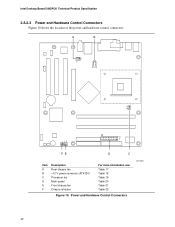
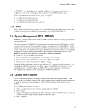
Power and Hardware Control Connectors OM17036 42 Intel Desktop Board D865PCK Technical Product Specification 2.8.2.3 Power and Hardware Control Connectors Figure 10 shows the location of the power and hardware control connectors. A B 1 3 12 34 1 3 113 20 11 1 FE D C Item A B C D E F Description Rear chassis fan +12 V power connector (ATX12V) Processor fan Main power Front chassis fan Chassis intrusion For more information see: Table 17 Table 18 Table 19 Table 20 Table 21 Table 22 Figure 10.
Power and Hardware Control Connectors OM17036 42 Intel Desktop Board D865PCK Technical Product Specification 2.8.2.3 Power and Hardware Control Connectors Figure 10 shows the location of the power and hardware control connectors. A B 1 3 12 34 1 3 113 20 11 1 FE D C Item A B C D E F Description Rear chassis fan +12 V power connector (ATX12V) Processor fan Main power Front chassis fan Chassis intrusion For more information see: Table 17 Table 18 Table 19 Table 20 Table 21 Table 22 Figure 10.
D865PCK Technical Product Specification
Page 43
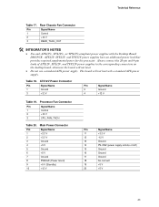
... on /off) 15 Ground 16 Ground 17 Ground 18 No connect 19 +5 V 20 +5 V 43 Processor Fan Connector Pin Signal Name 1 Control 2 +12 V 3 CPU_FAN_TACH Table 20. Main Power Connector Pin Signal Name 1 +3.3 V 2 +3.3 V 3 Ground 4 +5 V 5 Ground 6 +5 V 7 Ground 8 PWRGD (Power Good) 9 +5 V (Standby) 10 +12... PS-ON# (power supply remote on the desktop board, otherwise the board will not boot with the Desktop Board D865PCK. ATX12V, SFX12V, and TFX12V power supplies have an additional power lead that provides required supplemental power for the processor....
... on /off) 15 Ground 16 Ground 17 Ground 18 No connect 19 +5 V 20 +5 V 43 Processor Fan Connector Pin Signal Name 1 Control 2 +12 V 3 CPU_FAN_TACH Table 20. Main Power Connector Pin Signal Name 1 +3.3 V 2 +3.3 V 3 Ground 4 +5 V 5 Ground 6 +5 V 7 Ground 8 PWRGD (Power Good) 9 +5 V (Standby) 10 +12... PS-ON# (power supply remote on the desktop board, otherwise the board will not boot with the Desktop Board D865PCK. ATX12V, SFX12V, and TFX12V power supplies have an additional power lead that provides required supplemental power for the processor....

D865PCK Technical Product Specification
Page 52
...for the Desktop Board D865PCK. NOTE When installing the Desktop Board in a microATX chassis, make sure that peripheral devices are in inches [millimeters]. Location of the I/O connectors and mounting holes are installed at least 1.5 inches above the main power connector, the...outer dimensions are given in compliance with the ATX specification. Desktop Board D865PCK Dimensions OM17042 52 Intel Desktop Board D865PCK Technical Product Specification 2.10 Mechanical Considerations 2.10.1 Form Factor The Desktop Board D865PCK is designed to fit into either a microATX or an ATX-form-...
...for the Desktop Board D865PCK. NOTE When installing the Desktop Board in a microATX chassis, make sure that peripheral devices are in inches [millimeters]. Location of the I/O connectors and mounting holes are installed at least 1.5 inches above the main power connector, the...outer dimensions are given in compliance with the ATX specification. Desktop Board D865PCK Dimensions OM17042 52 Intel Desktop Board D865PCK Technical Product Specification 2.10 Mechanical Considerations 2.10.1 Form Factor The Desktop Board D865PCK is designed to fit into either a microATX or an ATX-form-...
D865PCK Technical Product Specification
Page 63
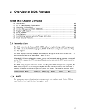
... 64 3.4 System Management BIOS (SMBIOS 65 3.5 Legacy USB Support...65 3.6 BIOS Updates ...66 3.7 Boot Options ...67 3.8 Fast Booting Systems with Intel® Rapid BIOS Boot 68 3.9 BIOS Security Features 69 3.1 Introduction The BIOS is in configure mode. 63 The BIOS Setup program is shown below...configuration utility, and Plug and Play support. Section 2.9.2 on page 51 shows how to put the board in configure mode. Maintenance Main Advanced Security Power Boot Exit NOTE The maintenance menu is displayed only when the board is stored in the BIOS and reports if...
... 64 3.4 System Management BIOS (SMBIOS 65 3.5 Legacy USB Support...65 3.6 BIOS Updates ...66 3.7 Boot Options ...67 3.8 Fast Booting Systems with Intel® Rapid BIOS Boot 68 3.9 BIOS Security Features 69 3.1 Introduction The BIOS is in configure mode. 63 The BIOS Setup program is shown below...configuration utility, and Plug and Play support. Section 2.9.2 on page 51 shows how to put the board in configure mode. Maintenance Main Advanced Security Power Boot Exit NOTE The maintenance menu is displayed only when the board is stored in the BIOS and reports if...
D865PCK Technical Product Specification
Page 64
... for menu screens. Table 37. Table 36. Any interrupts set to optimize capacity and performance. Intel Desktop Board D865PCK Technical Product Specification Table 36 lists the BIOS Setup program menu features. The IDE interface supports hard... drives up the PCI IDE connector with independent I /O space, and other system resources. To take advantage of each drive and configures them to Available in cards. BIOS Setup Program Menu Bar Maintenance Main...
... for menu screens. Table 37. Table 36. Any interrupts set to optimize capacity and performance. Intel Desktop Board D865PCK Technical Product Specification Table 36 lists the BIOS Setup program menu features. The IDE interface supports hard... drives up the PCI IDE connector with independent I /O space, and other system resources. To take advantage of each drive and configures them to Available in cards. BIOS Setup Program Menu Bar Maintenance Main...
D865PCK Technical Product Specification
Page 65
... same IDE cable as third-party management software to use a USB keyboard to enter and configure the BIOS Setup program and the maintenance menu. 4. The main component of the drive. You can obtain the system types, capabilities, operational status, and installation dates for accessing this support, an SMBIOS service-level application...
... same IDE cable as third-party management software to use a USB keyboard to enter and configure the BIOS Setup program and the maintenance menu. 4. The main component of the drive. You can obtain the system types, capabilities, operational status, and installation dates for accessing this support, an SMBIOS service-level application...

English Product Guide
Page 5
Contents 1 Desktop Board Features Supported Operating Systems 10 Desktop Board Components 11 Processor ...13 Main Memory ...14 Intel® 865P Chipset...15 Graphics Subsystem ...15 Audio Subsystem ...15 LAN Subsystem ...15 LAN Subsystem Software 15 RJ-45 LAN Connector LEDs 16 Input/Output (I/O) ...
Contents 1 Desktop Board Features Supported Operating Systems 10 Desktop Board Components 11 Processor ...13 Main Memory ...14 Intel® 865P Chipset...15 Graphics Subsystem ...15 Audio Subsystem ...15 LAN Subsystem ...15 LAN Subsystem Software 15 RJ-45 LAN Connector LEDs 16 Input/Output (I/O) ...
English Product Guide
Page 9
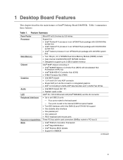
...Four ports routed to six USB 2.0 ports - Table 1 summarizes these features. Table 1. 1 Desktop Board Features This chapter describes the main features of : • Intel® 82865P Memory Controller Hub (MCH) with Ultra DMA-33 and ATA-66/100 support • One diskette drive interface •... Dual channel 333/266 MHz DDR SDRAM interface • Designed to support up to 2 GB of system memory Intel® 865P chipset consisting of Intel® Desktop Board D865PCK. Two ports routed to the internal USB front panel header • Two IDE interfaces with Accelerated Hub Architecture ...
...Four ports routed to six USB 2.0 ports - Table 1 summarizes these features. Table 1. 1 Desktop Board Features This chapter describes the main features of : • Intel® 82865P Memory Controller Hub (MCH) with Ultra DMA-33 and ATA-66/100 support • One diskette drive interface •... Dual channel 333/266 MHz DDR SDRAM interface • Designed to support up to 2 GB of system memory Intel® 865P chipset consisting of Intel® Desktop Board D865PCK. Two ports routed to the internal USB front panel header • Two IDE interfaces with Accelerated Hub Architecture ...

English Product Guide
Page 12
Intel Desktop Board D865PCK Product Guide Table 2. Item A B C D E F G H I J K L M N O P Q R S T U V W Desktop Board Components Description ATAPI CD-ROM connector Front panel audio header AGP connector Rear chassis fan header 12 V processor core voltage connector Processor socket Processor fan header Intel 82865P (MCH) DIMM sockets Main power connector Diskette drive connector Primary IDE connector Secondary IDE connector Front chassis...
Intel Desktop Board D865PCK Product Guide Table 2. Item A B C D E F G H I J K L M N O P Q R S T U V W Desktop Board Components Description ATAPI CD-ROM connector Front panel audio header AGP connector Rear chassis fan header 12 V processor core voltage connector Processor socket Processor fan header Intel 82865P (MCH) DIMM sockets Main power connector Diskette drive connector Primary IDE connector Secondary IDE connector Front chassis...
English Product Guide
Page 14
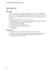
...DIMMs) connectors with DIMMs that support the Serial Presence Detect (SPD) data structure. Intel Desktop Board D865PCK Product Guide Main Memory NOTE To be fully compliant with all applicable Intel® SDRAM memory specification addendums, the board should be populated with gold-plated contacts...the memory controller for more information about: • The latest list of tested memory, http://support.intel.com/support/motherboards/desktop/ • SDRAM specifications, http://www.intel.com/technology/memory/pcsdram/spec/ • Installing memory, page 28 in this manual for normal ...
...DIMMs) connectors with DIMMs that support the Serial Presence Detect (SPD) data structure. Intel Desktop Board D865PCK Product Guide Main Memory NOTE To be fully compliant with all applicable Intel® SDRAM memory specification addendums, the board should be populated with gold-plated contacts...the memory controller for more information about: • The latest list of tested memory, http://support.intel.com/support/motherboards/desktop/ • SDRAM specifications, http://www.intel.com/technology/memory/pcsdram/spec/ • Installing memory, page 28 in this manual for normal ...

English Product Guide
Page 28
... 0 Figure 7. You can access the PC Serial Presence Detect Specification at: http://www.intel.com/technology/memory/pcsdram/spec/ Desktop Board D865PCK has two 184-pin DIMM sockets arranged as Channel A and Channel B, as shown in Figure 7. Refer to the "Main Memory" section on page 14 for memory requirements. Installing a DIMM OM17404 28
... 0 Figure 7. You can access the PC Serial Presence Detect Specification at: http://www.intel.com/technology/memory/pcsdram/spec/ Desktop Board D865PCK has two 184-pin DIMM sockets arranged as Channel A and Channel B, as shown in Figure 7. Refer to the "Main Memory" section on page 14 for memory requirements. Installing a DIMM OM17404 28

English Product Guide
Page 35
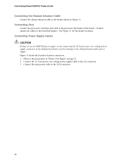
A 1 B 1 2 C 1 F 1 2 1 E Item A B C D E F D Description Chassis rear fan 12 V processor core voltage connector Processor fan Main power connector Chassis front fan Chassis intrusion header OM17407 Figure 11. Location of the chassis intrusion and fan headers, and power connectors. Installing and Replacing Desktop Board Components Connecting Hardware Control and Power Cables Figure 11 shows the location of Hardware Control Headers and Power Connectors 35
A 1 B 1 2 C 1 F 1 2 1 E Item A B C D E F D Description Chassis rear fan 12 V processor core voltage connector Processor fan Main power connector Chassis front fan Chassis intrusion header OM17407 Figure 11. Location of the chassis intrusion and fan headers, and power connectors. Installing and Replacing Desktop Board Components Connecting Hardware Control and Power Cables Figure 11 shows the location of Hardware Control Headers and Power Connectors 35
English Product Guide
Page 36
...power supply, or not connecting the 12 V processor core voltage power supply connector to the desktop board may result in Figure 11. Connect the main power cable to the desktop board and/or power supply. Connecting Fans Connect the processor's fan heat sink cable to the header shown in ...damage to the 2x10 connector. 36 Intel Desktop Board D865PCK Product Guide Connecting the Chassis Intrusion Cable Connect the chassis intrusion cable to the processor fan header on page 21. 2.
...power supply, or not connecting the 12 V processor core voltage power supply connector to the desktop board may result in Figure 11. Connect the main power cable to the desktop board and/or power supply. Connecting Fans Connect the processor's fan heat sink cable to the header shown in ...damage to the 2x10 connector. 36 Intel Desktop Board D865PCK Product Guide Connecting the Chassis Intrusion Cable Connect the chassis intrusion cable to the processor fan header on page 21. 2.