
D865PCK Technical Product Specification
Page 5
... Description 1.1 Overview ...10 1.1.1 Feature Summary 10 1.1.2 Board Layout 11 1.1.3 Block Diagram 12 1.2 Online Support ...13 1.3 Processor ...13 1.4 System Memory ...14 1.4.1 Memory Configurations 16 1.5 Intel® 865P Chipset...18 1.5.1 Universal 0.8 V / 1.5 V AGP 3.0 Connector 18 1.5.2 USB ...19 1.5.3 IDE Support ... Realtek ALC202-based Audio Subsystem 22 1.7.2 Audio Connectors 22 1.7.3 Audio Subsystem Software 23 1.8 LAN Subsystem ...23 1.8.1 Intel® 82562EZ Physical Layer Interface Device 23 1.8.2 RJ-45 LAN Connector with Integrated LEDs 24 1.8.3 LAN Subsystem Software ...
... Description 1.1 Overview ...10 1.1.1 Feature Summary 10 1.1.2 Board Layout 11 1.1.3 Block Diagram 12 1.2 Online Support ...13 1.3 Processor ...13 1.4 System Memory ...14 1.4.1 Memory Configurations 16 1.5 Intel® 865P Chipset...18 1.5.1 Universal 0.8 V / 1.5 V AGP 3.0 Connector 18 1.5.2 USB ...19 1.5.3 IDE Support ... Realtek ALC202-based Audio Subsystem 22 1.7.2 Audio Connectors 22 1.7.3 Audio Subsystem Software 23 1.8 LAN Subsystem ...23 1.8.1 Intel® 82562EZ Physical Layer Interface Device 23 1.8.2 RJ-45 LAN Connector with Integrated LEDs 24 1.8.3 LAN Subsystem Software ...
D865PCK Technical Product Specification
Page 7
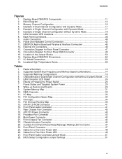
... Example of Single Channel Configuration with Dynamic Mode 17 5. Connection Diagram for a Two-Color Power LED 48 27. Desktop Board D865PCK Dimensions 52 17. Supported System Bus Frequency and Memory Speed Combinations 14 3. DMA Channels ...32 11. Rear Chassis Fan Connector 43...Panel Connectors 38 9. External I /O Map ...32 12. System Memory Map 31 10. Interrupts ...34 14. ATX12V Power Connector 43 19. Processor Fan Connector 43 20. Front Panel Connector 47 25. States for Front Panel Connector 47 14. Audio Connectors...40 10. Supported Memory Configurations ...
... Example of Single Channel Configuration with Dynamic Mode 17 5. Connection Diagram for a Two-Color Power LED 48 27. Desktop Board D865PCK Dimensions 52 17. Supported System Bus Frequency and Memory Speed Combinations 14 3. DMA Channels ...32 11. Rear Chassis Fan Connector 43...Panel Connectors 38 9. External I /O Map ...32 12. System Memory Map 31 10. Interrupts ...34 14. ATX12V Power Connector 43 19. Processor Fan Connector 43 20. Front Panel Connector 47 25. States for Front Panel Connector 47 14. Audio Connectors...40 10. Supported Memory Configurations ...
D865PCK Technical Product Specification
Page 9
1 Product Description What This Chapter Contains 1.1 Overview ...10 1.2 Online Support ...13 1.3 Processor ...13 1.4 System Memory ...14 1.5 Intel® 865P Chipset...18 1.6 I/O Controller...20 1.7 Audio Subsystem ...22 1.8 LAN Subsystem ...23 1.9 Chassis Intrusion and Detection 24 1.10 Power Management ...24 9
1 Product Description What This Chapter Contains 1.1 Overview ...10 1.2 Online Support ...13 1.3 Processor ...13 1.4 System Memory ...14 1.5 Intel® 865P Chipset...18 1.6 I/O Controller...20 1.7 Audio Subsystem ...22 1.8 LAN Subsystem ...23 1.9 Chassis Intrusion and Detection 24 1.10 Power Management ...24 9
D865PCK Technical Product Specification
Page 10
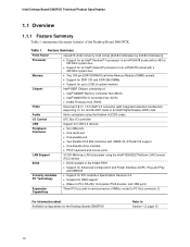
... connector 2) For information about Available configurations for the Desktop Boards D865PCK Refer to Section 1.2, page 13 10 Table 1. Feature Summary Form Factor microATX (9.60 inches by 9.60 inches [243.84 millimeters by 243.84 millimeters]) Processor • Support for an Intel® Pentium® 4 processor in an mPGA478 socket with a 400 or 533 MHz...
... connector 2) For information about Available configurations for the Desktop Boards D865PCK Refer to Section 1.2, page 13 10 Table 1. Feature Summary Form Factor microATX (9.60 inches by 9.60 inches [243.84 millimeters by 243.84 millimeters]) Processor • Support for an Intel® Pentium® 4 processor in an mPGA478 socket with a 400 or 533 MHz...
D865PCK Technical Product Specification
Page 11
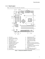
...Ethernet PLC device (optional) D AGP connector E Rear chassis fan connector F Back panel connectors G +12V power connector (ATX12V) H mPGA478 processor socket I Processor fan connector J Intel 82865P MCH K DIMM Channel A socket L DIMM Channel B socket M I/O controller N Power connector OM17040 O Diskette drive connector P Parallel ... X Intel 82801EB I/O Controller Hub (ICH5) Y Front panel USB connector Z Battery AA PCI bus add-in card connectors BB ATAPI CD-ROM connector Figure 1. 1.1.2 Board Layout Figure 1 shows the location of the major components. Desktop Board D865PCK Components 11...
...Ethernet PLC device (optional) D AGP connector E Rear chassis fan connector F Back panel connectors G +12V power connector (ATX12V) H mPGA478 processor socket I Processor fan connector J Intel 82865P MCH K DIMM Channel A socket L DIMM Channel B socket M I/O controller N Power connector OM17040 O Diskette drive connector P Parallel ... X Intel 82801EB I/O Controller Hub (ICH5) Y Front panel USB connector Z Battery AA PCI bus add-in card connectors BB ATAPI CD-ROM connector Figure 1. 1.1.2 Board Layout Figure 1 shows the location of the major components. Desktop Board D865PCK Components 11...
D865PCK Technical Product Specification
Page 12
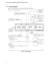
Block Diagram OM17554 12 Intel Desktop Board D865PCK Technical Product Specification 1.1.3 Block Diagram Figure 2 is a block diagram of the major functional areas of the board. = connector or socket Parallel ATA IDE Connectors (2) Parallel ATA IDE Interface mPGA478 Processor Socket System Bus (400/533 MHz) USB LPC Bus I/O Controller LPC Bus Back Panel/ Front Panel...
Block Diagram OM17554 12 Intel Desktop Board D865PCK Technical Product Specification 1.1.3 Block Diagram Figure 2 is a block diagram of the major functional areas of the board. = connector or socket Parallel ATA IDE Connectors (2) Parallel ATA IDE Interface mPGA478 Processor Socket System Bus (400/533 MHz) USB LPC Bus I/O Controller LPC Bus Back Panel/ Front Panel...
D865PCK Technical Product Specification
Page 13
...boot. • Do not use a standard ATX power supply. Intel® Desktop Board D865PCK under "Desktop Board Products" or "Desktop Board Support" Available configurations for the Desktop Board D865PCK Processor data sheets ICH5 addressing Custom splash screens Audio software and utilities ...LAN software and drivers Visit this Intel desktop board. Supported processors for the D865PCK board Refer to Table 2 on web site above ...
...boot. • Do not use a standard ATX power supply. Intel® Desktop Board D865PCK under "Desktop Board Products" or "Desktop Board Support" Available configurations for the Desktop Board D865PCK Processor data sheets ICH5 addressing Custom splash screens Audio software and utilities ...LAN software and drivers Visit this Intel desktop board. Supported processors for the D865PCK board Refer to Table 2 on web site above ...
D865PCK Technical Product Specification
Page 14
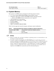
... 2. If non-SPD memory is installed, the BIOS will attempt to accurately configure memory settings for optimum performance. The processor's system bus frequency must be... This allows the BIOS to read the SPD data and program the chipset to correctly ...sided DIMMs with the following restriction: ⎯ Double-sided DIMMS with DIMMs that support the Serial Presence Detect (SPD) data structure. Intel Desktop Board D865PCK Technical Product Specification For information about Power supply connectors Refer to avoid interference with the memory retention mechanism. • To be fully...
... 2. If non-SPD memory is installed, the BIOS will attempt to accurately configure memory settings for optimum performance. The processor's system bus frequency must be... This allows the BIOS to read the SPD data and program the chipset to correctly ...sided DIMMs with the following restriction: ⎯ Double-sided DIMMS with DIMMs that support the Serial Presence Detect (SPD) data structure. Intel Desktop Board D865PCK Technical Product Specification For information about Power supply connectors Refer to avoid interference with the memory retention mechanism. • To be fully...
D865PCK Technical Product Specification
Page 20
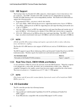
... cable to the BIOS. NOTE If the battery and AC power fail, custom defaults, if previously saved, will be independently enabled. Intel Desktop Board D865PCK Technical Product Specification 1.5.3 IDE Support The board provides two Parallel ATA IDE connectors, which support a total of the Parallel ATA IDE ...DMA and is accurate to ± 13 minutes/year at power-on. 1.6 I/O Controller The I /O (PIO): processor controls data transfer. • 8237-style DMA: DMA offloads the processor, supporting transfer rates of up to 16 MB/sec. • Ultra DMA: DMA protocol on IDE bus supporting host...
... cable to the BIOS. NOTE If the battery and AC power fail, custom defaults, if previously saved, will be independently enabled. Intel Desktop Board D865PCK Technical Product Specification 1.5.3 IDE Support The board provides two Parallel ATA IDE connectors, which support a total of the Parallel ATA IDE ...DMA and is accurate to ± 13 minutes/year at power-on. 1.6 I/O Controller The I /O (PIO): processor controls data transfer. • 8237-style DMA: DMA offloads the processor, supporting transfer rates of up to 16 MB/sec. • Ultra DMA: DMA protocol on IDE bus supporting host...
D865PCK Technical Product Specification
Page 26
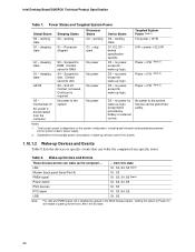
... Modem (back panel Serial Port A) PME# signal Power switch PS/2 devices RTC alarm USB ...from the computer. sleeping state G2/S5 G3 - working state G1 - Processor States C0 - D3 - D3 - stop grant No power No power No power Device States D0 - Targeted System Power (Note 1) Full power > 30 W 5 W < power < 52.5 W .... sleeping state G1 - mechanical off . working S1 - Suspend to disk. no power for wake-up Devices and Events These devices/events can be performed safely. Intel Desktop Board D865PCK Technical Product Specification Table 7. No power to the system.
... Modem (back panel Serial Port A) PME# signal Power switch PS/2 devices RTC alarm USB ...from the computer. sleeping state G2/S5 G3 - working state G1 - Processor States C0 - D3 - D3 - stop grant No power No power No power Device States D0 - Targeted System Power (Note 1) Full power > 30 W 5 W < power < 52.5 W .... sleeping state G1 - mechanical off . working S1 - Suspend to disk. no power for wake-up Devices and Events These devices/events can be performed safely. Intel Desktop Board D865PCK Technical Product Specification Table 7. No power to the system.
D865PCK Technical Product Specification
Page 39
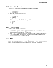
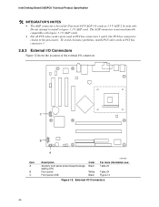
The AGP connector is routed to processor location on the Desktop Board. Figure 11 (page 45) illustrates the board's PCI slot numbering. 39 PCI slots are divided into the following functional groups: &#... the following expansion slots: • AGP connector: The AGP connector is not numbered. The SMBus is not mechanically compatible with the slot closest to the processor. The AGP slot is keyed for Universal 0.8 V AGP 3.0 cards or 1.5 V AGP 2.0 cards only.
The AGP connector is routed to processor location on the Desktop Board. Figure 11 (page 45) illustrates the board's PCI slot numbering. 39 PCI slots are divided into the following functional groups: &#... the following expansion slots: • AGP connector: The AGP connector is not numbered. The SMBus is not mechanically compatible with the slot closest to the processor. The AGP slot is keyed for Universal 0.8 V AGP 3.0 cards or 1.5 V AGP 2.0 cards only.
D865PCK Technical Product Specification
Page 42
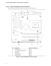
Intel Desktop Board D865PCK Technical Product Specification 2.8.2.3 Power and Hardware Control Connectors Figure 10 shows the location of the power and hardware control connectors. Power and Hardware Control Connectors OM17036 42 A B 1 3 12 34 1 3 113 20 11 1 FE D C Item A B C D E F Description Rear chassis fan +12 V power connector (ATX12V) Processor fan Main power Front chassis fan Chassis intrusion For more information see: Table 17 Table 18 Table 19 Table 20 Table 21 Table 22 Figure 10.
Intel Desktop Board D865PCK Technical Product Specification 2.8.2.3 Power and Hardware Control Connectors Figure 10 shows the location of the power and hardware control connectors. Power and Hardware Control Connectors OM17036 42 A B 1 3 12 34 1 3 113 20 11 1 FE D C Item A B C D E F Description Rear chassis fan +12 V power connector (ATX12V) Processor fan Main power Front chassis fan Chassis intrusion For more information see: Table 17 Table 18 Table 19 Table 20 Table 21 Table 22 Figure 10.
D865PCK Technical Product Specification
Page 43
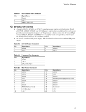
ATX12V, SFX12V, and TFX12V power supplies have an additional power lead that provides required supplemental power for the processor. ATX12V Power Connector Pin Signal Name 1 Ground 3 +12 V Pin Signal Name 2 Ground 4 +...on /off) 15 Ground 16 Ground 17 Ground 18 No connect 19 +5 V 20 +5 V 43 Technical Reference Table 17. Table 18. Processor Fan Connector Pin Signal Name 1 Control 2 +12 V 3 CPU_FAN_TACH Table 20. Rear Chassis Fan Connector Pin Signal Name 1 Control 2 +...the desktop board, otherwise the board will not boot with the Desktop Board D865PCK.
ATX12V, SFX12V, and TFX12V power supplies have an additional power lead that provides required supplemental power for the processor. ATX12V Power Connector Pin Signal Name 1 Ground 3 +12 V Pin Signal Name 2 Ground 4 +...on /off) 15 Ground 16 Ground 17 Ground 18 No connect 19 +5 V 20 +5 V 43 Technical Reference Table 17. Table 18. Processor Fan Connector Pin Signal Name 1 Control 2 +12 V 3 CPU_FAN_TACH Table 20. Rear Chassis Fan Connector Pin Signal Name 1 Control 2 +...the desktop board, otherwise the board will not boot with the Desktop Board D865PCK.
D865PCK Technical Product Specification
Page 46
Do not attempt to the processor). The AGP connector is keyed for Universal 0.8 V AGP 3.0 cards or 1.5 V AGP 2.0 cards only. Intel Desktop Board D865PCK Technical Product Specification # INTEGRATOR'S NOTES • The AGP connector is not mechanically compatible with legacy 3.3 V AGP cards. • Not all PCI video cards can be ...
Do not attempt to the processor). The AGP connector is keyed for Universal 0.8 V AGP 3.0 cards or 1.5 V AGP 2.0 cards only. Intel Desktop Board D865PCK Technical Product Specification # INTEGRATOR'S NOTES • The AGP connector is not mechanically compatible with legacy 3.3 V AGP cards. • Not all PCI video cards can be ...
D865PCK Technical Product Specification
Page 51
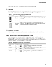
When the jumper is set to configure mode and the computer is required. 51 Table 27. A 3 recovery diskette is powered-up, the BIOS compares the processor version and the microcode version in the BIOS and reports if the two match. Technical Reference Table 27 describes the two configurations of the signals ...
When the jumper is set to configure mode and the computer is required. 51 Table 27. A 3 recovery diskette is powered-up, the BIOS compares the processor version and the microcode version in the BIOS and reports if the two match. Technical Reference Table 27 describes the two configurations of the signals ...
D865PCK Technical Product Specification
Page 54
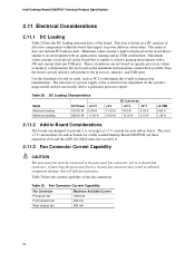
...These calculations are not based on a DC analysis of +5 V current for a fully loaded Desktop Board D865PCK (all active components within the board that is based on specific processor values or memory configurations but are designed to provide 2 A (average) of all three expansion slots and...to the processor, memory, and USB ports. Minimum values assume a light load placed on the board that impact its power delivery subsystems. The analysis does not include PCI add-in board. This data is similar to a chassis fan connector. Intel Desktop Board D865PCK Technical Product ...
...These calculations are not based on a DC analysis of +5 V current for a fully loaded Desktop Board D865PCK (all active components within the board that is based on specific processor values or memory configurations but are designed to provide 2 A (average) of all three expansion slots and...to the processor, memory, and USB ports. Minimum values assume a light load placed on the board that impact its power delivery subsystems. The analysis does not include PCI add-in board. This data is similar to a chassis fan connector. Intel Desktop Board D865PCK Technical Product ...
D865PCK Technical Product Specification
Page 55
... result in Table 29 when selecting a power supply for use of an Intel Pentium 4 processor operating above 2.80 GHz Failure to ensure appropriate airflow may result in reduced performance of both the processor and/or voltage regulator or, in some instances, damage to the desktop ...appropriate airflow to ensure proper cooling of the components on the board • A processor fan heatsink that have been tested with Intel desktop boards please refer to the following website: http://developer.intel.com/design/motherbd/cooling.htm All responsibility for determining the adequacy of any thermal or...
... result in Table 29 when selecting a power supply for use of an Intel Pentium 4 processor operating above 2.80 GHz Failure to ensure appropriate airflow may result in reduced performance of both the processor and/or voltage regulator or, in some instances, damage to the desktop ...appropriate airflow to ensure proper cooling of the components on the board • A processor fan heatsink that have been tested with Intel desktop boards please refer to the following website: http://developer.intel.com/design/motherbd/cooling.htm All responsibility for determining the adequacy of any thermal or...
D865PCK Technical Product Specification
Page 56
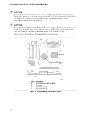
... D Item A B C D Description Processor voltage regulator area Processor Intel 82865P MCH Intel 82801EB ICH5 OM17041 Figure 18. Localized High Temperature Zones 56 Intel Desktop Board D865PCK Technical Product Specification CAUTION Ensure that proper airflow is maintained in the processor voltage regulator circuit. For information about the... circuit. CAUTION Ensure that the ambient temperature does not exceed the Desktop Board's maximum operating temperature. The processor voltage regulator area (item A in Figure 18) can reach a temperature of the localized high temperature zones...
... D Item A B C D Description Processor voltage regulator area Processor Intel 82865P MCH Intel 82801EB ICH5 OM17041 Figure 18. Localized High Temperature Zones 56 Intel Desktop Board D865PCK Technical Product Specification CAUTION Ensure that proper airflow is maintained in the processor voltage regulator circuit. For information about the... circuit. CAUTION Ensure that the ambient temperature does not exceed the Desktop Board's maximum operating temperature. The processor voltage regulator area (item A in Figure 18) can reach a temperature of the localized high temperature zones...
D865PCK Technical Product Specification
Page 57
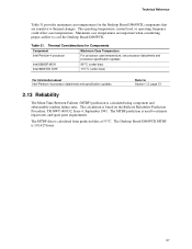
... maximum case temperatures for Components Component Intel Pentium 4 processor Intel 82865P MCH Intel 82801EB ICH5 Maximum Case Temperature For processor case temperature, see processor datasheets and processor specification updates 99 oC (under bias) 115 oC (under bias) For information about Intel Pentium 4 processor datasheets and specification updates Refer to cool the Desktop Board D865PCK. The MTBF prediction is used to...
... maximum case temperatures for Components Component Intel Pentium 4 processor Intel 82865P MCH Intel 82801EB ICH5 Maximum Case Temperature For processor case temperature, see processor datasheets and processor specification updates 99 oC (under bias) 115 oC (under bias) For information about Intel Pentium 4 processor datasheets and specification updates Refer to cool the Desktop Board D865PCK. The MTBF prediction is used to...
D865PCK Technical Product Specification
Page 64
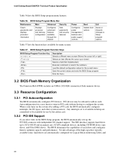
... on the system after adding a PCI card, the BIOS automatically configures interrupts, the I /O channel support. Intel Desktop Board D865PCK Technical Product Specification Table 36 lists the BIOS Setup program menu features. PCI devices may be available for Logical Block... Addressing (LBA) and 64 BIOS Setup Program Menu Bar Maintenance Main Advanced Security Clears passwords and displays processor information Displays processor...
... on the system after adding a PCI card, the BIOS automatically configures interrupts, the I /O channel support. Intel Desktop Board D865PCK Technical Product Specification Table 36 lists the BIOS Setup program menu features. PCI devices may be available for Logical Block... Addressing (LBA) and 64 BIOS Setup Program Menu Bar Maintenance Main Advanced Security Clears passwords and displays processor information Displays processor...


