
Product Specification
Page 6
... PCI IDE Support 79 3.4 System Management BIOS (SMBIOS 79 3.5 Legacy USB Support 80 3.6 BIOS Updates 80 3.6.1 Language Support 81 3.6.2 Custom Splash Screen 81 3.7 Boot Options 81 3.7.1 CD-ROM Boot 81 3.7.2 Network Boot 81 3.7.3 Booting Without Attached Devices 82 3.7.4 Changing the Default Boot Device During POST 82 3.8 Fast Booting Systems with Intel® Rapid BIOS Boot 82 3.8.1 Peripheral Selection and Configuration 82 3.8.2 Intel Rapid BIOS Boot 83 3.9 BIOS Security Features 84 4 Error Messages and Beep Codes 4.1 BIOS Error Messages 85 4.2 Port 80h POST Codes 86 4.3 Bus...
... PCI IDE Support 79 3.4 System Management BIOS (SMBIOS 79 3.5 Legacy USB Support 80 3.6 BIOS Updates 80 3.6.1 Language Support 81 3.6.2 Custom Splash Screen 81 3.7 Boot Options 81 3.7.1 CD-ROM Boot 81 3.7.2 Network Boot 81 3.7.3 Booting Without Attached Devices 82 3.7.4 Changing the Default Boot Device During POST 82 3.8 Fast Booting Systems with Intel® Rapid BIOS Boot 82 3.8.1 Peripheral Selection and Configuration 82 3.8.2 Intel Rapid BIOS Boot 83 3.9 BIOS Security Features 84 4 Error Messages and Beep Codes 4.1 BIOS Error Messages 85 4.2 Port 80h POST Codes 86 4.3 Bus...

Product Specification
Page 7
... Mode 18 6. LAN Connector LED Locations 38 8. Location of Dual Channel Configuration with Dynamic Mode 19 5. Back Panel Connectors 53 11. Connection Diagram for Front Panel Connector 59 13. Supported System Bus Frequency and Memory Speed Combinations 16 4. Wake-up Devices and Events 43 15. Component-side Connectors Shown in Figure 1 13 3. Connection Diagram for Front Panel USB Connectors 60 14. I /O Map ...48 17. PCI Configuration Space Map 49 18. Front Panel Audio Connector 57 vii Major Board Components 12 2. Example of the Standby Power Indicator LED...
... Mode 18 6. LAN Connector LED Locations 38 8. Location of Dual Channel Configuration with Dynamic Mode 19 5. Back Panel Connectors 53 11. Connection Diagram for Front Panel Connector 59 13. Supported System Bus Frequency and Memory Speed Combinations 16 4. Wake-up Devices and Events 43 15. Component-side Connectors Shown in Figure 1 13 3. Connection Diagram for Front Panel USB Connectors 60 14. I /O Map ...48 17. PCI Configuration Space Map 49 18. Front Panel Audio Connector 57 vii Major Board Components 12 2. Example of the Standby Power Indicator LED...

Product Specification
Page 8
.... Lead-Free Board Markings 74 40. BIOS Setup Configuration Jumper Settings 61 34. Desktop Board D865GSA Environmental Specifications 69 38. Uncompressed INIT Code Checkpoints 87 48. Beep Codes 93 viii States for a One-Color Power LED 59 32. Safety Regulations 70 39. Product Certification Markings 76 42. BIOS Setup Program Menu Bar 78 43. Intel Desktop Board D865GSA Technical Product Specification 28. Lower Nibble High Byte Functions 92 53. Boot Device Menu Options 82 45. Front Panel Connector 58 31. BIOS Error Messages...
.... Lead-Free Board Markings 74 40. BIOS Setup Configuration Jumper Settings 61 34. Desktop Board D865GSA Environmental Specifications 69 38. Uncompressed INIT Code Checkpoints 87 48. Beep Codes 93 viii States for a One-Color Power LED 59 32. Safety Regulations 70 39. Product Certification Markings 76 42. BIOS Setup Program Menu Bar 78 43. Intel Desktop Board D865GSA Technical Product Specification 28. Lower Nibble High Byte Functions 92 53. Boot Device Menu Options 82 45. Front Panel Connector 58 31. BIOS Error Messages...

Product Specification
Page 58
... access sensor data on the board. Intel Desktop Board D865GSA Technical Product Specification 2.7.2.2 Add-in Card Connectors The board has the following considerations for the front panel connector. PCI Conventional bus add-in cards with SMBus support to PCI Conventional bus connector 2 only (ATX expansion slot 6). The specific SMBus signals are routed to +5 V 3 HDA# Out Hard disk active LED Reset Switch 5 Ground 7 FP_RESET# In Ground Reset switch Power 9 +5 V Power Pin 2 4 6 8 10 Signal In/ Out Description Power LED HDR_BLNK_GRN Out Front panel green LED...
... access sensor data on the board. Intel Desktop Board D865GSA Technical Product Specification 2.7.2.2 Add-in Card Connectors The board has the following considerations for the front panel connector. PCI Conventional bus add-in cards with SMBus support to PCI Conventional bus connector 2 only (ATX expansion slot 6). The specific SMBus signals are routed to +5 V 3 HDA# Out Hard disk active LED Reset Switch 5 Ground 7 FP_RESET# In Ground Reset switch Power 9 +5 V Power Pin 2 4 6 8 10 Signal In/ Out Description Power LED HDR_BLNK_GRN Out Front panel green LED...

Product Specification
Page 77
... system boot begins. When the BIOS Setup configuration jumper is in configure mode. 77 The BIOS Setup program is shown below. The initial production BIOSs are identified as SA86510A.86A. Maintenance Main Advanced Security Power Boot Exit NOTE The maintenance menu is displayed only when the board is set to put the board in configure mode. 3 Overview of BIOS and a revision code. The FWH contains the BIOS Setup program, POST, the PCI auto-configuration utility, and Plug and Play support.
... system boot begins. When the BIOS Setup configuration jumper is in configure mode. 77 The BIOS Setup program is shown below. The initial production BIOSs are identified as SA86510A.86A. Maintenance Main Advanced Security Power Boot Exit NOTE The maintenance menu is displayed only when the board is set to put the board in configure mode. 3 Overview of BIOS and a revision code. The FWH contains the BIOS Setup program, POST, the PCI auto-configuration utility, and Plug and Play support.

Product Specification
Page 78
... The BIOS can automatically configure PCI devices. BIOS Setup Program Menu Bar Maintenance Main Advanced Security Power Boot Exit Clears passwords and displays processor information Displays processor and memory configuration Configures advanced features available through the chipset Sets Configures Selects boot Saves or passwords power options discards and security manage- PCI devices may be available for use by the add-in cards. Table 42. BIOS Setup Program Function Keys BIOS Setup Program Function Key Description or or Selects a different menu screen (Moves...
... The BIOS can automatically configure PCI devices. BIOS Setup Program Menu Bar Maintenance Main Advanced Security Power Boot Exit Clears passwords and displays processor information Displays processor and memory configuration Configures advanced features available through the chipset Sets Configures Selects boot Saves or passwords power options discards and security manage- PCI devices may be available for use by the add-in cards. Table 42. BIOS Setup Program Function Keys BIOS Setup Program Function Key Description or or Selects a different menu screen (Moves...

Product Specification
Page 79
... high capacities typically available today, hard drives are required: • An ATA-66/100 peripheral device • An ATA-66/100 compatible cable • ATA-66/100 operating system device drivers NOTE Do not connect an ATA device as Windows NT*, require an additional interface for managing computers in a managed network. You can override the auto-configuration options by specifying manual configuration in the BIOS Setup program, the BIOS automatically sets...
... high capacities typically available today, hard drives are required: • An ATA-66/100 peripheral device • An ATA-66/100 compatible cable • ATA-66/100 operating system device drivers NOTE Do not connect an ATA device as Windows NT*, require an additional interface for managing computers in a managed network. You can override the auto-configuration options by specifying manual configuration in the BIOS Setup program, the BIOS automatically sets...

Product Specification
Page 80
... BIOS. Intel Desktop Board D865GSA Technical Product Specification 3.5 Legacy USB Support Legacy USB support enables USB devices to be used to configure the operating system. (Keyboards and mice are not recognized during this period if Legacy USB support was set to Disabled in the BIOS Setup program.) 6. Legacy USB support operates as follows: 1. Using this utility, the BIOS can be updated from a file on a 1.44 MB diskette (from the file location on the Intel World Wide Web site: • Intel® Express BIOS Update utility, which requires creation of a boot diskette and manual...
... BIOS. Intel Desktop Board D865GSA Technical Product Specification 3.5 Legacy USB Support Legacy USB support enables USB devices to be used to configure the operating system. (Keyboards and mice are not recognized during this period if Legacy USB support was set to Disabled in the BIOS Setup program.) 6. Legacy USB support operates as follows: 1. Using this utility, the BIOS can be updated from a file on a 1.44 MB diskette (from the file location on the Intel World Wide Web site: • Intel® Express BIOS Update utility, which requires creation of a boot diskette and manual...

Product Specification
Page 86
... installed in the tables because that code applies to be bad. Memory size has changed since the last boot. No Boot Device Available System did not find a device to access hard disk controller. Updated Failed NVRAM was invalid but was added there may be updated. KB/Interface Error Keyboard interface test failed. If no memory was removed then memory may be powered down and the jumper removed. NOTE The POST card must enter Setup. 4.2 Port 80h POST Codes During the POST...
... installed in the tables because that code applies to be bad. Memory size has changed since the last boot. No Boot Device Available System did not find a device to access hard disk controller. Updated Failed NVRAM was invalid but was added there may be updated. KB/Interface Error Keyboard interface test failed. If no memory was removed then memory may be powered down and the jumper removed. NOTE The POST card must enter Setup. 4.2 Port 80h POST Codes During the POST...

Product Specification
Page 87
.... D1 Keyboard controller BAT test, CPU ID saved, and going to check point E9). 87 D3 Do necessary chipset initialization, start memory refresh, and do memory sizing. D4 Verify base memory. D7 Find Main BIOS module in segment 0. EA Try to boot sector code. D6 Control is uncompressed in F000:0000 in F000 shadow RAM. D8 Uncompress the main BIOS module. Compressed recovery code is in ROM image. EF Booting from floppy...
.... D1 Keyboard controller BAT test, CPU ID saved, and going to check point E9). 87 D3 Do necessary chipset initialization, start memory refresh, and do memory sizing. D4 Verify base memory. D7 Find Main BIOS module in segment 0. EA Try to boot sector code. D6 Control is uncompressed in F000:0000 in F000 shadow RAM. D8 Uncompress the main BIOS module. Compressed recovery code is in ROM image. EF Booting from floppy...

Product Specification
Page 88
..., static, output devices) to start if present. (See Section 4.3 for details of different buses.) 2B To give control to do any setup required before setting video mode to disable DMA and Interrupt controllers. 13 Video display is disabled and port-B is Disabled. Intel Desktop Board D865GSA Technical Product Specification Table 49. Runtime Code Uncompressed in every boot" is set or key is toggling. To do display memory R/W test. 2F EGA/VGA not found. Chipset init about to...
..., static, output devices) to start if present. (See Section 4.3 for details of different buses.) 2B To give control to do any setup required before setting video mode to disable DMA and Interrupt controllers. 13 Video display is disabled and port-B is Disabled. Intel Desktop Board D865GSA Technical Product Specification Table 49. Runtime Code Uncompressed in every boot" is set or key is toggling. To do display memory R/W test. 2F EGA/VGA not found. Chipset init about to...

Product Specification
Page 89
... keyboard reset command. 81 Keyboard reset error/stuck key found and verified. Going to clear Hit message. 59 Hit message cleared. message displayed. Clearing output buffer, checking for lock-key. To check for stuck key, to clear memory below 1M found and verified. Going to enter in real mode. 54 Shutdown successful, CPU in progress. 80 Keyboard test started . Going for memory wrap around at 0:0 and finding the total system memory size...
... keyboard reset command. 81 Keyboard reset error/stuck key found and verified. Going to clear Hit message. 59 Hit message cleared. message displayed. Clearing output buffer, checking for lock-key. To check for stuck key, to clear memory below 1M found and verified. Going to enter in real mode. 54 Shutdown successful, CPU in progress. 80 Keyboard test started . Going for memory wrap around at 0:0 and finding the total system memory size...
Product Specification
Page 92
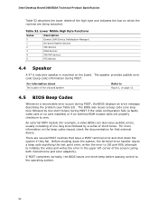
... point error, writes the error to I/O port 80h, attempts to Figure 1, on page 12 4.5 BIOS Beep Codes Whenever a recoverable error occurs during POST. There are being executed. If POST completes normally, the BIOS issues one long tone followed by a series of short tones. The BIOS also issues a beep code (one short beep before passing control to zero. Before shutting down the system if they fail. Table 52. Intel Desktop Board D865GSA Technical Product Specification...
... point error, writes the error to I/O port 80h, attempts to Figure 1, on page 12 4.5 BIOS Beep Codes Whenever a recoverable error occurs during POST. There are being executed. If POST completes normally, the BIOS issues one long tone followed by a series of short tones. The BIOS also issues a beep code (one short beep before passing control to zero. Before shutting down the system if they fail. Table 52. Intel Desktop Board D865GSA Technical Product Specification...

Product Specification
Page 93
Error Messages and Beep Codes Table 53. Beep Codes Beep Description 1 Refresh failure 2 Parity cannot be reset 3 First 64 KB memory failure 4 Timer not operational 5 Not used 6 8042 GateA20 cannot be toggled 7 Exception interrupt error 8 Display memory R/W error 9 Not used 10 CMOS Shutdown register test error 11 Invalid BIOS (e.g. POST module not found, etc.) 93
Error Messages and Beep Codes Table 53. Beep Codes Beep Description 1 Refresh failure 2 Parity cannot be reset 3 First 64 KB memory failure 4 Timer not operational 5 Not used 6 8042 GateA20 cannot be toggled 7 Exception interrupt error 8 Display memory R/W error 9 Not used 10 CMOS Shutdown register test error 11 Invalid BIOS (e.g. POST module not found, etc.) 93

Intel Desktop Board D865GSA Product Guide English
Page 6
... Card 36 Connecting the IDE Cables 37 Connecting the Serial ATA (SATA) Cable 38 Connecting Internal Headers 39 Installing a Front Panel Audio Solution 40 Connecting to the CD-ROM Audio Header 40 Connecting to the USB 2.0 Header 41 Connecting to the Front Panel Header 41 Connecting Chassis Fan and Power Cables 42 Connecting Chassis Fan Cables 42 Connecting Power Cables 43 Other Connectors...44 Setting the BIOS Configuration Jumper 45 Clearing Passwords ...46 Back Panel Connectors...47 3 Updating the BIOS Updating the BIOS with the Intel® Express BIOS Update Utility 53 Updating...
... Card 36 Connecting the IDE Cables 37 Connecting the Serial ATA (SATA) Cable 38 Connecting Internal Headers 39 Installing a Front Panel Audio Solution 40 Connecting to the CD-ROM Audio Header 40 Connecting to the USB 2.0 Header 41 Connecting to the Front Panel Header 41 Connecting Chassis Fan and Power Cables 42 Connecting Chassis Fan Cables 42 Connecting Power Cables 43 Other Connectors...44 Setting the BIOS Configuration Jumper 45 Clearing Passwords ...46 Back Panel Connectors...47 3 Updating the BIOS Updating the BIOS with the Intel® Express BIOS Update Utility 53 Updating...

Intel Desktop Board D865GSA Product Guide English
Page 9
Four ports routed to RAM (STR) • Wake on USB, PCI, RS-232, PS/2, LAN, and front panel continued 9 Four ports routed to two internal USB headers • Two IDE interfaces with Accelerated Hub Architecture (AHA) bus • Intel® 82801EB I/O Controller Hub (ICH5) • 4 Mbit Firmware Hub (FWH) • Intel 865G chipset • Integrated Intel® Extreme Graphics 2 • Support for Advanced Configuration and Power Interface (ACPI) • Suspend to the back panel - 1 Desktop Board Features This...
Four ports routed to RAM (STR) • Wake on USB, PCI, RS-232, PS/2, LAN, and front panel continued 9 Four ports routed to two internal USB headers • Two IDE interfaces with Accelerated Hub Architecture (AHA) bus • Intel® 82801EB I/O Controller Hub (ICH5) • 4 Mbit Firmware Hub (FWH) • Intel 865G chipset • Integrated Intel® Extreme Graphics 2 • Support for Advanced Configuration and Power Interface (ACPI) • Suspend to the back panel - 1 Desktop Board Features This...
Intel Desktop Board D865GSA Product Guide English
Page 12
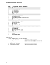
... 2 PCI bus connector 1 AGP connector Rear chassis fan header (3-pin) Back panel connectors 12 V processor core voltage connector (2 x 2 pin ) Processor socket Processor fan header (4-pin) Main power connector (2 x 12 pin) Diskette drive connector IDE connectors Chassis intrusion header Battery Serial ATA connectors Front panel header Front chassis fan header (3-pin) BIOS configuration jumper block USB 2.0 headers Speaker CD-ROM audio header Related Links: Go to the following links for more information about: • Desktop Board D865GSA http://www.intel.com/design/motherbd http://support...
... 2 PCI bus connector 1 AGP connector Rear chassis fan header (3-pin) Back panel connectors 12 V processor core voltage connector (2 x 2 pin ) Processor socket Processor fan header (4-pin) Main power connector (2 x 12 pin) Diskette drive connector IDE connectors Chassis intrusion header Battery Serial ATA connectors Front panel header Front chassis fan header (3-pin) BIOS configuration jumper block USB 2.0 headers Speaker CD-ROM audio header Related Links: Go to the following links for more information about: • Desktop Board D865GSA http://www.intel.com/design/motherbd http://support...
Intel Desktop Board D865GSA Product Guide English
Page 18
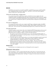
... PCI and IDE auto-configuration utilities, and the video BIOS. The BIOS is booted. PCI Auto Configuration If you can be connected to access Setup. The password prompt is displayed before the computer is stored in card. If both the supervisor and user passwords are set for the BIOS Setup and for a password. You do not need to run the BIOS Setup program after you install a PCI add-in the Serial Peripheral Interface (SPI) Flash or the Firmware Hub. Chassis Intrusion The board supports a chassis...
... PCI and IDE auto-configuration utilities, and the video BIOS. The BIOS is booted. PCI Auto Configuration If you can be connected to access Setup. The password prompt is displayed before the computer is stored in card. If both the supervisor and user passwords are set for the BIOS Setup and for a password. You do not need to run the BIOS Setup program after you install a PCI add-in the Serial Peripheral Interface (SPI) Flash or the Firmware Hub. Chassis Intrusion The board supports a chassis...

Intel Desktop Board D865GSA Product Guide English
Page 40
... Turn off all peripheral devices connected to the CD-ROM audio header, observe the precautions in "Before You Begin" on page 23. 2. Table 7. Connecting to the CD-ROM Audio Header Before connecting to the computer. Install a correctly keyed and shielded front panel audio cable. 6. Connect the audio cable to disable the back panel audio connectors. 5. Remove the front panel audio cable. 5. Intel Desktop Board D865GSA Product Guide Installing a Front Panel Audio Solution Figure 20, A on page 39 shows the location of the header. Install a jumper on pins 9-10 (rear L channel...
... Turn off all peripheral devices connected to the CD-ROM audio header, observe the precautions in "Before You Begin" on page 23. 2. Table 7. Connecting to the CD-ROM Audio Header Before connecting to the computer. Install a correctly keyed and shielded front panel audio cable. 6. Connect the audio cable to disable the back panel audio connectors. 5. Remove the front panel audio cable. 5. Intel Desktop Board D865GSA Product Guide Installing a Front Panel Audio Solution Figure 20, A on page 39 shows the location of the header. Install a jumper on pins 9-10 (rear L channel...

Intel Desktop Board D865GSA Product Guide English
Page 46
...the AC power source. 11. Select Yes and press . Jumper Settings for the BIOS Setup Program Modes Jumper Setting 1 Mode Normal (default) (1-2) Description The BIOS uses the current configuration and passwords for the BIOS Setup program modes. Turn off the computer. Remove the computer cover. 12. The computer starts the Setup program. Press to clear passwords. Intel Desktop Board D865GSA Product Guide The three-pin BIOS jumper block enables all peripheral devices connected to normal mode. 1. Setup displays the maintenance menu again. 9. Setup displays the Maintenance...
...the AC power source. 11. Select Yes and press . Jumper Settings for the BIOS Setup Program Modes Jumper Setting 1 Mode Normal (default) (1-2) Description The BIOS uses the current configuration and passwords for the BIOS Setup program modes. Turn off the computer. Remove the computer cover. 12. The computer starts the Setup program. Press to clear passwords. Intel Desktop Board D865GSA Product Guide The three-pin BIOS jumper block enables all peripheral devices connected to normal mode. 1. Setup displays the maintenance menu again. 9. Setup displays the Maintenance...


