
D865GRH_TechProdSpec.
Page 98
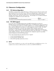
... IDE connectors with independent I /O space, and other system resources. You can automatically configure PCI devices. Intel Desktop Board D865GRH Technical Product Specification 3.3 Resource Configuration 3.3.1 PCI Autoconfiguration The BIOS can override the auto-configuration options by specifying manual configuration in the BIOS Setup program. When a user turns on the same IDE cable as a slave...
... IDE connectors with independent I /O space, and other system resources. You can automatically configure PCI devices. Intel Desktop Board D865GRH Technical Product Specification 3.3 Resource Configuration 3.3.1 PCI Autoconfiguration The BIOS can override the auto-configuration options by specifying manual configuration in the BIOS Setup program. When a user turns on the same IDE cable as a slave...
D865GRH_TechProdSpec.
Page 100
... the system. Both utilities support the following utilities, which are available on the Web. • Intel® Flash Memory Update Utility, which requires creation of a boot diskette and manual rebooting of the BIOS. • Updating replaceable BIOS modules, such as the video BIOS module....MB diskette, or a CD-ROM, or from a legacy diskette drive or an LS-120 diskette drive) or a CD-ROM. Intel Desktop Board D865GRH Technical Product Specification To install an operating system that supports USB, verify that the updated BIOS matches the target system to prevent accidentally ...
... the system. Both utilities support the following utilities, which are available on the Web. • Intel® Flash Memory Update Utility, which requires creation of a boot diskette and manual rebooting of the BIOS. • Updating replaceable BIOS modules, such as the video BIOS module....MB diskette, or a CD-ROM, or from a legacy diskette drive or an LS-120 diskette drive) or a CD-ROM. Intel Desktop Board D865GRH Technical Product Specification To install an operating system that supports USB, verify that the updated BIOS matches the target system to prevent accidentally ...
D865GRH_TechProdSpec.
Page 110
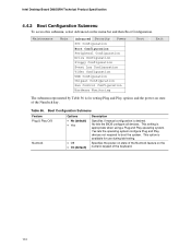
... is available for setting Plug and Play options and the power-on state of the Numlock key. No lets the BIOS configure all devices. Intel Desktop Board D865GRH Technical Product Specification 4.4.2 Boot Configuration Submenu To access this submenu, select Advanced on the numeric keypad of the keyboard. 110 This setting is ...to boot the system. Boot Configuration Submenu Feature Plug & Play O/S Numlock Options • No (default) • Yes • Off • On (default) Description Specifies if manual configuration is appropriate when using a Plug and Play operating system.
... is available for setting Plug and Play options and the power-on state of the Numlock key. No lets the BIOS configure all devices. Intel Desktop Board D865GRH Technical Product Specification 4.4.2 Boot Configuration Submenu To access this submenu, select Advanced on the numeric keypad of the keyboard. 110 This setting is ...to boot the system. Boot Configuration Submenu Feature Plug & Play O/S Numlock Options • No (default) • Yes • Off • On (default) Description Specifies if manual configuration is appropriate when using a Plug and Play operating system.
D865GRH_TechProdSpec.
Page 122
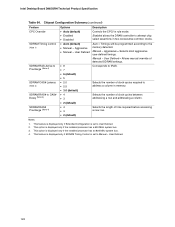
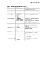
... Selects the number of clock cycles between addressing a row and addressing a column. Enabled allows the DRAM controller to tRAS. Aggressive • Manual - Corresponds to attempt chip select assertions in memory. User Defined • 8 • 7 • 6 (default) • 5...3 • 2 (default) Description Controls the CPC/1n rule mode. User Defined. 122 Intel Desktop Board D865GRH Technical Product Specification Table 64. Auto = Timings will be programmed according to Manual - This feature is displayed only if Extended Configuration is set to User Defined. 2.
... Selects the number of clock cycles between addressing a row and addressing a column. Enabled allows the DRAM controller to tRAS. Aggressive • Manual - Corresponds to attempt chip select assertions in memory. User Defined • 8 • 7 • 6 (default) • 5...3 • 2 (default) Description Controls the CPC/1n rule mode. User Defined. 122 Intel Desktop Board D865GRH Technical Product Specification Table 64. Auto = Timings will be programmed according to Manual - This feature is displayed only if Extended Configuration is set to User Defined. 2.

D865GRH_ProductGuide01_English.
Page 3
...to important information. A Error Messages and Indicators: BIOS error messages and beep codes. Information Layout The chapters in this Product Guide are used in this manual: WARNING Warnings indicate conditions that, if not observed, can cause personal injury. CAUTION Cautions warn the user about board layout, component installation, BIOS Setup ...up the module. 6 Desktop Board Resources: Memory map, DMA channels, and interrupts. B Regulatory Compliance: Regulatory compliance information. Intended Audience The Product Guide is intended for Intel® Desktop Board D865GRH. iii
...to important information. A Error Messages and Indicators: BIOS error messages and beep codes. Information Layout The chapters in this Product Guide are used in this manual: WARNING Warnings indicate conditions that, if not observed, can cause personal injury. CAUTION Cautions warn the user about board layout, component installation, BIOS Setup ...up the module. 6 Desktop Board Resources: Memory map, DMA channels, and interrupts. B Regulatory Compliance: Regulatory compliance information. Intended Audience The Product Guide is intended for Intel® Desktop Board D865GRH. iii
D865GRH_ProductGuide01_English.
Page 15
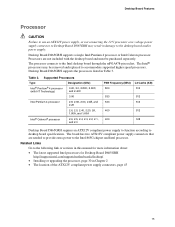
... may result in damage to the following link or sections in this manual for more information about: • The latest supported Intel processors for Desktop Board D865GRH http://support.intel.com/support/motherboards/desktop/ • Installing or upgrading the processor, page...to accommodate supported higher speed processors. The processor connects to the Intel 865G chipset and Intel processor. Table 3. Desktop Board D865GRH supports a single Intel Pentium 4 processor or Intel Celeron processor. Desktop Board D865GRH supports the processors listed in Chapter 2 • The location ...
... may result in damage to the following link or sections in this manual for more information about: • The latest supported Intel processors for Desktop Board D865GRH http://support.intel.com/support/motherboards/desktop/ • Installing or upgrading the processor, page...to accommodate supported higher speed processors. The processor connects to the Intel 865G chipset and Intel processor. Table 3. Desktop Board D865GRH supports a single Intel Pentium 4 processor or Intel Celeron processor. Desktop Board D865GRH supports the processors listed in Chapter 2 • The location ...

D865GRH_ProductGuide01_English.
Page 16
The desktop board supports system memory as defined below: • Dual channel and up . Intel Desktop Boards D865GRH Product Guide Main Memory NOTE To be fully compliant with all applicable Intel® SDRAM memory specification addendums, the board should be populated with gold-plated contacts. &#...8226; SDRAM specifications, http://www.intel.com/technology/memory/pcsdram/spec/ • Installing memory, page 32 in this effect on the screen at power up to the operating system and applications. The BIOS will see a notification to this manual for normal operation. Related Links...
The desktop board supports system memory as defined below: • Dual channel and up . Intel Desktop Boards D865GRH Product Guide Main Memory NOTE To be fully compliant with all applicable Intel® SDRAM memory specification addendums, the board should be populated with gold-plated contacts. &#...8226; SDRAM specifications, http://www.intel.com/technology/memory/pcsdram/spec/ • Installing memory, page 32 in this effect on the screen at power up to the operating system and applications. The BIOS will see a notification to this manual for normal operation. Related Links...
D865GRH_ProductGuide01_English.
Page 18
... is not established. LAN link is established. The computer is selected. The LAN subsystem provides the following link or sections in this manual for RJ-45 connector with status indicator LEDs • Programmable transit threshold • Configurable EEPROM that contains the MAC address LAN Subsystem...Sensing, page 41 in Chapter 2 LAN Subsystem (Optional) The optional LAN provides a Fast PCI LAN subsystem. Intel Desktop Boards D865GRH Product Guide Related Links Go to the D865GRH link on the LAN. 18 RJ-45 10/100/1000 Gigabit Ethernet LAN Connector LEDs LED Color Bi-color ...
... is not established. LAN link is established. The computer is selected. The LAN subsystem provides the following link or sections in this manual for RJ-45 connector with status indicator LEDs • Programmable transit threshold • Configurable EEPROM that contains the MAC address LAN Subsystem...Sensing, page 41 in Chapter 2 LAN Subsystem (Optional) The optional LAN provides a Fast PCI LAN subsystem. Intel Desktop Boards D865GRH Product Guide Related Links Go to the D865GRH link on the LAN. 18 RJ-45 10/100/1000 Gigabit Ethernet LAN Connector LEDs LED Color Bi-color ...
D865GRH_ProductGuide01_English.
Page 20
Intel Desktop Boards D865GRH Product Guide Accelerated Graphics Port (AGP) NOTE Desktop Board D865GRH is stored in the Firmware Hub. BIOS The BIOS provides the Power-On Self-Test (POST), the BIOS Setup program, the PCI and IDE auto-...configuration utilities, and the video BIOS. The BIOS can be accessed and who can be updated by specifying manual configuration in the BIOS...
Intel Desktop Boards D865GRH Product Guide Accelerated Graphics Port (AGP) NOTE Desktop Board D865GRH is stored in the Firmware Hub. BIOS The BIOS provides the Power-On Self-Test (POST), the BIOS Setup program, the PCI and IDE auto-...configuration utilities, and the video BIOS. The BIOS can be accessed and who can be updated by specifying manual configuration in the BIOS...

D865GRH_ProductGuide01_English.
Page 29
... described here. Location of the eight mounting screw holes for instructions on installing and removing the desktop board. Figure 4. Refer to your chassis manual for Desktop Board D865GRH. Figure 4 shows the location of Mounting Screw Holes OM16334 29 Disconnect the computer from its power source before you open the computer can result...
... described here. Location of the eight mounting screw holes for instructions on installing and removing the desktop board. Figure 4. Refer to your chassis manual for Desktop Board D865GRH. Figure 4 shows the location of Mounting Screw Holes OM16334 29 Disconnect the computer from its power source before you open the computer can result...
D865GRH_ProductGuide01_English.
Page 30
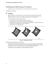
... to the socket (see Figure 2 on how to install the processor to the boxed processor manual or the Intel World Wide Web site at: http://support.intel.com/support/processors/pentium4/intnotes478.htm 30 Failure to its original position. Installing a Processor OM15028 ... Heat Sink Desktop Board D865GRH has an integrated processor fan heat sink retention mechanism (RM). mPGA478B mPGA478B mPGA478B A Figure 5. the standby power LED should not be lit (see Figure 5). 4. To install a processor, follow these instructions: 1. Intel Desktop Boards D865GRH Product Guide Installing and ...
... to the socket (see Figure 2 on how to install the processor to the boxed processor manual or the Intel World Wide Web site at: http://support.intel.com/support/processors/pentium4/intnotes478.htm 30 Failure to its original position. Installing a Processor OM15028 ... Heat Sink Desktop Board D865GRH has an integrated processor fan heat sink retention mechanism (RM). mPGA478B mPGA478B mPGA478B A Figure 5. the standby power LED should not be lit (see Figure 5). 4. To install a processor, follow these instructions: 1. Intel Desktop Boards D865GRH Product Guide Installing and ...
D865GRH_ProductGuide01_English.
Page 31
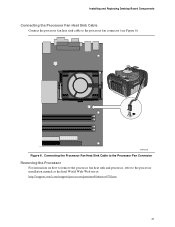
Connecting the Processor Fan Heat Sink Cable to the Processor Fan Connector Removing the Processor For instruction on how to remove the processor fan heat sink and processor, refer to the processor fan connector (see Figure 6). OM15229 Figure 6. Installing and Replacing Desktop Board Components Connecting the Processor Fan Heat Sink Cable Connect the processor fan heat sink cable to the processor installation manual or the Intel World Wide Web site at: http://support.intel.com/support/processors/pentium4/intnotes478.htm 31
Connecting the Processor Fan Heat Sink Cable to the Processor Fan Connector Removing the Processor For instruction on how to remove the processor fan heat sink and processor, refer to the processor fan connector (see Figure 6). OM15229 Figure 6. Installing and Replacing Desktop Board Components Connecting the Processor Fan Heat Sink Cable Connect the processor fan heat sink cable to the processor installation manual or the Intel World Wide Web site at: http://support.intel.com/support/processors/pentium4/intnotes478.htm 31
D865GRH_ProductGuide01_English.
Page 62
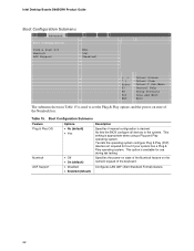
Specifies the power-on state of the Numlock feature on state of the keyboard. Intel Desktop Boards D865GRH Product Guide Boot Configuration Submenu Main Advanced Security Power Boot Exit Boot Configuration Plug & Play O/S Numlock ASF Support [No] [On] [Enabled] m o n p Enter F1 P9 F10 .... • Enabled (default) 62 Boot Configuration Submenu Feature Plug & Play O/S Options • No (default) • Yes Numlock • Off • On (default) Description Specifies if manual configuration is available for boot if your system has a Plug & Play operating system.
Specifies the power-on state of the Numlock feature on state of the keyboard. Intel Desktop Boards D865GRH Product Guide Boot Configuration Submenu Main Advanced Security Power Boot Exit Boot Configuration Plug & Play O/S Numlock ASF Support [No] [On] [Enabled] m o n p Enter F1 P9 F10 .... • Enabled (default) 62 Boot Configuration Submenu Feature Plug & Play O/S Options • No (default) • Yes Numlock • Off • On (default) Description Specifies if manual configuration is available for boot if your system has a Plug & Play operating system.
D865GRH_ProductGuide01_English.
Page 73
... 333-320 MHz • Auto (default) • 266 MHz • 333 MHz • 400 MHz • Auto (default) • Manual - Auto allows timings to be programmed according to tRAS, min. User Defined allows manual override of detected memory frequency value. To Pre. • 8 (default) • 7 • 6 • 5 SDRAM CAS# Latency •... tRCD. Selects length of clock cycles between addressing a row and addressing a column. Using the BIOS Setup Program Table 23. Aggressive • Manual - Manual - Controls Command Per Clock/1n rule mode. Corresponds to pre-change.
... 333-320 MHz • Auto (default) • 266 MHz • 333 MHz • 400 MHz • Auto (default) • Manual - Auto allows timings to be programmed according to tRAS, min. User Defined allows manual override of detected memory frequency value. To Pre. • 8 (default) • 7 • 6 • 5 SDRAM CAS# Latency •... tRCD. Selects length of clock cycles between addressing a row and addressing a column. Using the BIOS Setup Program Table 23. Aggressive • Manual - Manual - Controls Command Per Clock/1n rule mode. Corresponds to pre-change.


