

Product Guide
Page 3
Contents 1 Desktop Board Features Board Components ...9 Processor ...11 Main Memory ...12 Intel® 850 Chipset ...12 Intel® 82850 Memory Controller Hub (MCH 12 Intel® 82801BA I/O Controller Hub (ICH2 13 Firmware Hub (FWH 13 Input/Output (I/O) Controller 13... Features 18 Instantly Available Technology 18 Resume on Ring...20 2 Installing and Replacing Desktop Board Components Before You Begin ...21 Installing the I/O Shield...22 Installing and Removing the Desktop Board 23 Installing and Removing a Processor 25 Installing the Processor Fan Heatsink Retention Mechanism ...
Contents 1 Desktop Board Features Board Components ...9 Processor ...11 Main Memory ...12 Intel® 850 Chipset ...12 Intel® 82850 Memory Controller Hub (MCH 12 Intel® 82801BA I/O Controller Hub (ICH2 13 Firmware Hub (FWH 13 Input/Output (I/O) Controller 13... Features 18 Instantly Available Technology 18 Resume on Ring...20 2 Installing and Replacing Desktop Board Components Before You Begin ...21 Installing the I/O Shield...22 Installing and Removing the Desktop Board 23 Installing and Removing a Processor 25 Installing the Processor Fan Heatsink Retention Mechanism ...

Product Guide
Page 5
...the IDE Cable 36 19. Audio Connectors ...67 23. Contents Desktop Board Resources 73 Memory Map ...73 DMA Channels ...73 I /O Shield 22 5. D850MV Board Components 10 3. Connecting the Processor Fan Cable to the Board 26 9. Removing the AGP Card 34 17. Removing the ... for Intended Applications 85 Figures 1. D850MD Board Power and Hardware Control Connectors 68 24. Back Panel Connectors 66 22. D850MD Board Components 9 2. D850MD Board Add-in Card and Peripheral Interface Connectors 70 v Location of Standby Power Indicator 19 4. D850MV Board Mounting Screw Holes 24 7. AGP...
...the IDE Cable 36 19. Audio Connectors ...67 23. Contents Desktop Board Resources 73 Memory Map ...73 DMA Channels ...73 I /O Shield 22 5. D850MV Board Components 10 3. Connecting the Processor Fan Cable to the Board 26 9. Removing the AGP Card 34 17. Removing the ... for Intended Applications 85 Figures 1. D850MD Board Power and Hardware Control Connectors 68 24. Back Panel Connectors 66 22. D850MD Board Components 9 2. D850MD Board Add-in Card and Peripheral Interface Connectors 70 v Location of Standby Power Indicator 19 4. D850MV Board Mounting Screw Holes 24 7. AGP...

Product Guide
Page 9
Desktop Board Features Board Components Figure 1 shows the location of the major components on the D850MD board. A B CD E F G H I BB J AA K L Z Y X M W V TR US P Q O N OM11828 A ADI AD1885 audio codec P Primary IDE...Intel 82850 Memory Controller Hub (MCH) Y SCSI hard drive activity LED connector K Processor socket Z Intel 82801BA I/O Controller Hub (ICH2) L RIMM sockets AA PCI bus add-in card connectors M RIMM fan connector (fan 1) BB Communication and Networking Riser (CNR) N Power connector (optional) O Floppy drive connector Figure 1. D850MD Board Components...
Desktop Board Features Board Components Figure 1 shows the location of the major components on the D850MD board. A B CD E F G H I BB J AA K L Z Y X M W V TR US P Q O N OM11828 A ADI AD1885 audio codec P Primary IDE...Intel 82850 Memory Controller Hub (MCH) Y SCSI hard drive activity LED connector K Processor socket Z Intel 82801BA I/O Controller Hub (ICH2) L RIMM sockets AA PCI bus add-in card connectors M RIMM fan connector (fan 1) BB Communication and Networking Riser (CNR) N Power connector (optional) O Floppy drive connector Figure 1. D850MD Board Components...

Product Guide
Page 10
Intel Desktop Boards D850MD and D850MV Product Guide Figure 2 shows the location of the major components on the D850MV board. D850MV Board Components 10 A B CD E F G CC H I BB J AA K L Z Y X M W V TR US P Q O N OM12073 A ADI AD1885 audio codec P Primary IDE connector ... W Speaker I Processor fan connector (CPU fan) (tachometer input) X BIOS configuration jumper J Intel 82850 Memory Controller Hub (MCH) Y SCSI hard drive activity LED connector K Processor socket Z Intel 82801BA I/O Controller Hub (ICH2) L RIMM sockets AA PCI bus add-in card connectors M RIMM...
Intel Desktop Boards D850MD and D850MV Product Guide Figure 2 shows the location of the major components on the D850MV board. D850MV Board Components 10 A B CD E F G CC H I BB J AA K L Z Y X M W V TR US P Q O N OM12073 A ADI AD1885 audio codec P Primary IDE connector ... W Speaker I Processor fan connector (CPU fan) (tachometer input) X BIOS configuration jumper J Intel 82850 Memory Controller Hub (MCH) Y SCSI hard drive activity LED connector K Processor socket Z Intel 82801BA I/O Controller Hub (ICH2) L RIMM sockets AA PCI bus add-in card connectors M RIMM...
Product Guide
Page 19
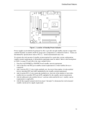
... (ACPI S3 sleep state) configuration as outlined in Table 4 on page 20 and follow the steps outlined below: 1. Note the total D850MD or D850MV board standby current requirement. 2. Add, from the PCI 2.2 slots (wake-enabled) row, the total of the number of Standby Power Indicator... devices' and non-wake-enabled devices' standby current requirements as PCI 2.2. Desktop Board Features CR7F1 OM11834 Figure 3. Add, from the PCI 2.2 slots (nonwake-enabled) row, the total of the number of all installed components must be added. Location of wake-enabled devices installed (PCI and AGP)...
... (ACPI S3 sleep state) configuration as outlined in Table 4 on page 20 and follow the steps outlined below: 1. Note the total D850MD or D850MV board standby current requirement. 2. Add, from the PCI 2.2 slots (wake-enabled) row, the total of the number of Standby Power Indicator... devices' and non-wake-enabled devices' standby current requirements as PCI 2.2. Desktop Board Features CR7F1 OM11834 Figure 3. Add, from the PCI 2.2 slots (nonwake-enabled) row, the total of the number of all installed components must be added. Location of wake-enabled devices installed (PCI and AGP)...
Product Guide
Page 20
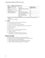
... enabled) CNR** (non-wake enabled) USB ports** Standby Current Requirements (mA) 770* 345 375 100 875 40 700 * Refer to a combined total of Resume on components (Add to integrated board components shown above) Description Total for correct operation 20 Intel Desktop Boards D850MD and D850MV Product Guide Table 4. Resume on Ring The operation of 700 mA.
... enabled) CNR** (non-wake enabled) USB ports** Standby Current Requirements (mA) 770* 345 375 100 875 40 700 * Refer to a combined total of Resume on components (Add to integrated board components shown above) Description Total for correct operation 20 Intel Desktop Boards D850MD and D850MV Product Guide Table 4. Resume on Ring The operation of 700 mA.

Product Guide
Page 21
.... 21 Failure to disconnect power, telecommunications links, networks, or modems before performing any procedures can damage components. 2 Installing and Replacing Desktop Board Components This chapter tells you how to: • Install the I/O shield • Install and remove the desktop board • Install and remove a processor • Install and remove memory • Install and remove an AGP...
.... 21 Failure to disconnect power, telecommunications links, networks, or modems before performing any procedures can damage components. 2 Installing and Replacing Desktop Board Components This chapter tells you how to: • Install the I/O shield • Install and remove the desktop board • Install and remove a processor • Install and remove memory • Install and remove an AGP...
Product Guide
Page 22
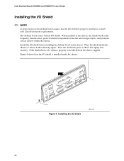
.... Install the I/O shield before installing the desktop board in the following figure. Intel Desktop Boards D850MD and D850MV Product Guide Installing the I/O Shield ✏ NOTE Systems based on this desktop board require that it fits tightly and securely. When installed in the chassis, the shield blocks radio frequency transmissions, protects internal components from the chassis supplier. If the shield...
.... Install the I/O shield before installing the desktop board in the following figure. Intel Desktop Boards D850MD and D850MV Product Guide Installing the I/O Shield ✏ NOTE Systems based on this desktop board require that it fits tightly and securely. When installed in the chassis, the shield blocks radio frequency transmissions, protects internal components from the chassis supplier. If the shield...

Product Guide
Page 23
... installation instructions and precautions. Figure 5 shows the location of each board. OM11831 Figure 5. Refer to Appendix B on installing and removing the board. Installing and Replacing Desktop Board Components Installing and Removing the Desktop Board Refer to your chassis manual for instructions on page 81 for the D850MD board. Disconnect the computer from its power source before you open the...
... installation instructions and precautions. Figure 5 shows the location of each board. OM11831 Figure 5. Refer to Appendix B on installing and removing the board. Installing and Replacing Desktop Board Components Installing and Removing the Desktop Board Refer to your chassis manual for instructions on page 81 for the D850MD board. Disconnect the computer from its power source before you open the...

Product Guide
Page 25
... Holes 25 Observe the precautions in "Before You Begin" on how to install the processor fan heatsink, refer to the desktop board are given below. To install the processor fan heatsink RM base, follow these instructions: 1. Locate the processor fan heatsink... or the Intel World Wide Web site at: http://support.intel.com/support/motherboards/desktop Installing the Processor Fan Heatsink Retention Mechanism Base ✏ NOTE The following assembly operation should be performed after the desktop board is secured in the chassis. Installing and Replacing Desktop Board Components Installing and...
... Holes 25 Observe the precautions in "Before You Begin" on how to install the processor fan heatsink, refer to the desktop board are given below. To install the processor fan heatsink RM base, follow these instructions: 1. Locate the processor fan heatsink... or the Intel World Wide Web site at: http://support.intel.com/support/motherboards/desktop Installing the Processor Fan Heatsink Retention Mechanism Base ✏ NOTE The following assembly operation should be performed after the desktop board is secured in the chassis. Installing and Replacing Desktop Board Components Installing and...

Product Guide
Page 27
...Begin" on how to install the processor fan heatsink, refer to the boxed processor manual or the Intel World Wide Web site at: http://support.intel.com/support/motherboards/desktop 27 Locate the processor socket and raise the socket lever completely. 3. Installing a Processor OM12078 Installing...9. Failure to its original position. the standby power LED should not be lit (see Figure 9). 4. Installing and Replacing Desktop Board Components Installing a Processor CAUTION Before installing or removing the processor, make sure that the corner with the triangle marking (A) is aligned...
...Begin" on how to install the processor fan heatsink, refer to the boxed processor manual or the Intel World Wide Web site at: http://support.intel.com/support/motherboards/desktop 27 Locate the processor socket and raise the socket lever completely. 3. Installing a Processor OM12078 Installing...9. Failure to its original position. the standby power LED should not be lit (see Figure 9). 4. Installing and Replacing Desktop Board Components Installing a Processor CAUTION Before installing or removing the processor, make sure that the corner with the triangle marking (A) is aligned...

Product Guide
Page 29
...sided). • If the desired memory configuration has been achieved in bank 0, install CRIMMs in the sockets in a RIMM connector can damage the D850MD and D850MV boards. RDRAM and CRIMM Installation Bank 0 Bank 1 29 The pair of a RIMM module or a CRIMM module in bank 1 (see Figure 3...module requirements are listed in the Main Memory section on page 19 for bank 0, as bank 0 and bank 1. Installing and Replacing Desktop Board Components Installing and Removing Memory CAUTIONS Before installing or removing RIMM modules, make sure that ac power has been removed by unplugging the power...
...sided). • If the desired memory configuration has been achieved in bank 0, install CRIMMs in the sockets in a RIMM connector can damage the D850MD and D850MV boards. RDRAM and CRIMM Installation Bank 0 Bank 1 29 The pair of a RIMM module or a CRIMM module in bank 1 (see Figure 3...module requirements are listed in the Main Memory section on page 19 for bank 0, as bank 0 and bank 1. Installing and Replacing Desktop Board Components Installing and Removing Memory CAUTIONS Before installing or removing RIMM modules, make sure that ac power has been removed by unplugging the power...

Product Guide
Page 31
... the module until the retaining clips snap into the socket. 6. Reinstall and reconnect any parts you removed or disconnected to the computer. Installing and Replacing Desktop Board Components To install the memory modules, follow these steps (see Figure 13): 1. Position the module above the socket. Align the two small notches in "Before You...
... the module until the retaining clips snap into the socket. 6. Reinstall and reconnect any parts you removed or disconnected to the computer. Installing and Replacing Desktop Board Components To install the memory modules, follow these steps (see Figure 13): 1. Position the module above the socket. Align the two small notches in "Before You...

Product Guide
Page 33
... underneath the AGP connector. do To avoid damaging the board, not apply unnecessary pressure. Note that the board's silkscreen (C) indicates the correct final position of the AGP connector. OM10111 3. Installing and Replacing Desktop Board Components The AGP card RM (see Figure 15) encloses the board's AGP connector and stabilizes the AGP card. Follow the... a flat, supportive surface. Position the AGP card RM over the end of the lever (D) on the AGP card RM. OM10181 33 Place the board (component side up) on the board as shown below. A D E C B OM11842 Figure 15.
... underneath the AGP connector. do To avoid damaging the board, not apply unnecessary pressure. Note that the board's silkscreen (C) indicates the correct final position of the AGP connector. OM10111 3. Installing and Replacing Desktop Board Components The AGP card RM (see Figure 15) encloses the board's AGP connector and stabilizes the AGP card. Follow the... a flat, supportive surface. Position the AGP card RM over the end of the lever (D) on the AGP card RM. OM10181 33 Place the board (component side up) on the board as shown below. A D E C B OM11842 Figure 15.

Product Guide
Page 35
Spread the sides of the RM (C) and lift the AGP card RM off of the AGP card RM (see Figure 17). 2. Removing the AGP Card Retention Mechanism 35 B c A c OM10593 Figure 17. Using diagonal cutters (A), cut the loop (B) joining the two sides of the AGP connector. ✏ NOTE Once removed using this method, the AGP card RM cannot be reused. Installing and Replacing Desktop Board Components Removing the AGP Card Retention Mechanism Follow these instructions to remove the AGP card RM: 1.
Spread the sides of the RM (C) and lift the AGP card RM off of the AGP card RM (see Figure 17). 2. Removing the AGP Card Retention Mechanism 35 B c A c OM10593 Figure 17. Using diagonal cutters (A), cut the loop (B) joining the two sides of the AGP connector. ✏ NOTE Once removed using this method, the AGP card RM cannot be reused. Installing and Replacing Desktop Board Components Removing the AGP Card Retention Mechanism Follow these instructions to remove the AGP card RM: 1.

Product Guide
Page 37
The location of the BIOS Configuration Jumper The three-pin BIOS jumper enables the board configuration to be done in BIOS Setup. The BIOS attempts to clear passwords. Installing and Replacing Desktop Board Components Setting the BIOS Configuration Jumper CAUTION Always turn off the power and unplug the power cord from the computer before changing... jumper settings for booting. After the POST runs, the BIOS displays the maintenance menu. Use this menu to recover the BIOS configuration. Location of the board's BIOS configuration jumper (J9H2) is required. 37
The location of the BIOS Configuration Jumper The three-pin BIOS jumper enables the board configuration to be done in BIOS Setup. The BIOS attempts to clear passwords. Installing and Replacing Desktop Board Components Setting the BIOS Configuration Jumper CAUTION Always turn off the power and unplug the power cord from the computer before changing... jumper settings for booting. After the POST runs, the BIOS displays the maintenance menu. Use this menu to recover the BIOS configuration. Location of the board's BIOS configuration jumper (J9H2) is required. 37

Product Guide
Page 39
...övårdsbestämmelserna. (Swedish) VARO Räjähdysvaara, jos pariston tyyppi on page 41 shows the location of the battery. Installing and Replacing Desktop Board Components Replacing the Battery A coin-cell battery (CR2032) powers the real-time clock and CMOS memory. When the computer is not plugged into a wall socket, the...
...övårdsbestämmelserna. (Swedish) VARO Räjähdysvaara, jos pariston tyyppi on page 41 shows the location of the battery. Installing and Replacing Desktop Board Components Replacing the Battery A coin-cell battery (CR2032) powers the real-time clock and CMOS memory. When the computer is not plugged into a wall socket, the...

Product Guide
Page 41
... pry the battery free from the ac power source (wall outlet or power adapter). 3. Note the orientation of the "+" and "-" on the board (see Figure 20). 5. OM11833 Figure 20. Removing the Battery . 41 Installing and Replacing Desktop Board Components To replace the battery, follow these steps: 1. Disconnect the computer's power cord from its connector.
... pry the battery free from the ac power source (wall outlet or power adapter). 3. Note the orientation of the "+" and "-" on the board (see Figure 20). 5. OM11833 Figure 20. Removing the Battery . 41 Installing and Replacing Desktop Board Components To replace the battery, follow these steps: 1. Disconnect the computer's power cord from its connector.
Product Guide
Page 47
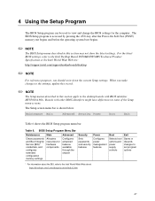
...show the latest settings. Table 6. For the latest BIOS settings, refer to the Intel Desktop Board D850MD/D850MV Technical Product Specification or the Intel World Wide Web site: http://support.intel.com/support/motherboards/desktop ✏ NOTE For reference purposes, you make changes to the settings, update this...Using the Setup Program The BIOS Setup program can be used to view and change the BIOS settings for hardware components Configures advanced features available through the chipset Sets passwords and security features Configures power management features Selects boot options and...
...show the latest settings. Table 6. For the latest BIOS settings, refer to the Intel Desktop Board D850MD/D850MV Technical Product Specification or the Intel World Wide Web site: http://support.intel.com/support/motherboards/desktop ✏ NOTE For reference purposes, you make changes to the settings, update this...Using the Setup Program The BIOS Setup program can be used to view and change the BIOS settings for hardware components Configures advanced features available through the chipset Sets passwords and security features Configures power management features Selects boot options and...

Product Guide
Page 82
... number (solder side): A49682-002 (for D850MD board) A56437-001 (for D850MV board) Also includes SKU number starting with AA followed by a small US. Intel Desktop Boards D850MD and D850MV Product Guide Product Certification Markings The desktop boards have the following product certification markings: • UL joint US/Canada Recognized Component mark: consists of small c followed by a stylized...
... number (solder side): A49682-002 (for D850MD board) A56437-001 (for D850MV board) Also includes SKU number starting with AA followed by a small US. Intel Desktop Boards D850MD and D850MV Product Guide Product Certification Markings The desktop boards have the following product certification markings: • UL joint US/Canada Recognized Component mark: consists of small c followed by a stylized...


