
Product Specification
Page 8
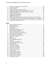
... 18. Rear Chassis Fan Connector 62 30. Processor Fan Connector 62 31. Main Power Connector 63 viii Audio Connectors ...59 13. Location of the Standby Power Indicator LED 44 11. Specifications ...19 5. Interrupts ...51 17. LAN Connector (Optional 57 23. Auxiliary Line In Connector 60 27. Power and Hardware Control Connectors 61 14. Summary of Pressing the Power Switch 39 9. Feature Summary...12 3. Effects of Board Differences 11 2. Intel Desktop Board D845BG/D845PT Technical Product Specification 10. Back Panel Connectors 55 12...
... 18. Rear Chassis Fan Connector 62 30. Processor Fan Connector 62 31. Main Power Connector 63 viii Audio Connectors ...59 13. Location of the Standby Power Indicator LED 44 11. Specifications ...19 5. Interrupts ...51 17. LAN Connector (Optional 57 23. Auxiliary Line In Connector 60 27. Power and Hardware Control Connectors 61 14. Summary of Pressing the Power Switch 39 9. Feature Summary...12 3. Effects of Board Differences 11 2. Intel Desktop Board D845BG/D845PT Technical Product Specification 10. Back Panel Connectors 55 12...

Product Specification
Page 29
... IDE bus allows host and target throttling. floppy disk drive) • ARMD-HDD (ATAPI removable media device - The BIOS supports Logical Block Addressing (LBA) and Extended Cylinder Head Sector (ECHS) translation modes. The D845BG and D845PT boards support Laser Servo (LS-120) diskette technology through the IDE interfaces. An LS-120 drive can be independently enabled. For proper operation, this connector should be wired to the LED output of the IDE connectors BIOS Setup program's Boot menu...
... IDE bus allows host and target throttling. floppy disk drive) • ARMD-HDD (ATAPI removable media device - The BIOS supports Logical Block Addressing (LBA) and Extended Cylinder Head Sector (ECHS) translation modes. The D845BG and D845PT boards support Laser Servo (LS-120) diskette technology through the IDE interfaces. An LS-120 drive can be independently enabled. For proper operation, this connector should be wired to the LED output of the IDE connectors BIOS Setup program's Boot menu...

Product Specification
Page 36
... LAN device) OM12277 Figure 9. or six-channel audio using a CNR audio upgrade card in multiple configurations from several different vendors supporting analog or S/P-DIF digital connections. For information about the CNR, refer to Section 1.3, page 18 1.12 CNR (Optional) The CNR connector provides an interface that supports the audio, modem, USB, and LAN interfaces of vendors supplying CNR audio upgrade cards compatible with the D845BG/D845PT boards' onboard audio subsystem, as well as an installation guide for these cards...
... LAN device) OM12277 Figure 9. or six-channel audio using a CNR audio upgrade card in multiple configurations from several different vendors supporting analog or S/P-DIF digital connections. For information about the CNR, refer to Section 1.3, page 18 1.12 CNR (Optional) The CNR connector provides an interface that supports the audio, modem, USB, and LAN interfaces of vendors supplying CNR audio upgrade cards compatible with the D845BG/D845PT boards' onboard audio subsystem, as well as an installation guide for these cards...
Product Specification
Page 54
... ATAPI CD-ROM) Fans Power Add-in boards (PCI and AGP) CNR (optional) IDE Diskette drive SCSI LED • External I/O connectors (see page 71) Front panel audio Front panel USB Serial port B Auxiliary front panel power/sleep/message-waiting LED Front panel (power/sleep/message-waiting LED, power switch, hard drive activity LED, reset switch, and auxiliary front panel power LED) ✏ NOTE When installing the board in the load presented by the external devices could...
... ATAPI CD-ROM) Fans Power Add-in boards (PCI and AGP) CNR (optional) IDE Diskette drive SCSI LED • External I/O connectors (see page 71) Front panel audio Front panel USB Serial port B Auxiliary front panel power/sleep/message-waiting LED Front panel (power/sleep/message-waiting LED, power switch, hard drive activity LED, reset switch, and auxiliary front panel power LED) ✏ NOTE When installing the board in the load presented by the external devices could...

Product Specification
Page 92
...-ROM drives, tape drives, and Ultra DMA drives (see Section 1.5. 3.3.2 PCI IDE Support If you select Auto in the BIOS Setup program. To use by the BIOS, see Section 1.5 for the supported version of the drive. Autoconfiguration information is grouped into eight 64-KB blocks that of PCI and Plug and Play supported by the add-in ESCD format. Internally, the device is stored in card. Intel Desktop Board D845BG/D845PT Technical Product Specification 3.2 BIOS Flash Memory Organization The Intel...
...-ROM drives, tape drives, and Ultra DMA drives (see Section 1.5. 3.3.2 PCI IDE Support If you select Auto in the BIOS Setup program. To use by the BIOS, see Section 1.5 for the supported version of the drive. Autoconfiguration information is grouped into eight 64-KB blocks that of PCI and Plug and Play supported by the add-in ESCD format. Internally, the device is stored in card. Intel Desktop Board D845BG/D845PT Technical Product Specification 3.2 BIOS Flash Memory Organization The Intel...

Product Specification
Page 99
... BIOS settings for the computer. Table 57. Maintenance Main Advanced Security Power Boot Exit Table 57 lists the BIOS Setup program menu features. Section 2.9 on page 75 tells how to put the board in configuration mode. The menu bar is in configuration mode. 99 however, the maintenance menu is displayed only when the board is shown below. The BIOS Setup program is accessed by pressing the key after the Power-On Self-Test (POST) memory...
... BIOS settings for the computer. Table 57. Maintenance Main Advanced Security Power Boot Exit Table 57 lists the BIOS Setup program menu features. Section 2.9 on page 75 tells how to put the board in configuration mode. The menu bar is in configuration mode. 99 however, the maintenance menu is displayed only when the board is shown below. The BIOS Setup program is accessed by pressing the key after the Power-On Self-Test (POST) memory...

Product Specification
Page 100
... Menu To access this menu in Table 59 is for configuration mode setting information. Displays CPU Information. See Section 2.9 on the menu bar at the top of the screen. Maintenance Menu Feature Options Clear All Passwords • Yes (default) • No Clear BIS Credentials • Yes (default) • No Extended Configuration • Default (default) • User-Defined CPU Information No options CPU Stepping Signature No options CPU Microcode Update Revision No options Description Clears the user and supervisor passwords. Table 58. Intel Desktop Board...
... Menu To access this menu in Table 59 is for configuration mode setting information. Displays CPU Information. See Section 2.9 on the menu bar at the top of the screen. Maintenance Menu Feature Options Clear All Passwords • Yes (default) • No Clear BIS Credentials • Yes (default) • No Extended Configuration • Default (default) • User-Defined CPU Information No options CPU Stepping Signature No options CPU Microcode Update Revision No options Description Clears the user and supervisor passwords. Table 58. Intel Desktop Board...

Product Specification
Page 101
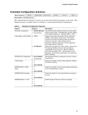
... Main Advanced Security Extended Configuration Power Boot Exit The submenu represented by the processor. Table 60. Cache lookups are not performed. Extended Configuration Submenu Feature Extended Configuration Video Memory Cache Mode Options • Default (default) • User Defined • USWC • UC (default) Description User Defined allows setting memory control and video memory cache mode. Selects UnCacheable (UC) video memory cache mode. Cache lookups are not performed. This setting identifies the video memory range as : "Extended Menu: Used...
... Main Advanced Security Extended Configuration Power Boot Exit The submenu represented by the processor. Table 60. Cache lookups are not performed. Extended Configuration Submenu Feature Extended Configuration Video Memory Cache Mode Options • Default (default) • User Defined • USWC • UC (default) Description User Defined allows setting memory control and video memory cache mode. Selects UnCacheable (UC) video memory cache mode. Cache lookups are not performed. This setting identifies the video memory range as : "Extended Menu: Used...
Product Specification
Page 108
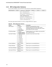
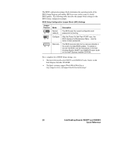
... type of DMA for hard drive BIOS INT13 reads and writes. Intel Desktop Board D845BG/D845PT Technical Product Specification 4.4.4 IDE Configuration Submenu To access this submenu, select Advanced on the menu bar and then IDE Configuration. Maintenance Main Advanced Security Power PCI Configuration Boot Configuration Peripheral Configuration IDE Configuration Diskette Configuration Event Log Configuration Video Configuration Boot Exit The menu represented in Table 66 is used to display sub-menu Description Specifies the integrated IDE controller. Reports type of connected IDE device...
... type of DMA for hard drive BIOS INT13 reads and writes. Intel Desktop Board D845BG/D845PT Technical Product Specification 4.4.4 IDE Configuration Submenu To access this submenu, select Advanced on the menu bar and then IDE Configuration. Maintenance Main Advanced Security Power PCI Configuration Boot Configuration Peripheral Configuration IDE Configuration Diskette Configuration Event Log Configuration Video Configuration Boot Exit The menu represented in Table 66 is used to display sub-menu Description Specifies the integrated IDE controller. Reports type of connected IDE device...
Product Specification
Page 111
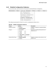
... (default) • Enabled Description Disables or enables the integrated diskette controller. Specifies the capacity and physical size of diskette drive A. Disables or enables write protection for configuring the diskette drive. Table 68. Maintenance Main Advanced Security Power PCI Configuration Boot Configuration Peripheral Configuration IDE Configuration Diskette Configuration Event Log Configuration Video Configuration Boot Exit The submenu represented by Table 68 is used for the diskette drive. 111 BIOS Setup Program 4.4.5 Diskette Configuration Submenu To access this...
... (default) • Enabled Description Disables or enables the integrated diskette controller. Specifies the capacity and physical size of diskette drive A. Disables or enables write protection for configuring the diskette drive. Table 68. Maintenance Main Advanced Security Power PCI Configuration Boot Configuration Peripheral Configuration IDE Configuration Diskette Configuration Event Log Configuration Video Configuration Boot Exit The submenu represented by Table 68 is used for the diskette drive. 111 BIOS Setup Program 4.4.5 Diskette Configuration Submenu To access this...
Product Specification
Page 117
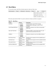
... flash memory for user binary files that are executed at the top of the screen. Specifies the boot sequence from the available types of POST messages. Table 74. Specifies the boot sequence from USB boot devices. Enables the computer to display submenu Description Disabled displays normal POST messages. Maintenance Main Advanced Security Power Boot Exit Boot Device Priority Hard Disk Drives Removable Devices ATAPI CD-ROM Drives The menu represented in Table 74 is used to boot without running certain POST tests. BIOS Setup Program 4.7 Boot Menu...
... flash memory for user binary files that are executed at the top of the screen. Specifies the boot sequence from the available types of POST messages. Table 74. Specifies the boot sequence from USB boot devices. Enables the computer to display submenu Description Disabled displays normal POST messages. Maintenance Main Advanced Security Power Boot Exit Boot Device Priority Hard Disk Drives Removable Devices ATAPI CD-ROM Drives The menu represented in Table 74 is used to boot without running certain POST tests. BIOS Setup Program 4.7 Boot Menu...
Product Specification
Page 123
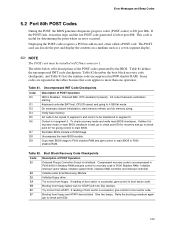
... of the POST codes generated by the BIOS. Keyboard controller BAT test, CPU ID saved, and going to I/O port 80h. Control is in ROM image. Find Main BIOS module in segment 0. Initialize floppy drive. Booting from floppy. Displaying the POST-codes requires a PCI bus add-in F000 shadow RAM. Do necessary chipset initialization, start memory refresh, and do memory sizing. To check recovery mode and verify main BIOS checksum. Copy main BIOS image to F000 shadow RAM and give control to boot from floppy failed, look...
... of the POST codes generated by the BIOS. Keyboard controller BAT test, CPU ID saved, and going to I/O port 80h. Control is in ROM image. Find Main BIOS module in segment 0. Initialize floppy drive. Booting from floppy. Displaying the POST-codes requires a PCI bus add-in F000 shadow RAM. Do necessary chipset initialization, start memory refresh, and do memory sizing. To check recovery mode and verify main BIOS checksum. Copy main BIOS image to F000 shadow RAM and give control to boot from floppy failed, look...

Product Specification
Page 128
...-board System devices 2 ISA devices 3 EISA devices 4 ISA PnP devices 5 PCI devices 5.4 Speaker A 47 Ω inductive speaker is mounted on the D845BG and the D845PT board. The BIOS also issues a beep code (one long tone followed by two short tones) during POST if the video configuration fails (a faulty video card or no card installed) or if an external ROM module does not properly checksum to zero. The speaker provides audible error code (beep code) information during POST, the BIOS displays an error message...
...-board System devices 2 ISA devices 3 EISA devices 4 ISA PnP devices 5 PCI devices 5.4 Speaker A 47 Ω inductive speaker is mounted on the D845BG and the D845PT board. The BIOS also issues a beep code (one long tone followed by two short tones) during POST if the video configuration fails (a faulty video card or no card installed) or if an external ROM module does not properly checksum to zero. The speaker provides audible error code (beep code) information during POST, the BIOS displays an error message...

Intel Desktop Board D845PT/D845BG Product Guide
Page 18
... PCI LAN subsystem providing both the supervisor and user passwords are set, you can boot the computer. Intel Desktop Boards D845PT and D845BG Product Guide IDE Auto Configuration If you install an IDE device (such as a hard drive) in your computer, the IDE auto-configuration utility in the BIOS Setup program. To use ATA-66/100 features, the following restrictions: • The supervisor password gives unrestricted access to Setup. • If both 10Base-T and 100Base-TX connectivity. The password prompt is displayed...
... PCI LAN subsystem providing both the supervisor and user passwords are set, you can boot the computer. Intel Desktop Boards D845PT and D845BG Product Guide IDE Auto Configuration If you install an IDE device (such as a hard drive) in your computer, the IDE auto-configuration utility in the BIOS Setup program. To use ATA-66/100 features, the following restrictions: • The supervisor password gives unrestricted access to Setup. • If both 10Base-T and 100Base-TX connectivity. The password prompt is displayed...
Intel Desktop Board D845PT/D845BG Product Guide
Page 47
...: http://support.intel.com/support/motherboards/desktop ✏ NOTE For reference purposes, you should write down the current Setup settings. Maintenance Main Advanced Security Power Boot Exit Table 6 shows the BIOS Setup program menu bar. Boards with BIOS identifier PT84510A.86A. Table 6. The BIOS Setup program is shown below. BIOS Setup Program Menu Bar Maintenance Clears passwords and Boot Integrity Service (BIS)* credentials, and configures extended configuration memory settings Main Allocates resources for the computer. The Setup screen menu bar is accessed by...
...: http://support.intel.com/support/motherboards/desktop ✏ NOTE For reference purposes, you should write down the current Setup settings. Maintenance Main Advanced Security Power Boot Exit Table 6 shows the BIOS Setup program menu bar. Boards with BIOS identifier PT84510A.86A. Table 6. The BIOS Setup program is shown below. BIOS Setup Program Menu Bar Maintenance Clears passwords and Boot Integrity Service (BIS)* credentials, and configures extended configuration memory settings Main Allocates resources for the computer. The Setup screen menu bar is accessed by...

Intel Desktop Board D845PT/D845BG Product Guide
Page 48
... (default) • No Clear BIS Credentials • Yes (default) • No Extended Configuration No options CPU Stepping Signature No options CPU Microcode Update Revision No options Description Clears the user and administrative passwords. Table 7. Intel Desktop Boards D845PT and D845BG Product Guide Table 7 shows the function keys available for the current menu Save the current values and exits the BIOS Setup program Exits the menu Maintenance Menu Maintenance Main Advanced Security Power Boot Exit The menu shown in configure mode.
... (default) • No Clear BIS Credentials • Yes (default) • No Extended Configuration No options CPU Stepping Signature No options CPU Microcode Update Revision No options Description Clears the user and administrative passwords. Table 7. Intel Desktop Boards D845PT and D845BG Product Guide Table 7 shows the function keys available for the current menu Save the current values and exits the BIOS Setup program Exits the menu Maintenance Menu Maintenance Main Advanced Security Power Boot Exit The menu shown in configure mode.
Intel Desktop Board D845PT/D845BG Product Guide
Page 49
...; 3 • 2 • Auto (default) • 3 • 2 • Auto (default) • 7 • 6 • 5 • Auto (default) Description User Defined allows setting memory control and video memory cache mode. Cache lookups are written to set system control and video memory cache mode. Using the Setup Program Extended Configuration Submenu Maintenance Main Advanced Security Extended Configuration Power Boot Exit This submenu shown in Table 9 is selected under Extended Configuration. If selected here, will also display in the Advanced Menu as: "Extended Menu: Used."
...; 3 • 2 • Auto (default) • 3 • 2 • Auto (default) • 7 • 6 • 5 • Auto (default) Description User Defined allows setting memory control and video memory cache mode. Cache lookups are written to set system control and video memory cache mode. Using the Setup Program Extended Configuration Submenu Maintenance Main Advanced Security Extended Configuration Power Boot Exit This submenu shown in Table 9 is selected under Extended Configuration. If selected here, will also display in the Advanced Menu as: "Extended Menu: Used."
Intel Desktop Board D845PT/D845BG Product Guide
Page 55
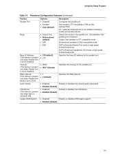
... port. Enables or disables the LAN device. Using the Setup Program Table 14. An * (asterisk) displayed next to ECP) Audio Device LAN Device (This feature is present only when there is Extended Parallel Port mode, a high-speed bi-directional mode. ECP is disabled. Enables or disables the onboard audio subsystem. Enables or disables USB legacy support. 55 Peripheral Configuration Submenu (continued) Feature Parallel Port Mode Base I /O address for the parallel port. EPP is onboard LAN) Legacy USB Support Options • Disabled • Enabled • Auto (default...
... port. Enables or disables the LAN device. Using the Setup Program Table 14. An * (asterisk) displayed next to ECP) Audio Device LAN Device (This feature is present only when there is Extended Parallel Port mode, a high-speed bi-directional mode. ECP is disabled. Enables or disables the onboard audio subsystem. Enables or disables USB legacy support. 55 Peripheral Configuration Submenu (continued) Feature Parallel Port Mode Base I /O address for the parallel port. EPP is onboard LAN) Legacy USB Support Options • Disabled • Enabled • Auto (default...

Intel Desktop Board D845PT/D845BG Product Guide
Page 61
...; No Access Sets BIOS Setup Utility access rights for user level. • View Only • Full (default) • Enabled • Disabled (default) Enabled allows system to enter a password. 4. When Unattended Start is enabled, a USB aware operating system may override user password protection if used to enter a password. 61 Using the Setup Program Security Menu Maintenance Main Advanced Security Power Boot The menu shown in Table 20 is used in the Security menu) are enabled, USB aware operating systems can unlock a PS/2 style keyboard and...
...; No Access Sets BIOS Setup Utility access rights for user level. • View Only • Full (default) • Enabled • Disabled (default) Enabled allows system to enter a password. 4. When Unattended Start is enabled, a USB aware operating system may override user password protection if used to enter a password. 61 Using the Setup Program Security Menu Maintenance Main Advanced Security Power Boot The menu shown in Table 20 is used in the Security menu) are enabled, USB aware operating systems can unlock a PS/2 style keyboard and...
Quick Reference Guide
Page 20
... Intel® Express Installer CD-ROM. Use this menu to clear passwords. 3 1 Recovery The BIOS recovers data from a recovery diskette in the event of BIOS Setup settings, see the instructions in the event of a failed BIOS update. The BIOS configuration jumper block determines the operating mode of the BIOS Setup Program and enables BIOS recovery in the Intel Desktop Boards D845PT and D45BG Product Guide on the Intel Express Installer CD-ROM • The Intel customer support World Wide Web Site at http://support.intel.com/support/motherboards/desktop/ 20 Intel Desktop Boards D845PT...
... Intel® Express Installer CD-ROM. Use this menu to clear passwords. 3 1 Recovery The BIOS recovers data from a recovery diskette in the event of BIOS Setup settings, see the instructions in the event of a failed BIOS update. The BIOS configuration jumper block determines the operating mode of the BIOS Setup Program and enables BIOS recovery in the Intel Desktop Boards D845PT and D45BG Product Guide on the Intel Express Installer CD-ROM • The Intel customer support World Wide Web Site at http://support.intel.com/support/motherboards/desktop/ 20 Intel Desktop Boards D845PT...


