

Product Specification
Page 18
... and Electronic Engineers. Revision 1.0, September 29, 1997, Intel Corporation. Intel Desktop Board D845PEBT2 Technical Product Specification Table 3. http://www.jedec.org/ http://www.jedec.org/ http://developer.intel.com/ technology/memory/ index.htm http://developer.intel.com/ technology/usb/download/ ehci-r10.pdf http://standards.ieee.org/ reading/ieee/std_public/ description/busarch/ 1284.1-1997_desc.html http...
... and Electronic Engineers. Revision 1.0, September 29, 1997, Intel Corporation. Intel Desktop Board D845PEBT2 Technical Product Specification Table 3. http://www.jedec.org/ http://www.jedec.org/ http://developer.intel.com/ technology/memory/ index.htm http://developer.intel.com/ technology/usb/download/ ehci-r10.pdf http://standards.ieee.org/ reading/ieee/std_public/ description/busarch/ 1284.1-1997_desc.html http...

Product Specification
Page 21
Product Description 1.6 System Memory The Desktop Board D845PEBT2 has two DIMM sockets and supports the following memory features: • 2.5 V (only) 184-... with DIMMs that support the Serial Presence Detect (SPD) data structure. This allows the BIOS to read the SPD data and program the chipset to Section 1.4, page 17 21 If non-SPD memory is installed, the... SDRAM memory specifications, the Desktop Board should be impacted or the DIMMs may be populated with the following Intel web sites for the latest lists of up to support DIMMs based on this Desktop Board. Please refer to...
Product Description 1.6 System Memory The Desktop Board D845PEBT2 has two DIMM sockets and supports the following memory features: • 2.5 V (only) 184-... with DIMMs that support the Serial Presence Detect (SPD) data structure. This allows the BIOS to read the SPD data and program the chipset to Section 1.4, page 17 21 If non-SPD memory is installed, the... SDRAM memory specifications, the Desktop Board should be impacted or the DIMMs may be populated with the following Intel web sites for the latest lists of up to support DIMMs based on this Desktop Board. Please refer to...
Product Specification
Page 25
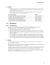
... target throttling and transfer rates of up to reduce reflections, noise, and inductive coupling. The BIOS supports Logical Block Addressing (LBA) and Extended Cylinder Head Sector (ECHS) translation modes. Use...XP drivers and is not currently supported by any other operating system. The Desktop Board D845PEBT2 supports Laser Servo (LS-120) diskette technology through the IDE interfaces. For information about...IDE Interfaces The ICH4's IDE controller has two independent bus-mastering IDE interfaces that can achieve read transfer rates up to 100 MB/sec and write transfer rates up to 88 MB/sec....
... target throttling and transfer rates of up to reduce reflections, noise, and inductive coupling. The BIOS supports Logical Block Addressing (LBA) and Extended Cylinder Head Sector (ECHS) translation modes. Use...XP drivers and is not currently supported by any other operating system. The Desktop Board D845PEBT2 supports Laser Servo (LS-120) diskette technology through the IDE interfaces. For information about...IDE Interfaces The ICH4's IDE controller has two independent bus-mastering IDE interfaces that can achieve read transfer rates up to 100 MB/sec and write transfer rates up to 88 MB/sec....
Product Specification
Page 26
...Real-Time Clock, CMOS SRAM, and Battery A coin-cell battery (CR2032) powers the real-time clock and CMOS memory. Intel Desktop Board D845PEBT2 Technical Product Specification ✏ NOTE The BIOS will be wired to the LED output of the add-in , the standby current from , or written to, both the... Firmware Hub (FWH) The 4 Mbit FWH provides the following: • System BIOS program • Logic that allows an add-in hard drive controller and the IDE controller. The clock is being read from the power supply extends the life of platform information 26 For information about The...
...Real-Time Clock, CMOS SRAM, and Battery A coin-cell battery (CR2032) powers the real-time clock and CMOS memory. Intel Desktop Board D845PEBT2 Technical Product Specification ✏ NOTE The BIOS will be wired to the LED output of the add-in , the standby current from , or written to, both the... Firmware Hub (FWH) The 4 Mbit FWH provides the following: • System BIOS program • Logic that allows an add-in hard drive controller and the IDE controller. The clock is being read from the power supply extends the life of platform information 26 For information about The...
Product Specification
Page 105
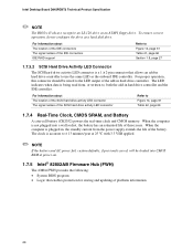
BIOS Setup Program 4.4.4 IDE Configuration Submenu To access this submenu, select Advanced on the menu bar and then IDE Configuration. Reports type of connected IDE device. ... disk drive pre-delay. Secondary enables only the secondary IDE controller. Both enables both IDE controllers. Enables/disables the use of DMA for hard drive BIOS INT13 reads and writes. Primary enables only the primary IDE controller.
BIOS Setup Program 4.4.4 IDE Configuration Submenu To access this submenu, select Advanced on the menu bar and then IDE Configuration. Reports type of connected IDE device. ... disk drive pre-delay. Secondary enables only the secondary IDE controller. Both enables both IDE controllers. Enables/disables the use of DMA for hard drive BIOS INT13 reads and writes. Primary enables only the primary IDE controller.
Product Specification
Page 118
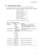
.... Press to four ATAPI CD-ROM drives, the maximum number of the screen. This list will display up to set , the BIOS reads the factory defaults. If this memory is installed. Select the boot device with or . 2. Load Optimal Defaults Loads the optimal default...Table 88 is for exiting the BIOS Setup program, saving changes, and loading and saving defaults. Table 87. Exit Discarding Changes Exits without exiting Setup. Save Custom Defaults Saves the current values as the intended boot device. Intel Desktop Board D845PEBT2 Technical Product Specification 4.7.4 ATAPI CD...
.... Press to four ATAPI CD-ROM drives, the maximum number of the screen. This list will display up to set , the BIOS reads the factory defaults. If this memory is installed. Select the boot device with or . 2. Load Optimal Defaults Loads the optimal default...Table 88 is for exiting the BIOS Setup program, saving changes, and loading and saving defaults. Table 87. Exit Discarding Changes Exits without exiting Setup. Save Custom Defaults Saves the current values as the intended boot device. Intel Desktop Board D845PEBT2 Technical Product Specification 4.7.4 ATAPI CD...
Product Specification
Page 119
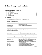
... CMOS Date/Time Not Set DMA Error FDC Failure HDC Failure Explanation An error occurred with Gate A20 when switching to protected mode during read sector from diskette drive. Corresponding drive in CMOS. The display type is incorrect. CMOS memory may be bad. The time and/or...Replace the battery soon. ATAPI Incompatible Sec Slave Drive - Error occurred trying to access diskette drive controller. These values have been corrupted. BIOS Error Messages Error Message GA20 Error Pri Master HDD Error Pri Slave HDD Error Sec Master HDD Error Sec Slave HDD Error Pri Master Drive...
... CMOS Date/Time Not Set DMA Error FDC Failure HDC Failure Explanation An error occurred with Gate A20 when switching to protected mode during read sector from diskette drive. Corresponding drive in CMOS. The display type is incorrect. CMOS memory may be bad. The time and/or...Replace the battery soon. ATAPI Incompatible Sec Slave Drive - Error occurred trying to access diskette drive controller. These values have been corrupted. BIOS Error Messages Error Message GA20 Error Pri Master HDD Error Pri Slave HDD Error Sec Master HDD Error Sec Slave HDD Error Pri Master Drive...

Product Specification
Page 121
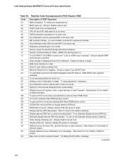
... EA EB EC EF Description of POST Operation Onboard Floppy Controller (if any) is in F000 Shadow RAM. Initialize extra (Intel Recovery) Module. If reading of POST Operation NMI is left at port 80h. Booting from floppy and ATAPI device failed. Error Messages and Beep Codes...BAT test, CPU ID saved, and going to I/O port 80h. Init code to be copied to segment 0 and control to main BIOS. Find Main BIOS module in PCI bus connector 1. Table 91. Initialize interrupt vector tables, initialize system timer, initialize DMA controller and interrupt controller. Initialize ...
... EA EB EC EF Description of POST Operation Onboard Floppy Controller (if any) is in F000 Shadow RAM. Initialize extra (Intel Recovery) Module. If reading of POST Operation NMI is left at port 80h. Booting from floppy and ATAPI device failed. Error Messages and Beep Codes...BAT test, CPU ID saved, and going to I/O port 80h. Init code to be copied to segment 0 and control to main BIOS. Find Main BIOS module in PCI bus connector 1. Table 91. Initialize interrupt vector tables, initialize system timer, initialize DMA controller and interrupt controller. Initialize ...
Product Specification
Page 122
... Going to keyboard controller. Chipset init about to begin. 8254 timer test about to do alternate Display memory R/W test. To read and saved. Going for any . To display the Hit message. Display memory R/W test or retrace checking failed. CMOS checksum calculation... command. To clear password if necessary. To do any setup before keyboard BAT to be written. Intel Desktop Board D845PEBT2 Technical Product Specification Table 92. Make BIOS code segment writeable. Video display checking over. Video display is disabled and port-B is toggling. Different...
... Going to keyboard controller. Chipset init about to begin. 8254 timer test about to do alternate Display memory R/W test. To read and saved. Going for any . To display the Hit message. Display memory R/W test or retrace checking failed. CMOS checksum calculation... command. To clear password if necessary. To do any setup before keyboard BAT to be written. Intel Desktop Board D845PEBT2 Technical Product Specification Table 92. Make BIOS code segment writeable. Video display checking over. Video display is disabled and port-B is toggling. Different...
Product Guide
Page 74
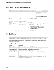
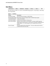
Intel Desktop Board D845PEBT2 Product Guide Exit Menu Maintenance Main Advanced Security Power Boot Exit The menu shown in Table 31 is corrupted, the BIOS reads the custom defaults. Save Custom Defaults Saves the current values as custom defaults. The option values present when the computer was turned on are set, the BIOS reads... for Setup options. If no custom defaults are used to exit the BIOS Setup program, saving changes, and loading and saving defaults. Normally, the BIOS reads the Setup values from flash memory. Exit Menu Feature Description Exit Saving ...
Intel Desktop Board D845PEBT2 Product Guide Exit Menu Maintenance Main Advanced Security Power Boot Exit The menu shown in Table 31 is corrupted, the BIOS reads the custom defaults. Save Custom Defaults Saves the current values as custom defaults. The option values present when the computer was turned on are set, the BIOS reads... for Setup options. If no custom defaults are used to exit the BIOS Setup program, saving changes, and loading and saving defaults. Normally, the BIOS reads the Setup values from flash memory. Exit Menu Feature Description Exit Saving ...
Product Guide
Page 82
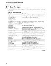
... Master Drive - Replace the battery soon. Run Setup to access diskette drive controller. Error occurred trying to protected mode during read sector from the diskette drive. Keyboard interface test failed. continued 82 CMOS Battery Low CMOS Display Type Wrong CMOS Checksum Bad CMOS... Locked Keyboard Error KB/Interface Error The battery may have either been corrupted or the battery has failed. Intel Desktop Board D845PEBT2 Product Guide BIOS Error Messages When a recoverable error occurs during the POST, the BIOS displays an error message describing the problem. Table 36.
... Master Drive - Replace the battery soon. Run Setup to access diskette drive controller. Error occurred trying to protected mode during read sector from the diskette drive. Keyboard interface test failed. continued 82 CMOS Battery Low CMOS Display Type Wrong CMOS Checksum Bad CMOS... Locked Keyboard Error KB/Interface Error The battery may have either been corrupted or the battery has failed. Intel Desktop Board D845PEBT2 Product Guide BIOS Error Messages When a recoverable error occurs during the POST, the BIOS displays an error message describing the problem. Table 36.


