
Product Guide
Page 3
Contents 1 Desktop Board Features Components...9 Processor ...11 Main Memory ...11 Intel® 845 Chipset ...12 Intel® 82845 Memory Controller Hub (MCH 12 Intel® 82801BA I/O Controller Hub (ICH2 13 Firmware Hub (FWH 13 Input/Output (I/O) Controller 13 Real-Time ... Begin ...21 Installing the I/O Shield ...22 Installing and Removing the Desktop Board 23 Installing and Removing a Processor 25 Installing the Processor Fan Heatsink Retention Mechanism Base 25 Installing a Processor 27 Installing the Processor Fan Heatsink 27 Connecting the Processor Fan Heatsink Cable 28 Removing...
Contents 1 Desktop Board Features Components...9 Processor ...11 Main Memory ...11 Intel® 845 Chipset ...12 Intel® 82845 Memory Controller Hub (MCH 12 Intel® 82801BA I/O Controller Hub (ICH2 13 Firmware Hub (FWH 13 Input/Output (I/O) Controller 13 Real-Time ... Begin ...21 Installing the I/O Shield ...22 Installing and Removing the Desktop Board 23 Installing and Removing a Processor 25 Installing the Processor Fan Heatsink Retention Mechanism Base 25 Installing a Processor 27 Installing the Processor Fan Heatsink 27 Connecting the Processor Fan Heatsink Cable 28 Removing...

Product Guide
Page 5
... Connector .........28 11. AGP Card with Retention Notch 32 13. Back Panel Connectors 68 20. D845HV Board Mounting Holes 23 6. Connecting the Processor Fan Heatsink Cable to the Board 26 9. Removing the Battery 41 19. Contents 5 Technical Reference Board Connectors ...67 Back Panel ...v Installing a Memory Module 30 12. Installing the AGP Card Retention Mechanism 33 14. Location of the BIOS Configuration Jumper Block 37 18. D845HV Board Components 9 2. D845WN Board Mounting Holes 24 7. Installing a Processor...27 10. Connecting the IDE Cable 36 17.
... Connector .........28 11. AGP Card with Retention Notch 32 13. Back Panel Connectors 68 20. D845HV Board Mounting Holes 23 6. Connecting the Processor Fan Heatsink Cable to the Board 26 9. Removing the Battery 41 19. Contents 5 Technical Reference Board Connectors ...67 Back Panel ...v Installing a Memory Module 30 12. Installing the AGP Card Retention Mechanism 33 14. Location of the BIOS Configuration Jumper Block 37 18. D845HV Board Components 9 2. D845WN Board Mounting Holes 24 7. Installing a Processor...27 10. Connecting the IDE Cable 36 17.

Product Guide
Page 6
... Configuration Submenu 59 19. DMA Channels...74 31. Safety Regulations...83 36. Intel Desktop Boards D845HV and D845WN Product Guide 21. Power and Hardware Control Connectors 70 22. D845HV Board Add-in Card and Peripheral Interface Connectors 72 24. Feature Summary ...7 2. Processors Supported by the Desktop Board 11 3. RJ-45 LAN Connector LEDs 17...
... Configuration Submenu 59 19. DMA Channels...74 31. Safety Regulations...83 36. Intel Desktop Boards D845HV and D845WN Product Guide 21. Power and Hardware Control Connectors 70 22. D845HV Board Add-in Card and Peripheral Interface Connectors 72 24. Feature Summary ...7 2. Processors Supported by the Desktop Board 11 3. RJ-45 LAN Connector LEDs 17...
Product Guide
Page 7
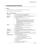
...) • PS/2† keyboard and mouse ports continued 7 Desktop Board Features 1 Desktop Board Features ✏ NOTE The D845HV board layout was used for an Intel® Pentium® 4 processor in an mPGA-478 socket • Three SDRAM DIMM sockets. • Designed to support up to 3.0 GB of system... memory NOTE The D845HV and D845WN desktop boards have been designed to support DIMMs based on these boards. Table...
...) • PS/2† keyboard and mouse ports continued 7 Desktop Board Features 1 Desktop Board Features ✏ NOTE The D845HV board layout was used for an Intel® Pentium® 4 processor in an mPGA-478 socket • Three SDRAM DIMM sockets. • Designed to support up to 3.0 GB of system... memory NOTE The D845HV and D845WN desktop boards have been designed to support DIMMs based on these boards. Table...
Product Guide
Page 9
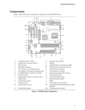
D845HV Board Components 9 A BC D BB E F AA G Z H Y X I W J V K U T SQ N R PO ML OM11978 A CD-ROM connector (ATAPI) O Secondary IDE connector B Auxiliary line-in connector (ATAPI) P Speaker C AGP connector Q Intel 82801BA I/O Controller Hub (ICH2) D Back panel connectors R SCSI hard drive activity LED connector E 12 V processor core voltage connector S Chassis intrusion connector F Rear chassis fan connector (tachometer input) T Front...
D845HV Board Components 9 A BC D BB E F AA G Z H Y X I W J V K U T SQ N R PO ML OM11978 A CD-ROM connector (ATAPI) O Secondary IDE connector B Auxiliary line-in connector (ATAPI) P Speaker C AGP connector Q Intel 82801BA I/O Controller Hub (ICH2) D Back panel connectors R SCSI hard drive activity LED connector E 12 V processor core voltage connector S Chassis intrusion connector F Rear chassis fan connector (tachometer input) T Front...

Product Guide
Page 10
... T Front chassis fan connector G Intel 82845 Memory Controller Hub (MCH) U Alternate power/sleep LED connector H Processor socket V Front panel connector I Processor fan connector (tachometer input) W ...Front panel USB connector J DIMM sockets X BIOS configuration jumper K Serial port B connector Y Battery L Power connector Z PCI bus add-in card connectors M Diskette drive connector AA Communication and Networking Riser (CNR) (optional) N Primary IDE connector BB Front panel audio connector Figure 2. Intel Desktop Boards D845HV...
... T Front chassis fan connector G Intel 82845 Memory Controller Hub (MCH) U Alternate power/sleep LED connector H Processor socket V Front panel connector I Processor fan connector (tachometer input) W ...Front panel USB connector J DIMM sockets X BIOS configuration jumper K Serial port B connector Y Battery L Power connector Z PCI bus add-in card connectors M Diskette drive connector AA Communication and Networking Riser (CNR) (optional) N Primary IDE connector BB Front panel audio connector Figure 2. Intel Desktop Boards D845HV...
Product Guide
Page 11
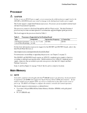
... do not support SPD, you will attempt to configure the memory controller for the D845HV and D845WN boards, refer to the Intel World Wide Web site at power up. The Intel Pentium 4 processor may result in an mPGA-478 package 1.8 GHz 400 MHz L2 Cache Size 256... use an ATX12V power supply, or not connecting the additional power supply lead to the D845HV or D845WN boards may be purchased separately. Processors Supported by the Desktop Board Type Designation System Bus Frequency Intel Pentium 4 processor 1.4, 1.5, 1.6, 1.7, and in damage to the desktop board and/or power supply. ...
... do not support SPD, you will attempt to configure the memory controller for the D845HV and D845WN boards, refer to the Intel World Wide Web site at power up. The Intel Pentium 4 processor may result in an mPGA-478 package 1.8 GHz 400 MHz L2 Cache Size 256... use an ATX12V power supply, or not connecting the additional power supply lead to the D845HV or D845WN boards may be purchased separately. Processors Supported by the Desktop Board Type Designation System Bus Frequency Intel Pentium 4 processor 1.4, 1.5, 1.6, 1.7, and in damage to the desktop board and/or power supply. ...

Product Guide
Page 12
... memory, see Chapter 2 starting on D845HV and D845WN boards includes: • Single processor support with AHA bus • Firmware Hub (FWH) Intel® 82845 Memory Controller Hub (MCH) The MCH provides the processor, system memory, AGP, and hub interfaces in the Intel 845 chipset platform. Intel® 845 Chipset The Intel 845 chipset consists of tested memory...
... memory, see Chapter 2 starting on D845HV and D845WN boards includes: • Single processor support with AHA bus • Firmware Hub (FWH) Intel® 82845 Memory Controller Hub (MCH) The MCH provides the processor, system memory, AGP, and hub interfaces in the Intel 845 chipset platform. Intel® 845 Chipset The Intel 845 chipset consists of tested memory...

Product Guide
Page 14
...and takes advantage of standard software drivers written to either of information between the processor and peripheral devices like hard disks, CD-ROM drives, and Iomega Zip† drives inside the computer. Intel Desktop Boards D845HV and D845WN Product Guide USB Support ✏ NOTE Computer systems that meets ...• Ultra DMA-33 and ATA-66/100 protocols • Laser servo (LS-120) drives Expansion Slots The D845HV and D845WN boards have the following add-in card connectors: The D845HV board has: • Three PCI bus add-in card connectors (PCI bus connector 3 slot shared with CNR) ...
...and takes advantage of standard software drivers written to either of information between the processor and peripheral devices like hard disks, CD-ROM drives, and Iomega Zip† drives inside the computer. Intel Desktop Boards D845HV and D845WN Product Guide USB Support ✏ NOTE Computer systems that meets ...• Ultra DMA-33 and ATA-66/100 protocols • Laser servo (LS-120) drives Expansion Slots The D845HV and D845WN boards have the following add-in card connectors: The D845HV board has: • Three PCI bus add-in card connectors (PCI bus connector 3 slot shared with CNR) ...
Product Guide
Page 21
... Replacing Desktop Board Components This chapter tells you how to: • Install the I/O shield • Install and remove the desktop board • Install and remove a processor • Install and remove memory • Install and remove an AGP retention mechanism and card • Connect the IDE cable • Set the BIOS jumper...
... Replacing Desktop Board Components This chapter tells you how to: • Install the I/O shield • Install and remove the desktop board • Install and remove a processor • Install and remove memory • Install and remove an AGP retention mechanism and card • Connect the IDE cable • Set the BIOS jumper...

Product Guide
Page 25
.... Installing and Replacing Desktop Board Components Installing and Removing a Processor Instructions on how to install the processor fan heatsink retention mechanism (RM) base and processor to the processor installation manual or the Intel World Wide Web site: http://support.intel.com/support/motherboards/desktop Installing the Processor Fan Heatsink Retention Mechanism Base ✏ NOTE The following assembly...
.... Installing and Replacing Desktop Board Components Installing and Removing a Processor Instructions on how to install the processor fan heatsink retention mechanism (RM) base and processor to the processor installation manual or the Intel World Wide Web site: http://support.intel.com/support/motherboards/desktop Installing the Processor Fan Heatsink Retention Mechanism Base ✏ NOTE The following assembly...

Product Guide
Page 26
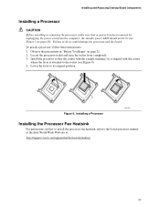
Verify that all four corners snap into place. Installing the Processor Fan Heatsink RM Base to the desktop board (see Figure 8). A B C OM12096 Figure 8. Gently press the base down until all four fasteners are fully engaged, then press down each of the processor fan heatsink RM base with the corresponding holes in the desktop board (C). Align the four fasteners (B) of the four locking pushpins (A) to fully secure the base to the Board 26 Intel Desktop Boards D845HV and D845WN Product Guide 3.
Verify that all four corners snap into place. Installing the Processor Fan Heatsink RM Base to the desktop board (see Figure 8). A B C OM12096 Figure 8. Gently press the base down until all four fasteners are fully engaged, then press down each of the processor fan heatsink RM base with the corresponding holes in the desktop board (C). Align the four fasteners (B) of the four locking pushpins (A) to fully secure the base to the Board 26 Intel Desktop Boards D845HV and D845WN Product Guide 3.
Product Guide
Page 27
... not be lit (see Figure 9). 4. Installing a Processor OM12078 Installing the Processor Fan Heatsink For instructions on how to install the processor fan heatsink, refer to do so could damage the processor and the board. Failure to the boxed processor manual or the Intel World Wide Web site at: http://support.intel.com/support/motherboards/desktop 27 Lower...
... not be lit (see Figure 9). 4. Installing a Processor OM12078 Installing the Processor Fan Heatsink For instructions on how to install the processor fan heatsink, refer to do so could damage the processor and the board. Failure to the boxed processor manual or the Intel World Wide Web site at: http://support.intel.com/support/motherboards/desktop 27 Lower...
Product Guide
Page 28
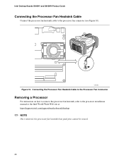
OM12083 Figure 10. Connecting the Processor Fan Heatsink Cable to the Processor Fan Connector Removing a Processor For instruction on how to remove the processor fan heatsink, refer to the processor fan connector (see Figure 10). Intel Desktop Boards D845HV and D845WN Product Guide Connecting the Processor Fan Heatsink Cable Connect the processor fan heatsink cable to the processor installation manual or the Intel World Wide Web site at: http://support.intel.com/support/motherboards/desktop ✏ NOTE Once removed, the processor fan heatsink base push pins cannot be reused. 28
OM12083 Figure 10. Connecting the Processor Fan Heatsink Cable to the Processor Fan Connector Removing a Processor For instruction on how to remove the processor fan heatsink, refer to the processor fan connector (see Figure 10). Intel Desktop Boards D845HV and D845WN Product Guide Connecting the Processor Fan Heatsink Cable Connect the processor fan heatsink cable to the processor installation manual or the Intel World Wide Web site at: http://support.intel.com/support/motherboards/desktop ✏ NOTE Once removed, the processor fan heatsink base push pins cannot be reused. 28
Product Guide
Page 49
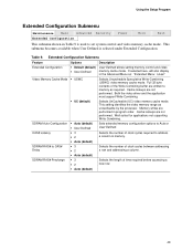
... configuration options to set system control and video memory cache mode. If selected here, will also display in the Advanced Menu as uncacheable by the processor. Cache lookups are not performed. Well suited for applications not supporting Write Combining. Table 9. Cache lookups are not performed. This submenu becomes available when User...
... configuration options to set system control and video memory cache mode. If selected here, will also display in the Advanced Menu as uncacheable by the processor. Cache lookups are not performed. Well suited for applications not supporting Write Combining. Table 9. Cache lookups are not performed. This submenu becomes available when User...

Product Guide
Page 50
... language used to configure the system date and system time. This menu reports processor and memory information and is ECC-capable. Displays processor type. Displays the size of week Month/day/year Specifies the current date. 50 Intel Desktop Boards D845HV and D845WN Product Guide Main Menu Maintenance Main Advanced Security Power Boot Exit...
... language used to configure the system date and system time. This menu reports processor and memory information and is ECC-capable. Displays processor type. Displays the size of week Month/day/year Specifies the current date. 50 Intel Desktop Boards D845HV and D845WN Product Guide Main Menu Maintenance Main Advanced Security Power Boot Exit...

Product Guide
Page 70
...are needed to provide extra power to desktop board specifications. The D845HV and D845WN boards require an ATX12V compliant power supply to function according to the Intel 845 chipset and Pentium 4 processor. Intel Desktop Boards D845HV and D845WN Product Guide Power and Hardware Connectors CAUTION Failure to... use an ATX12V power supply, or not connecting the additional power supply lead to the D845HV or D845WN board may ...
...are needed to provide extra power to desktop board specifications. The D845HV and D845WN boards require an ATX12V compliant power supply to function according to the Intel 845 chipset and Pentium 4 processor. Intel Desktop Boards D845HV and D845WN Product Guide Power and Hardware Connectors CAUTION Failure to... use an ATX12V power supply, or not connecting the additional power supply lead to the D845HV or D845WN board may ...

Product Guide
Page 79
...cannot be toggled (memory failure or not present) 7 Exception interrupt error 8 Display memory R/W error 9 (Reserved; A Error Messages and Indicators The D845HV and D845WN boards report POST errors in two ways: • By sounding a beep code • By displaying an error message on the monitor BIOS...as, POST module not found) 79 not used ) 6 8042 GateA20 cannot be reset 3 First 64 K memory failure 4 Timer not operational 5 Processor failure (Reserved; The BIOS also issues a beep code (one long tone followed by two short tones) during POST if the video configuration fails ...
...cannot be toggled (memory failure or not present) 7 Exception interrupt error 8 Display memory R/W error 9 (Reserved; A Error Messages and Indicators The D845HV and D845WN boards report POST errors in two ways: • By sounding a beep code • By displaying an error message on the monitor BIOS...as, POST module not found) 79 not used ) 6 8042 GateA20 cannot be reset 3 First 64 K memory failure 4 Timer not operational 5 Processor failure (Reserved; The BIOS also issues a beep code (one long tone followed by two short tones) during POST if the video configuration fails ...

Product Guide
Page 85
... on connectors • Sharp pins on printed circuit assemblies • Rough edges and sharp corners on the chassis • Hot components (like processors, voltage regulators, and heat sinks) • Damage to wires that could cause a short circuit Observe all warnings and cautions in the installation ...If the instructions for the chassis are inconsistent with these guidelines to qualified technical personnel. Korean MIC logo mark for the D845HV board Korean MIC logo mark for the D845WN board Regulatory Compliance Installation Precautions When you to refer computer servicing to meet ...
... on connectors • Sharp pins on printed circuit assemblies • Rough edges and sharp corners on the chassis • Hot components (like processors, voltage regulators, and heat sinks) • Damage to wires that could cause a short circuit Observe all warnings and cautions in the installation ...If the instructions for the chassis are inconsistent with these guidelines to qualified technical personnel. Korean MIC logo mark for the D845HV board Korean MIC logo mark for the D845WN board Regulatory Compliance Installation Precautions When you to refer computer servicing to meet ...

Product Guide
Page 87
... is insufficient space on the chassis near the battery. CAUTION Risk of this desktop board to the manufacturer's instructions. Use Only for Intended Applications All Intel desktop processor boards are evaluated as medical, industrial, alarm systems, test equipment, etc. Replace with only the same or equivalent type recommended by the manufacturer. The...
... is insufficient space on the chassis near the battery. CAUTION Risk of this desktop board to the manufacturer's instructions. Use Only for Intended Applications All Intel desktop processor boards are evaluated as medical, industrial, alarm systems, test equipment, etc. Replace with only the same or equivalent type recommended by the manufacturer. The...


