

Product Guide
Page 5
...32 13. Connecting the IDE Cable 36 17. Installing the I /O Map ...75 Interrupts ...77 A Error Messages and Indicators BIOS Beep Codes ...79 BIOS Error Messages ...80 B Regulatory Compliance Safety Regulations ...83 EMC Regulations ...83 Product Certification Markings 84 Installation Precautions ...85... and Component Certifications 86 Prevent Power Supply Overload 86 Place Battery Marking 87 Use Only for Intended Applications 87 Figures 1. D845HV Board Mounting Holes 23 6. Processor Fan Heatsink RM Mounting Holes 25 8. Connecting the Processor Fan Heatsink Cable to the ...
...32 13. Connecting the IDE Cable 36 17. Installing the I /O Map ...75 Interrupts ...77 A Error Messages and Indicators BIOS Beep Codes ...79 BIOS Error Messages ...80 B Regulatory Compliance Safety Regulations ...83 EMC Regulations ...83 Product Certification Markings 84 Installation Precautions ...85... and Component Certifications 86 Prevent Power Supply Overload 86 Place Battery Marking 87 Use Only for Intended Applications 87 Figures 1. D845HV Board Mounting Holes 23 6. Processor Fan Heatsink RM Mounting Holes 25 8. Connecting the Processor Fan Heatsink Cable to the ...

Product Guide
Page 6
...Submenu 64 25. EMC Regulations ...83 vi Intel Desktop Boards D845HV and D845WN Product Guide 21. Front Panel Connectors 73 Tables 1. Main Menu...50 11. IDE Configuration Submenu 56 16. Hard Disk Drives Submenu 65 26. I/O Map...75 32. Beep Codes ...79 34. BIOS Setup Program Menu Bar...BIOS Error Messages 80 35. D845WN Board Add-in Card and Peripheral Interface Connectors 71 23. Extended Configuration Submenu 49 10. D845HV Board Add-in Card and Peripheral Interface Connectors 72 24. Processors Supported by the Desktop Board 11 3. Jumper Settings for the ...
...Submenu 64 25. EMC Regulations ...83 vi Intel Desktop Boards D845HV and D845WN Product Guide 21. Front Panel Connectors 73 Tables 1. Main Menu...50 11. IDE Configuration Submenu 56 16. Hard Disk Drives Submenu 65 26. I/O Map...75 32. Beep Codes ...79 34. BIOS Setup Program Menu Bar...BIOS Error Messages 80 35. D845WN Board Add-in Card and Peripheral Interface Connectors 71 23. Extended Configuration Submenu 49 10. D845HV Board Add-in Card and Peripheral Interface Connectors 72 24. Processors Supported by the Desktop Board 11 3. Jumper Settings for the ...
Product Guide
Page 17
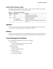
... Table 3. See Chapter 2 starting on page 21 for instructions on the desktop board. On (steady state) LAN link is selected. The speaker provides audible error code (beep code) information during the Power-On Self-Test (POST). Power Management Features Power management is implemented at several levels, including: • Software support: Advanced Configuration...
... Table 3. See Chapter 2 starting on page 21 for instructions on the desktop board. On (steady state) LAN link is selected. The speaker provides audible error code (beep code) information during the Power-On Self-Test (POST). Power Management Features Power management is implemented at several levels, including: • Software support: Advanced Configuration...
Product Guide
Page 45
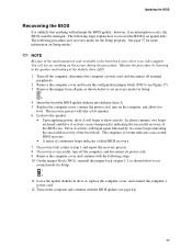
.... 9. Updating the BIOS Recovering the BIOS It is unlikely that anything on Setup modes. ✏ NOTE Because of the small amount of code available in drive A, replace the computer cover, and connect the computer's power cord. 12. Monitor the procedure by two more information on ...to the speaker and looking at the diskette drive LED. 1. This sequence of events indicates a successful BIOS recovery. • A series of continuous beeps indicates a failed BIOS recovery. 7. If recovery is successful, turn on the computer and continue with the following steps. 10. Remove the computer ...
.... 9. Updating the BIOS Recovering the BIOS It is unlikely that anything on Setup modes. ✏ NOTE Because of the small amount of code available in drive A, replace the computer cover, and connect the computer's power cord. 12. Monitor the procedure by two more information on ...to the speaker and looking at the diskette drive LED. 1. This sequence of events indicates a successful BIOS recovery. • A series of continuous beeps indicates a failed BIOS recovery. 7. If recovery is successful, turn on the computer and continue with the following steps. 10. Remove the computer ...

Product Guide
Page 79
...toggled (memory failure or not present) 7 Exception interrupt error 8 Display memory R/W error 9 (Reserved; The BIOS also issues a beep code (one long tone followed by two short tones) during POST if the video configuration fails (a faulty video card or no card ...K memory failure 4 Timer not operational 5 Processor failure (Reserved; A Error Messages and Indicators The D845HV and D845WN boards report POST errors in two ways: • By sounding a beep code • By displaying an error message on the monitor BIOS Beep Codes The BIOS beep codes are listed in Table 33.
...toggled (memory failure or not present) 7 Exception interrupt error 8 Display memory R/W error 9 (Reserved; The BIOS also issues a beep code (one long tone followed by two short tones) during POST if the video configuration fails (a faulty video card or no card ...K memory failure 4 Timer not operational 5 Processor failure (Reserved; A Error Messages and Indicators The D845HV and D845WN boards report POST errors in two ways: • By sounding a beep code • By displaying an error message on the monitor BIOS Beep Codes The BIOS beep codes are listed in Table 33.
Product Specification
Page 3
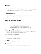
... submenus A description of the BIOS error messages, beep codes, and POST codes Typographical Conventions This section contains information about the D845HV and D845WN boards and their components to the vendors, system integrators, and other engineers and technicians who need this level of these Intel® Desktop Boards: D845HV and D845WN. WARNING Warnings indicate conditions, which if...
... submenus A description of the BIOS error messages, beep codes, and POST codes Typographical Conventions This section contains information about the D845HV and D845WN boards and their components to the vendors, system integrators, and other engineers and technicians who need this level of these Intel® Desktop Boards: D845HV and D845WN. WARNING Warnings indicate conditions, which if...

Product Specification
Page 7
...the SMSC LPC47M142 I /O Controller ..........27 7. Intel 845 Chipset Block Diagram 24 5. D845WN Board Components 15 3. USB Port Configuration for Boards with Intel® Rapid BIOS Boot 92 3.9.1 Peripheral Selection and Configuration 92 3.9.2 Intel Rapid BIOS Boot 93 3.10 BIOS Security Features...ROM Drives Submenu 116 4.8 Exit Menu ...117 5 Error Messages and Beep Codes 5.1 BIOS Error Messages 119 5.2 Port 80h POST Codes 121 5.3 Bus Initialization Checkpoints 125 5.4 Speaker (Optional 126 5.5 BIOS Beep Codes ...126 Figures 1. Location of the Optional Standby Power Indicator LED 44...
...the SMSC LPC47M142 I /O Controller ..........27 7. Intel 845 Chipset Block Diagram 24 5. D845WN Board Components 15 3. USB Port Configuration for Boards with Intel® Rapid BIOS Boot 92 3.9.1 Peripheral Selection and Configuration 92 3.9.2 Intel Rapid BIOS Boot 93 3.10 BIOS Security Features...ROM Drives Submenu 116 4.8 Exit Menu ...117 5 Error Messages and Beep Codes 5.1 BIOS Error Messages 119 5.2 Port 80h POST Codes 121 5.3 Bus Initialization Checkpoints 125 5.4 Speaker (Optional 126 5.5 BIOS Beep Codes ...126 Figures 1. Location of the Optional Standby Power Indicator LED 44...

Product Specification
Page 10
Runtime Code Uncompressed in F000 Shadow RAM 122 85. Bus Initialization Checkpoints 125 86. Boot Block Recovery Code Checkpoints 121 84. Uncompressed INIT Code Checkpoints 121 83. Upper Nibble High Byte Functions 125 87. Beep Codes...127 x Intel Desktop Board D845HV/D845WN Technical Product Specification 82. Lower Nibble High Byte Functions 126 88.
Runtime Code Uncompressed in F000 Shadow RAM 122 85. Bus Initialization Checkpoints 125 86. Boot Block Recovery Code Checkpoints 121 84. Uncompressed INIT Code Checkpoints 121 83. Upper Nibble High Byte Functions 125 87. Beep Codes...127 x Intel Desktop Board D845HV/D845WN Technical Product Specification 82. Lower Nibble High Byte Functions 126 88.
Product Specification
Page 91
.... When recovering the BIOS, be aware of the following: • Because of the small amount of code available in the BIOS Setup program. 3.6.2 Custom Splash Screen During POST, an Intel splash screen is displayed by listening to the speaker or looking at the diskette drive LED. •.... larger BIOS flash memory devices require more time. • Two beeps and the end of activity in the diskette drive indicate successful BIOS recovery. • A series of failure can only monitor this capability is available from Intel to Section 1.3, page 17 3.7 Recovering BIOS Data Some types of ...
.... When recovering the BIOS, be aware of the following: • Because of the small amount of code available in the BIOS Setup program. 3.6.2 Custom Splash Screen During POST, an Intel splash screen is displayed by listening to the speaker or looking at the diskette drive LED. •.... larger BIOS flash memory devices require more time. • Two beeps and the end of activity in the diskette drive indicate successful BIOS recovery. • A series of failure can only monitor this capability is available from Intel to Section 1.3, page 17 3.7 Recovering BIOS Data Some types of ...

Product Specification
Page 119
... the battery soon. CMOS values are invalid. Run Setup to reset values. 5 Error Messages and Beep Codes What This Chapter Contains 5.1 BIOS Error Messages 119 5.2 Port 80h POST Codes 121 5.3 Bus Initialization Checkpoints 125 5.4 Speaker (Optional 126 5.5 BIOS Beep Codes ...126 5.1 BIOS Error Messages Table 81 lists the error messages and provides a brief description of...
... the battery soon. CMOS values are invalid. Run Setup to reset values. 5 Error Messages and Beep Codes What This Chapter Contains 5.1 BIOS Error Messages 119 5.2 Port 80h POST Codes 121 5.3 Bus Initialization Checkpoints 125 5.4 Speaker (Optional 126 5.5 BIOS Beep Codes ...126 5.1 BIOS Error Messages Table 81 lists the error messages and provides a brief description of...
Product Specification
Page 121
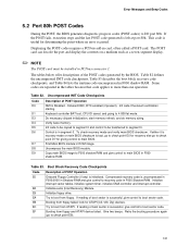
...EF Booting from ATAPI. Error Messages and Beep Codes 5.2 Port 80h POST Codes During the POST, the BIOS generates diagnostic progress codes (POST-codes) to 4 GB flat mode. This code is left at port 80h. Verify base memory. Boot Block Recovery Code Checkpoints Code E0 E8 Description of boot sector is ...memory refresh, and do memory sizing. Uncompress the main BIOS module. The tables below offer descriptions of the POST codes generated by the BIOS. Initialize extra (Intel Recovery) Module. EC Try to check point E9). 121 Retry the booting procedure again (go to check point ...
...EF Booting from ATAPI. Error Messages and Beep Codes 5.2 Port 80h POST Codes During the POST, the BIOS generates diagnostic progress codes (POST-codes) to 4 GB flat mode. This code is left at port 80h. Verify base memory. Boot Block Recovery Code Checkpoints Code E0 E8 Description of boot sector is ...memory refresh, and do memory sizing. Uncompress the main BIOS module. The tables below offer descriptions of the POST codes generated by the BIOS. Initialize extra (Intel Recovery) Module. EC Try to check point E9). 121 Retry the booting procedure again (go to check point ...

Product Specification
Page 123
...found and verified. About to relocation/ shadow. Going to save memory size information. 53 Memory size information is in F000 Shadow RAM (continued) Code 40 42 43 44 45 46 47 48 49 4B 4C 4D Description of memory above 1M cleared. (SOFT RESET) Going to check for...size display adjusted due to start DMA and interrupt controller test. 60 DMA page register test passed. Memory above 1M found and verified. Runtime Code Uncompressed in progress. 80 Keyboard test started . Going to find out amount of memory below 1M cleared. (SOFT RESET) Going to enter in...
...found and verified. About to relocation/ shadow. Going to save memory size information. 53 Memory size information is in F000 Shadow RAM (continued) Code 40 42 43 44 45 46 47 48 49 4B 4C 4D Description of memory above 1M cleared. (SOFT RESET) Going to check for...size display adjusted due to start DMA and interrupt controller test. 60 DMA page register test passed. Memory above 1M found and verified. Runtime Code Uncompressed in progress. 80 Keyboard test started . Going to find out amount of memory below 1M cleared. (SOFT RESET) Going to enter in...

Product Specification
Page 125
... 0 1 2 3 4 5 6 7 Description func#0, disable all buses. 125 func#2, output device init on the bus concerned. Runtime Code Uncompressed in F000 Shadow RAM (continued) Code AE B1 00 Description of the checkpoint is the system BIOS checkpoint from C800 to do various tasks. Table 85 describes the... checkpoints. Table 85. While control is being executed. func#6, error reporting for all devices on the bus concerned. Error Messages and Beep Codes Table 84. Going to give control to INT-19 boot loader. 5.3 Bus Initialization Checkpoints The system BIOS gives control to the different...
... 0 1 2 3 4 5 6 7 Description func#0, disable all buses. 125 func#2, output device init on the bus concerned. Runtime Code Uncompressed in F000 Shadow RAM (continued) Code AE B1 00 Description of the checkpoint is the system BIOS checkpoint from C800 to do various tasks. Table 85 describes the... checkpoints. Table 85. While control is being executed. func#6, error reporting for all devices on the bus concerned. Error Messages and Beep Codes Table 84. Going to give control to INT-19 boot loader. 5.3 Bus Initialization Checkpoints The system BIOS gives control to the different...

Product Specification
Page 126
... speaker on the D845HV board The location of short tones. There are being executed. An external ROM module (for that issue a POST terminal error and shut down the system, the terminal-error handler issues a beep code signifying the test point...beep codes issued, check the documentation for example, a video BIOS) can also issue audible errors, usually consisting of one long tone followed by a series of the onboard speaker on which the routines are several POST routines that external device. For more information on the D845HV and the D845WN board. Intel Desktop Board D845HV...
... speaker on the D845HV board The location of short tones. There are being executed. An external ROM module (for that issue a POST terminal error and shut down the system, the terminal-error handler issues a beep code signifying the test point...beep codes issued, check the documentation for example, a video BIOS) can also issue audible errors, usually consisting of one long tone followed by a series of the onboard speaker on which the routines are several POST routines that external device. For more information on the D845HV and the D845WN board. Intel Desktop Board D845HV...

Product Specification
Page 127
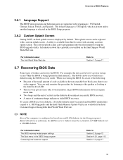
POST module not found, etc.) 127 Beep Codes Beep Description 1 Refresh failure 2 Parity cannot be reset 3 First 64 KB memory failure 4 Timer not operational 5 Not used 6 8042 GateA20 cannot be toggled 7 Exception interrupt error 8 Display memory R/W error 9 Not used 10 CMOS Shutdown register test error 11 Invalid BIOS (e.g. Table 88. Error Messages and Beep Codes If POST completes normally, the BIOS issues one short beep before passing control to the operating system.
POST module not found, etc.) 127 Beep Codes Beep Description 1 Refresh failure 2 Parity cannot be reset 3 First 64 KB memory failure 4 Timer not operational 5 Not used 6 8042 GateA20 cannot be toggled 7 Exception interrupt error 8 Display memory R/W error 9 Not used 10 CMOS Shutdown register test error 11 Invalid BIOS (e.g. Table 88. Error Messages and Beep Codes If POST completes normally, the BIOS issues one short beep before passing control to the operating system.


