
Product Guide
Page 3
Contents 1 Desktop Board Features Components...9 Processor ...11 Main Memory ...11 Intel® 845 Chipset ...12 Intel® 82845 Memory Controller Hub (MCH 12 Intel® 82801BA I/O Controller Hub (ICH2 13 Firmware Hub (FWH 13 Input/Output (I/O) Controller 13 Real-Time Clock...13 ...USB Support ...14 PCI Enhanced IDE Interface 14 Expansion Slots...14 Accelerated Graphics Port (AGP 15 Communication and Networking Riser (CNR) (Optional 15 Audio Subsystem ...15 BIOS...
Contents 1 Desktop Board Features Components...9 Processor ...11 Main Memory ...11 Intel® 845 Chipset ...12 Intel® 82845 Memory Controller Hub (MCH 12 Intel® 82801BA I/O Controller Hub (ICH2 13 Firmware Hub (FWH 13 Input/Output (I/O) Controller 13 Real-Time Clock...13 ...USB Support ...14 PCI Enhanced IDE Interface 14 Expansion Slots...14 Accelerated Graphics Port (AGP 15 Communication and Networking Riser (CNR) (Optional 15 Audio Subsystem ...15 BIOS...
Product Guide
Page 4
Intel Desktop Boards D845HV and D845WN Product Guide Installing and Removing Memory 29 DIMM Installation Guidelines 29 Installing DIMMs ...29 Removing DIMMs ...31 Installing and Removing the AGP Retention ... 37 Clearing Passwords ...38 Replacing the Battery ...39 3 Updating the BIOS Updating the BIOS with the Intel® Express BIOS Update Utility 43 Updating the BIOS with the Intel® Flash Memory Update Utility 44 Obtaining the BIOS Update File 44 Updating the BIOS...44 Recovering the BIOS 45 4 Using the Setup Program Maintenance Menu...48 Extended Configuration Submenu...
Intel Desktop Boards D845HV and D845WN Product Guide Installing and Removing Memory 29 DIMM Installation Guidelines 29 Installing DIMMs ...29 Removing DIMMs ...31 Installing and Removing the AGP Retention ... 37 Clearing Passwords ...38 Replacing the Battery ...39 3 Updating the BIOS Updating the BIOS with the Intel® Express BIOS Update Utility 43 Updating the BIOS with the Intel® Flash Memory Update Utility 44 Obtaining the BIOS Update File 44 Updating the BIOS...44 Recovering the BIOS 45 4 Using the Setup Program Maintenance Menu...48 Extended Configuration Submenu...

Product Guide
Page 5
...69 Front Panel Connectors 73 Desktop Board Resources 74 Memory Map ...74 DMA Channels ...74 I /O Shield 22 5. Location of the BIOS Configuration Jumper Block 37 18. Processor Fan Heatsink RM Mounting Holes 25 8. Installing the AGP Card Retention Mechanism 33 14. Connecting the... 36 17. Location of Standby Power Indicator 18 4. Removing the Battery 41 19. Audio Connectors ...69 v Back Panel Connectors 68 20. D845HV Board Components 9 2. AGP Card with Retention Notch 32 13. Connecting the Processor Fan Heatsink Cable to the Board 26 9. D845WN Board Components...
...69 Front Panel Connectors 73 Desktop Board Resources 74 Memory Map ...74 DMA Channels ...74 I /O Shield 22 5. Location of the BIOS Configuration Jumper Block 37 18. Processor Fan Heatsink RM Mounting Holes 25 8. Installing the AGP Card Retention Mechanism 33 14. Connecting the... 36 17. Location of Standby Power Indicator 18 4. Removing the Battery 41 19. Audio Connectors ...69 v Back Panel Connectors 68 20. D845HV Board Components 9 2. AGP Card with Retention Notch 32 13. Connecting the Processor Fan Heatsink Cable to the Board 26 9. D845WN Board Components...

Product Guide
Page 6
...29. DMA Channels...74 31. Interrupts ...77 33. Beep Codes ...79 34. Front Panel Connectors 73 Tables 1. Jumper Settings for the BIOS Setup Program Modes (J9G1 37 6. Boot Device Priority Submenu 64 25. Safety Regulations...83 36. D845WN Board Add-in Card and Peripheral ...CD-ROM Drives Submenu 66 28. I/O Map...75 32. BIOS Error Messages 80 35. Intel Desktop Boards D845HV and D845WN Product Guide 21. System Memory Map...74 30. D845HV Board Add-in Card and Peripheral Interface Connectors 72 24. BIOS Setup Program Menu Bar 47 7. Diskette Configuration Submenu 58 18...
...29. DMA Channels...74 31. Interrupts ...77 33. Beep Codes ...79 34. Front Panel Connectors 73 Tables 1. Jumper Settings for the BIOS Setup Program Modes (J9G1 37 6. Boot Device Priority Submenu 64 25. Safety Regulations...83 36. D845WN Board Add-in Card and Peripheral ...CD-ROM Drives Submenu 66 28. I/O Map...75 32. BIOS Error Messages 80 35. Intel Desktop Boards D845HV and D845WN Product Guide 21. System Memory Map...74 30. D845HV Board Add-in Card and Peripheral Interface Connectors 72 24. BIOS Setup Program Menu Bar 47 7. Diskette Configuration Submenu 58 18...
Product Guide
Page 8
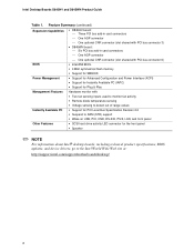
...add-in card connectors One AGP connector One optional CNR connector (slot shared with PCI bus connector 6) BIOS • Intel/AMI BIOS. • 4 Mbit symmetrical flash memory • Support for SMBIOS Power Management • Support for Advanced Configuration and Power... ✏ NOTE For information about Intel® desktop boards, including technical product specifications, BIOS updates, and device drivers, go to the Intel World Wide Web site at: http://support.intel.com/support/motherboards/desktop/ 8 Intel Desktop Boards D845HV and D845WN Product Guide Table 1.
...add-in card connectors One AGP connector One optional CNR connector (slot shared with PCI bus connector 6) BIOS • Intel/AMI BIOS. • 4 Mbit symmetrical flash memory • Support for SMBIOS Power Management • Support for Advanced Configuration and Power... ✏ NOTE For information about Intel® desktop boards, including technical product specifications, BIOS updates, and device drivers, go to the Intel World Wide Web site at: http://support.intel.com/support/motherboards/desktop/ 8 Intel Desktop Boards D845HV and D845WN Product Guide Table 1.
Product Guide
Page 9
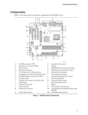
D845HV Board Components 9 A BC D BB E F AA G Z H Y X I W J V K U T SQ N R PO ML OM11978 A CD-ROM connector (ATAPI) O Secondary IDE connector B Auxiliary line-in connector (ATAPI) P Speaker C AGP connector Q Intel 82801BA I/O Controller Hub (ICH2) D Back panel connectors R SCSI hard... H Processor socket V Front panel connector I Processor fan connector (tachometer input) W Front panel USB connector J DIMM sockets X BIOS configuration jumper K Serial port B connector Y Battery L Power connector Z PCI bus add-in card connectors M Diskette drive connector ...
D845HV Board Components 9 A BC D BB E F AA G Z H Y X I W J V K U T SQ N R PO ML OM11978 A CD-ROM connector (ATAPI) O Secondary IDE connector B Auxiliary line-in connector (ATAPI) P Speaker C AGP connector Q Intel 82801BA I/O Controller Hub (ICH2) D Back panel connectors R SCSI hard... H Processor socket V Front panel connector I Processor fan connector (tachometer input) W Front panel USB connector J DIMM sockets X BIOS configuration jumper K Serial port B connector Y Battery L Power connector Z PCI bus add-in card connectors M Diskette drive connector ...

Product Guide
Page 10
...Intel Desktop Boards D845HV and D845WN Product Guide Figure 2 shows the location of the major components on the D845WN board. A BC D BB E F AA G Z H Y X I W J V K U T SQ N R PO ML OM12039 A CD-ROM connector (ATAPI) O Secondary IDE connector B Auxiliary line-in connector (ATAPI) P Speaker C AGP connector Q Intel... socket V Front panel connector I Processor fan connector (tachometer input) W Front panel USB connector J DIMM sockets X BIOS configuration jumper K Serial port B connector Y Battery L Power connector Z PCI bus add-in card connectors M Diskette ...
...Intel Desktop Boards D845HV and D845WN Product Guide Figure 2 shows the location of the major components on the D845WN board. A BC D BB E F AA G Z H Y X I W J V K U T SQ N R PO ML OM12039 A CD-ROM connector (ATAPI) O Secondary IDE connector B Auxiliary line-in connector (ATAPI) P Speaker C AGP connector Q Intel... socket V Front panel connector I Processor fan connector (tachometer input) W Front panel USB connector J DIMM sockets X BIOS configuration jumper K Serial port B connector Y Battery L Power connector Z PCI bus add-in card connectors M Diskette ...
Product Guide
Page 11
...your memory modules do not support SPD, you will attempt to configure the memory controller for the D845HV and D845WN boards, refer to the Intel World Wide Web site at: http://support.intel.com/support/motherboards/desktop/ For instructions on installing or upgrading the processor, see a notification to ... board supports the processors listed in Figure 21 on page 70 show the two power connector locations. The BIOS will see Chapter 2 on the screen at power up. The D845HV and D845WN boards require an ATX12V compliant power supply to function according to this effect on page 21.
...your memory modules do not support SPD, you will attempt to configure the memory controller for the D845HV and D845WN boards, refer to the Intel World Wide Web site at: http://support.intel.com/support/motherboards/desktop/ For instructions on installing or upgrading the processor, see a notification to ... board supports the processors listed in Figure 21 on page 70 show the two power connector locations. The BIOS will see Chapter 2 on the screen at power up. The D845HV and D845WN boards require an ATX12V compliant power supply to function according to this effect on page 21.

Product Guide
Page 13
...D845HV and D845WN boards includes: • Integrated IDE controller supports two Ultra DMA-33 and ATA-66/100 channels, BMIDE and PIO modes • SMBus interface • FWH interface • Low Pin Count (LPC) interface • AC'97 2.1 compliant link for audio and telephony CODECs • Integrated Intel...additional ports are provided by the I/O controller) Firmware Hub (FWH) The 4 Mbit Firmware Hub has these features: • System BIOS • System security and management logic Input/Output (I/O) Controller The SMSC LPC47M142 ultra I/O controller features the following: • Low ...
...D845HV and D845WN boards includes: • Integrated IDE controller supports two Ultra DMA-33 and ATA-66/100 channels, BMIDE and PIO modes • SMBus interface • FWH interface • Low Pin Count (LPC) interface • AC'97 2.1 compliant link for audio and telephony CODECs • Integrated Intel...additional ports are provided by the I/O controller) Firmware Hub (FWH) The 4 Mbit Firmware Hub has these features: • System BIOS • System security and management logic Input/Output (I/O) Controller The SMSC LPC47M142 ultra I/O controller features the following: • Low ...

Product Guide
Page 15
... If you install a PCI add-in Chapter 3 on page 43. Desktop Board Features Accelerated Graphics Port (AGP) ✏ NOTE The D845HV and D845WN boards are only compatible with retention notches (see Chapter 2 on page 21. AGP is independent of the PCI bus and is...speakers are available from Intel's World Wide Web site: http://support.intel.com/support/motherboards/desktop/ BIOS The BIOS provides the Power-On Self-Test (POST), the BIOS Setup program, the PCI and IDE auto-configuration utilities, and the video BIOS. The BIOS can be updated by following : • Intel 82801BA ICH2 •...
... If you install a PCI add-in Chapter 3 on page 43. Desktop Board Features Accelerated Graphics Port (AGP) ✏ NOTE The D845HV and D845WN boards are only compatible with retention notches (see Chapter 2 on page 21. AGP is independent of the PCI bus and is...speakers are available from Intel's World Wide Web site: http://support.intel.com/support/motherboards/desktop/ BIOS The BIOS provides the Power-On Self-Test (POST), the BIOS Setup program, the PCI and IDE auto-configuration utilities, and the video BIOS. The BIOS can be updated by following : • Intel 82801BA ICH2 •...
Product Guide
Page 16
...ATA-66/100 peripheral device • An ATA-66/100 compatible cable • ATA-66/100 operating system device drivers Security Passwords The BIOS includes security features that contains the MAC address LAN Subsystem Software For LAN software and drivers, refer to view and change all Setup options. ...If only the supervisor password is booted. If both 10Base-T and 100Base-TX connectivity. Intel Desktop Boards D845HV and D845WN Product Guide IDE Auto Configuration If you install an IDE device (such as a hard drive) in your computer. The password...
...ATA-66/100 peripheral device • An ATA-66/100 compatible cable • ATA-66/100 operating system device drivers Security Passwords The BIOS includes security features that contains the MAC address LAN Subsystem Software For LAN software and drivers, refer to view and change all Setup options. ...If only the supervisor password is booted. If both 10Base-T and 100Base-TX connectivity. Intel Desktop Boards D845HV and D845WN Product Guide IDE Auto Configuration If you install an IDE device (such as a hard drive) in your computer. The password...
Product Guide
Page 21
... remove a processor • Install and remove memory • Install and remove an AGP retention mechanism and card • Connect the IDE cable • Set the BIOS jumper • Clear passwords • Replace the battery Before You Begin CAUTION Before you install this board in a chassis, see Appendix B for using an antistatic...
... remove a processor • Install and remove memory • Install and remove an AGP retention mechanism and card • Connect the IDE cable • Set the BIOS jumper • Clear passwords • Replace the battery Before You Begin CAUTION Before you install this board in a chassis, see Appendix B for using an antistatic...
Product Guide
Page 37
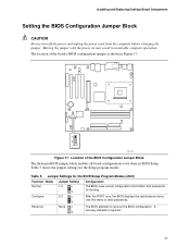
... 37 A recovery diskette is shown in Figure 17. 1 3 J9G1 OM11996 Figure 17. Installing and Replacing Desktop Board Components Setting the BIOS Configuration Jumper Block CAUTION Always turn off the power and unplug the power cord from the computer before changing the jumper. Table 5 shows ... for the Setup program modes. Table 5. Moving the jumper with the power on may result in BIOS Setup. The location of the BIOS Configuration Jumper Block The three-pin BIOS jumper block enables all board configurations to be done in unreliable computer operation. Use this menu to ...
... 37 A recovery diskette is shown in Figure 17. 1 3 J9G1 OM11996 Figure 17. Installing and Replacing Desktop Board Components Setting the BIOS Configuration Jumper Block CAUTION Always turn off the power and unplug the power cord from the computer before changing the jumper. Table 5 shows ... for the Setup program modes. Table 5. Moving the jumper with the power on may result in BIOS Setup. The location of the BIOS Configuration Jumper Block The three-pin BIOS jumper block enables all board configurations to be done in unreliable computer operation. Use this menu to ...
Product Guide
Page 39
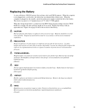
... Board Components Replacing the Battery A coin-cell battery (CR2032) powers the real-time clock and CMOS memory. When the voltage drops below a certain level, the BIOS Setup program settings stored in accordance with an incorrect type. Batterier bør om muligt genbruges.
... Board Components Replacing the Battery A coin-cell battery (CR2032) powers the real-time clock and CMOS memory. When the voltage drops below a certain level, the BIOS Setup program settings stored in accordance with an incorrect type. Batterier bør om muligt genbruges.

Product Guide
Page 43
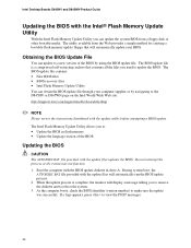
...-based installation wizards. 3 Updating the BIOS This chapter tells you how to update the BIOS by either using the Intel® Express BIOS Update utility or the Intel® Flash Memory Update Utility, and how to complete the BIOS update. 43 Navigate to the D845HV or D845WN page and click the Express BIOS Update utility file for multiple...
...-based installation wizards. 3 Updating the BIOS This chapter tells you how to update the BIOS by either using the Intel® Express BIOS Update utility or the Intel® Flash Memory Update Utility, and how to complete the BIOS update. 43 Navigate to the D845HV or D845WN page and click the Express BIOS Update utility file for multiple...
Product Guide
Page 44
... files will automatically run the BIOS update process. 2. When the update process is a compressed self-extracting archive that will display a message telling you to: • Update the BIOS in drive A. Intel Desktop Boards D845HV and D845WN Product Guide Updating the BIOS with the Intel® Flash Memory Update Utility With the Intel Flash Memory Update Utility you...
... files will automatically run the BIOS update process. 2. When the update process is a compressed self-extracting archive that will display a message telling you to: • Update the BIOS in drive A. Intel Desktop Boards D845HV and D845WN Product Guide Updating the BIOS with the Intel® Flash Memory Update Utility With the Intel Flash Memory Update Utility you...
Product Guide
Page 45
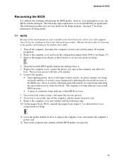
...1 3 4. In about a minute, two beeps are heard and drive A activity ceases (temporarily) indicating the successful recovery of continuous beeps indicates a failed BIOS recovery. 7. Remove the jumper from all external peripherals. 2. Listen to the speaker: • Upon applying power, drive A will not see anything will ... during this procedure. See page 37 for the Setup program. You will begin again followed by listening to recover the BIOS if an update fails. If recovery is unlikely that anything on the computer and continue with the following procedure uses recovery...
...1 3 4. In about a minute, two beeps are heard and drive A activity ceases (temporarily) indicating the successful recovery of continuous beeps indicates a failed BIOS recovery. 7. Remove the jumper from all external peripherals. 2. Listen to the speaker: • Upon applying power, drive A will not see anything will ... during this procedure. See page 37 for the Setup program. You will begin again followed by listening to recover the BIOS if an update fails. If recovery is unlikely that anything on the computer and continue with the following procedure uses recovery...
Product Guide
Page 47
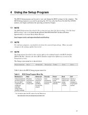
Table 6. For the latest BIOS settings, refer to the Intel Desktop Board D845HV/D845WN Technical Product Specification or the Intel World Wide Web site: http://support.intel.com/support/motherboards/desktop ✏ NOTE For reference purposes, you make changes to the settings, update this record. ✏ NOTE The Setup menus described in ...
Table 6. For the latest BIOS settings, refer to the Intel Desktop Board D845HV/D845WN Technical Product Specification or the Intel World Wide Web site: http://support.intel.com/support/motherboards/desktop ✏ NOTE For reference purposes, you make changes to the settings, update this record. ✏ NOTE The Setup menus described in ...

Product Guide
Page 48
... and administrative passwords. Displays CPU's Stepping Signature. * For information about setting configure mode. Intel Desktop Boards D845HV and D845WN Product Guide Table 7 shows the function keys available for Management Boot Integrity Service (BIS) credentials. BIOS Setup Program Function Keys BIOS Setup Program Function Key or or Description Selects a different menu screen Moves cursor up...
... and administrative passwords. Displays CPU's Stepping Signature. * For information about setting configure mode. Intel Desktop Boards D845HV and D845WN Product Guide Table 7 shows the function keys available for Management Boot Integrity Service (BIS) credentials. BIOS Setup Program Function Keys BIOS Setup Program Function Key or or Description Selects a different menu screen Moves cursor up...

Product Guide
Page 50
Displays the system bus frequency. Displays the amount and type of the BIOS. Main Menu Feature BIOS Version Processor Type Processor Speed System Bus Frequency Cache RAM Total Memory Memory Bank 0 Memory Bank 1 Memory Bank 2 Language Processor Serial Number ... banks. • English (default) Selects the current default language used to configure the system date and system time. Displays processor speed. Intel Desktop Boards D845HV and D845WN Product Guide Main Menu Maintenance Main Advanced Security Power Boot Exit Table 10 describes the Main Menu. Displays the size of second...
Displays the system bus frequency. Displays the amount and type of the BIOS. Main Menu Feature BIOS Version Processor Type Processor Speed System Bus Frequency Cache RAM Total Memory Memory Bank 0 Memory Bank 1 Memory Bank 2 Language Processor Serial Number ... banks. • English (default) Selects the current default language used to configure the system date and system time. Displays processor speed. Intel Desktop Boards D845HV and D845WN Product Guide Main Menu Maintenance Main Advanced Security Power Boot Exit Table 10 describes the Main Menu. Displays the size of second...


