
Product Specification
Page 2
... or death may have an ordering number and are available on request. The Intel® Desktop Board D845GVFN may be obtained from published specifications. Intel, Pentium, and Celeron are not intended for use in medical, life saving,...Intel Desktop Board D845GVFN Specification Update before placing your product order. The furnishing of the Intel® Desktop Board D845GVFN Technical Product Specification. Copyright © 2004, Intel Corporation. All rights reserved. Intel Corporation may occur. Changes to only standard Intel® Desktop Board D845GVFN with BIOS...
... or death may have an ordering number and are available on request. The Intel® Desktop Board D845GVFN may be obtained from published specifications. Intel, Pentium, and Celeron are not intended for use in medical, life saving,...Intel Desktop Board D845GVFN Specification Update before placing your product order. The furnishing of the Intel® Desktop Board D845GVFN Technical Product Specification. Copyright © 2004, Intel Corporation. All rights reserved. Intel Corporation may occur. Changes to only standard Intel® Desktop Board D845GVFN with BIOS...

Product Specification
Page 3
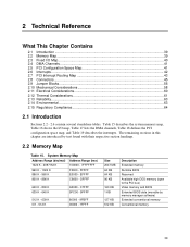
...provide detailed, technical information about the conventions used on the Desktop Board D845GVFN A map of the resources of the desktop board The features supported by the BIOS Setup program A description of the BIOS error messages, beep codes, and POST codes Typographical Conventions This section .... It describes the standard product and available manufacturing options. Intended Audience The TPS is specifically not intended for the Intel® Desktop Board D845GVFN. Notes, Cautions, and Warnings NOTE Notes call attention to information that may be useful to help you avoid damaging...
...provide detailed, technical information about the conventions used on the Desktop Board D845GVFN A map of the resources of the desktop board The features supported by the BIOS Setup program A description of the BIOS error messages, beep codes, and POST codes Typographical Conventions This section .... It describes the standard product and available manufacturing options. Intended Audience The TPS is specifically not intended for the Intel® Desktop Board D845GVFN. Notes, Cautions, and Warnings NOTE Notes call attention to information that may be useful to help you avoid damaging...
Product Specification
Page 6
Intel Desktop Board D845GVFN Technical Product Specification 2.8 Connectors...45 2.8.1 Back Panel Connectors 46 2.8.2 Internal I/O Connectors 47 2.8.3 External I/O Connectors 52 2.9 Jumper Blocks...56 2.9.1 Front Panel Audio Connector/Jumper Block 56 2.9.2 BIOS Setup Configuration Jumper Block 57 2.10 Mechanical Considerations 58 2.10.1 I/O Shield...... 72 3.7.4 Changing the Default Boot Device During POST 72 3.8 Fast Booting Systems with Intel® Rapid BIOS Boot 73 3.8.1 Peripheral Selection and Configuration 73 3.8.2 Intel Rapid BIOS Boot 73 3.9 BIOS Security Features 74 vi
Intel Desktop Board D845GVFN Technical Product Specification 2.8 Connectors...45 2.8.1 Back Panel Connectors 46 2.8.2 Internal I/O Connectors 47 2.8.3 External I/O Connectors 52 2.9 Jumper Blocks...56 2.9.1 Front Panel Audio Connector/Jumper Block 56 2.9.2 BIOS Setup Configuration Jumper Block 57 2.10 Mechanical Considerations 58 2.10.1 I/O Shield...... 72 3.7.4 Changing the Default Boot Device During POST 72 3.8 Fast Booting Systems with Intel® Rapid BIOS Boot 73 3.8.1 Peripheral Selection and Configuration 73 3.8.2 Intel Rapid BIOS Boot 73 3.9 BIOS Security Features 74 vi
Product Specification
Page 7
... Messages 75 4.2 Port 80h POST Codes 77 4.3 Bus Initialization Checkpoints 81 4.4 Speaker ...82 4.5 BIOS Beep Codes...82 Figures 1. Desktop Board Dimensions 58 12. Location of the Standby Power Indicator LED on the D845GVFN Board 38 4. Localized High Temperature Zones 62 Tables 1. Auxiliary Line In Connector (Optional 49 23. Supported System Bus Frequency...
... Messages 75 4.2 Port 80h POST Codes 77 4.3 Bus Initialization Checkpoints 81 4.4 Speaker ...82 4.5 BIOS Beep Codes...82 Figures 1. Desktop Board Dimensions 58 12. Location of the Standby Power Indicator LED on the D845GVFN Board 38 4. Localized High Temperature Zones 62 Tables 1. Auxiliary Line In Connector (Optional 49 23. Supported System Bus Frequency...
Product Specification
Page 8
... Front Panel Connector 53 33. States for Components 62 40. BIOS Setup Configuration Jumper Settings 57 37. Fan Connector Current Capability 60 39. Uncompressed INIT Code Checkpoints 77 50. Intel Desktop Board D845GVFN Technical Product Specification 26. Main Power Connector 50 28. Front Chassis... a Two-Color Power LED 54 35. DC Loading Characteristics 60 38. Desktop Board D845GVFN Environmental Specifications 63 41. Safety Regulations ...64 42. Product Certification Markings 66 44. BIOS Setup Program Menu Bar 68 45. Boot Device Menu Options 72 47. Supervisor and ...
... Front Panel Connector 53 33. States for Components 62 40. BIOS Setup Configuration Jumper Settings 57 37. Fan Connector Current Capability 60 39. Uncompressed INIT Code Checkpoints 77 50. Intel Desktop Board D845GVFN Technical Product Specification 26. Main Power Connector 50 28. Front Chassis... a Two-Color Power LED 54 35. DC Loading Characteristics 60 38. Desktop Board D845GVFN Environmental Specifications 63 41. Safety Regulations ...64 42. Product Certification Markings 66 44. BIOS Setup Program Menu Bar 68 45. Boot Device Menu Options 72 47. Supervisor and ...
Product Specification
Page 10
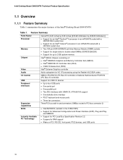
...• Support for PCI Local Bus Specification Revision 2.2 • Suspend to 2 GB system memory Chipset Video Intel® 845GV Chipset, consisting of the Intel® Desktop Board D845GVFN. Table 1. Feature Summary Form Factor Processor microATX (9.20 inches by 8.20 inches [233.68 millimeters by 208...ports • Three fan connectors Expansion Capabilities Three PCI bus add-in card connectors (SMBus routed to PCI bus connector 2) BIOS • Intel/AMI BIOS (resident in the 3 Mbit FWH) • Support for Advanced Configuration and Power Interface (ACPI), Plug and Play, and ...
...• Support for PCI Local Bus Specification Revision 2.2 • Suspend to 2 GB system memory Chipset Video Intel® 845GV Chipset, consisting of the Intel® Desktop Board D845GVFN. Table 1. Feature Summary Form Factor Processor microATX (9.20 inches by 8.20 inches [233.68 millimeters by 208...ports • Three fan connectors Expansion Capabilities Three PCI bus add-in card connectors (SMBus routed to PCI bus connector 2) BIOS • Intel/AMI BIOS (resident in the 3 Mbit FWH) • Support for Advanced Configuration and Power Interface (ACPI), Plug and Play, and ...
Product Specification
Page 12
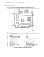
... Figure 1 shows the location of the major components on the Desktop Board D845GVFN. A B CD E BB F G H AA I Z J Y K X L W VU T S R Q PO NM OM17296 Item A B C D E F G H I J K L M N Description Audio codec Intel 82562ET 10/100 Mbit/sec (PLC) device (optional) Auxiliary line-in connector... connector T Front chassis fan connector U Chassis intrusion connector (optional) V BIOS Setup configuration jumper block W 3 Mbit Firmware Hub (FWH) X Front panel connector Y Front panel USB connector Z Intel 82801DB I/O Controller Hub (ICH4) AA PCI bus add-in card connectors BB...
... Figure 1 shows the location of the major components on the Desktop Board D845GVFN. A B CD E BB F G H AA I Z J Y K X L W VU T S R Q PO NM OM17296 Item A B C D E F G H I J K L M N Description Audio codec Intel 82562ET 10/100 Mbit/sec (PLC) device (optional) Auxiliary line-in connector... connector T Front chassis fan connector U Chassis intrusion connector (optional) V BIOS Setup configuration jumper block W 3 Mbit Firmware Hub (FWH) X Front panel connector Y Front panel USB connector Z Intel 82801DB I/O Controller Hub (ICH4) AA PCI bus add-in card connectors BB...
Product Specification
Page 16
...pcisig.com/speci fications http://www.pcisig.com/speci fications http://www.microsoft.com/h wdev/tech/PnP/default.asp ftp://download.intel.com/lab s/manage/wfm/download/ /pxespec.pdf http://www.formfactors.org/ developer/specs/sfx/sfx12v. Version 1.7, 1997, ...and Play BIOS Specification Preboot Execution Environment SFX/SFX12V Power Supply Design Guide Version, Revision Date and Ownership Revision 1.0, March 12, 2002, Intel Corporation. Revision 2.2, December 18, 1998, PCI Special Interest Group. Version 2.0, May 2001, Intel Corporation. Intel Desktop Board D845GVFN Technical Product...
...pcisig.com/speci fications http://www.pcisig.com/speci fications http://www.microsoft.com/h wdev/tech/PnP/default.asp ftp://download.intel.com/lab s/manage/wfm/download/ /pxespec.pdf http://www.formfactors.org/ developer/specs/sfx/sfx12v. Version 1.7, 1997, ...and Play BIOS Specification Preboot Execution Environment SFX/SFX12V Power Supply Design Guide Version, Revision Date and Ownership Revision 1.0, March 12, 2002, Intel Corporation. Revision 2.2, December 18, 1998, PCI Special Interest Group. Version 2.0, May 2001, Intel Corporation. Intel Desktop Board D845GVFN Technical Product...
Product Specification
Page 17
... Corporation, and Koninklijke Philips Electronics N.V. Revision 1.01, May 2002 Intel Corporation Revision 1.1, March 1996, Intel Corporation. WfM Wired for Management Baseline Version 2.0, December 18, 1998, Intel Corporation. The information is available from... Specifications (continued) Reference Name SMBIOS TFX12V UHCI USB Specification Title System Management BIOS TFX12V Power Supply Design Guide Universal Host Controller Interface...
... Corporation, and Koninklijke Philips Electronics N.V. Revision 1.01, May 2002 Intel Corporation Revision 1.1, March 1996, Intel Corporation. WfM Wired for Management Baseline Version 2.0, December 18, 1998, Intel Corporation. The information is available from... Specifications (continued) Reference Name SMBIOS TFX12V UHCI USB Specification Title System Management BIOS TFX12V Power Supply Design Guide Universal Host Controller Interface...
Product Specification
Page 19
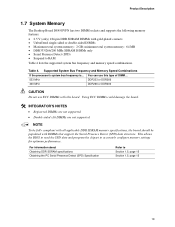
Using ECC DIMMs could damage the board. This allows the BIOS to read the SPD data and program the chipset to RAM Table 4 lists the supported system bus frequency and memory speed combinations. Table 4. INTEGRATOR'S NOTES &#... specifications Obtaining the PC Serial Presence Detect (SPD) Specification Refer to Section 1.5, page 15 Section 1.5, page 15 19 Product Description 1.7 System Memory The Desktop Board D845GVFN has two DIMM sockets and supports the following memory features: • 2.5 V (only) 184-pin DDR SDRAM DIMMs with this board. NOTE To be fully compliant...
Using ECC DIMMs could damage the board. This allows the BIOS to read the SPD data and program the chipset to RAM Table 4 lists the supported system bus frequency and memory speed combinations. Table 4. INTEGRATOR'S NOTES &#... specifications Obtaining the PC Serial Presence Detect (SPD) Specification Refer to Section 1.5, page 15 Section 1.5, page 15 19 Product Description 1.7 System Memory The Desktop Board D845GVFN has two DIMM sockets and supports the following memory features: • 2.5 V (only) 184-pin DDR SDRAM DIMMs with this board. NOTE To be fully compliant...
Product Specification
Page 21
Product Description 1.8 Intel® 845GV Chipset The Intel 845GV chipset consists of the BIOS. The FWH provides the nonvolatile storage of the following : • Integrated graphics controller ⎯ 32 bpp (Bits Per Pixel) graphics engine &#... ⎯ Dual monitor synchronous display ⎯ Hardware motion compensation for the board's I /O Controller Hub (ICH4) with Accelerated Hub Architecture (AHA) bus • Intel 82801DB I /O paths. The ICH4 is a centralized controller for the system bus, the memory bus, the AGP bus, and the Accelerated Hub Architecture interface. For ...
Product Description 1.8 Intel® 845GV Chipset The Intel 845GV chipset consists of the BIOS. The FWH provides the nonvolatile storage of the following : • Integrated graphics controller ⎯ 32 bpp (Bits Per Pixel) graphics engine &#... ⎯ Dual monitor synchronous display ⎯ Hardware motion compensation for the board's I /O Controller Hub (ICH4) with Accelerated Hub Architecture (AHA) bus • Intel 82801DB I /O paths. The ICH4 is a centralized controller for the system bus, the memory bus, the AGP bus, and the Accelerated Hub Architecture interface. For ...
Product Specification
Page 23
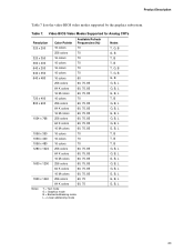
Table 7. Video BIOS Video Modes Supported for Analog CRTs Resolution 320 x 200 320 x 350 360 x 400 640 x 200 640 x 350 640 x 480 Color Palette 16 colors 256 colors ... colors 60, 75 G, B, L 64 K colors 60, 75 G, B, L Notes: T = Text mode G = Graphics mode B = Banked addressing mode L = Linear addressing mode 23 Product Description Table 7 lists the video BIOS video modes supported by the graphics subsystem.
Table 7. Video BIOS Video Modes Supported for Analog CRTs Resolution 320 x 200 320 x 350 360 x 400 640 x 200 640 x 350 640 x 480 Color Palette 16 colors 256 colors ... colors 60, 75 G, B, L 64 K colors 60, 75 G, B, L Notes: T = Text mode G = Graphics mode B = Banked addressing mode L = Linear addressing mode 23 Product Description Table 7 lists the video BIOS video modes supported by the graphics subsystem.
Product Specification
Page 25
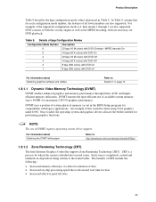
... DVD playback. Details of data • Increased on chip before being written to http://developer.intel.com/design/chipsets/845gv/ 1.8.1.2 Zone Rendering Technology (ZRT) The Intel Extreme Graphics Controller supports Zone Rendering Technology (ZRT). An example of both are also supported. Once... to 64 MB) for maximum 2-D/3-D graphics performance. Product Description Table 9 describes the bpp configuration mode values referenced in the BIOS Setup program) for compatibility with DVD off For information about Obtaining the DVMT white paper Refer to the frame buffer. DVMT ...
... DVD playback. Details of data • Increased on chip before being written to http://developer.intel.com/design/chipsets/845gv/ 1.8.1.2 Zone Rendering Technology (ZRT) The Intel Extreme Graphics Controller supports Zone Rendering Technology (ZRT). An example of both are also supported. Once... to 64 MB) for maximum 2-D/3-D graphics performance. Product Description Table 9 describes the bpp configuration mode values referenced in the BIOS Setup program) for compatibility with DVD off For information about Obtaining the DVMT white paper Refer to the frame buffer. DVMT ...

Product Specification
Page 27
... technology through the IDE interfaces. The drive reports the transfer rate and translation mode to reduce reflections, noise, and inductive coupling. NOTE The BIOS will be loaded into a wall socket, the battery has an estimated life of the battery. INTEGRATOR'S NOTE If the battery and AC power...as CD-ROM drives) and ATA devices. Product Description INTEGRATOR'S NOTE ATA-66 and ATA-100 are faster timings and require a specialized cable to the BIOS. To ensure correct operation, do not configure the drive as a hard disk drive. 1.8.4 Real-Time Clock, CMOS SRAM, and Battery A coin-...
... technology through the IDE interfaces. The drive reports the transfer rate and translation mode to reduce reflections, noise, and inductive coupling. NOTE The BIOS will be loaded into a wall socket, the battery has an estimated life of the battery. INTEGRATOR'S NOTE If the battery and AC power...as CD-ROM drives) and ATA devices. Product Description INTEGRATOR'S NOTE ATA-66 and ATA-100 are faster timings and require a specialized cable to the BIOS. To ensure correct operation, do not configure the drive as a hard disk drive. 1.8.4 Real-Time Clock, CMOS SRAM, and Battery A coin-...
Product Specification
Page 28
... the mouse is accessible using a connector on the back panel. Use the BIOS Setup program to Figure 4, page 46 Figure 7, page 52 1.9.2 Parallel Port The 25-pin D-Sub parallel port connector is located on the back panel. Intel Desktop Board D845GVFN Technical Product Specification 1.9 I/O Controller The SMSC LPC47M172 or National Semiconductor PC87372 I/O controller...
... the mouse is accessible using a connector on the back panel. Use the BIOS Setup program to Figure 4, page 46 Figure 7, page 52 1.9.2 Parallel Port The 25-pin D-Sub parallel port connector is located on the back panel. Intel Desktop Board D845GVFN Technical Product Specification 1.9 I/O Controller The SMSC LPC47M172 or National Semiconductor PC87372 I/O controller...
Product Specification
Page 34
... from LAN in boards and peripherals powered by battery or external source. mechanical off . D3 - no power except for wake-up devices used in the BIOS Setup program. D3 - D1, D2, D3 - no power except for wake-up Devices and Events These devices/events can be performed safely. Targeted System ... system configuration, including add-in the S5 state. 34 Power States and Targeted System Power Global States G0 - no power except for wake-up logic. Intel Desktop Board D845GVFN Technical Product Specification Table 12. sleeping state G1 - Context saved to disk.
... from LAN in boards and peripherals powered by battery or external source. mechanical off . D3 - no power except for wake-up devices used in the BIOS Setup program. D3 - D1, D2, D3 - no power except for wake-up Devices and Events These devices/events can be performed safely. Targeted System ... system configuration, including add-in the S5 state. 34 Power States and Targeted System Power Global States G0 - no power except for wake-up logic. Intel Desktop Board D845GVFN Technical Product Specification Table 12. sleeping state G1 - Context saved to disk.
Product Specification
Page 36
...to the I /O controller or the Hardware Monitoring and Fan Control ASIC. 36 Fan is off when the system is on in the BIOS Setup program's Boot menu. When an ACPI-enabled system receives the correct command, the power supply removes all non-standby voltages. For ...Control ASIC. • +12 V DC connection for a processor fan or active fan heatsink. • Fan is off ). Table 14. Intel Desktop Board D845GVFN Technical Product Specification 1.13.2.1 Power Connector ATX12V-, SFX12V-, and TFX12V-compliant power supplies can be set using the Last Power State feature in the...
...to the I /O controller or the Hardware Monitoring and Fan Control ASIC. 36 Fan is off when the system is on in the BIOS Setup program's Boot menu. When an ACPI-enabled system receives the correct command, the power supply removes all non-standby voltages. For ...Control ASIC. • +12 V DC connection for a processor fan or active fan heatsink. • Fan is off ). Table 14. Intel Desktop Board D845GVFN Technical Product Specification 1.13.2.1 Power Connector ATX12V-, SFX12V-, and TFX12V-compliant power supplies can be set using the Last Power State feature in the...
Product Specification
Page 38
Intel Desktop Board D845GVFN Technical Product Specification CR1F1 OM17297 Figure 3. NOTE Wake from ACPI S1 or S3 states. Location of the Standby Power Indicator LED on the D845GVFN Board 1.13.2.6 Resume on Ring The operation of a USB peripheral that supports Wake from USB. 1.13.2.8 Wake from PS/2 Devices PS/2 device activity wakes the ... unmasked for correct operation 1.13.2.7 Wake from USB USB bus activity wakes the computer from USB requires the use of Resume on PME enabled in BIOS). 38
Intel Desktop Board D845GVFN Technical Product Specification CR1F1 OM17297 Figure 3. NOTE Wake from ACPI S1 or S3 states. Location of the Standby Power Indicator LED on the D845GVFN Board 1.13.2.6 Resume on Ring The operation of a USB peripheral that supports Wake from USB. 1.13.2.8 Wake from PS/2 Devices PS/2 device activity wakes the ... unmasked for correct operation 1.13.2.7 Wake from USB USB bus activity wakes the computer from USB requires the use of Resume on PME enabled in BIOS). 38
Product Specification
Page 39
... MB 64 KB 64 KB 96 KB 160 KB 1 KB 127 KB 512 KB Description Extended memory Runtime BIOS Reserved Available high DOS memory (open to the PCI bus) Video memory and BIOS Extended BIOS data (movable by text found with their respective section headings. 2.2 Memory Map Table 15. System Memory Map Address...
... MB 64 KB 64 KB 96 KB 160 KB 1 KB 127 KB 512 KB Description Extended memory Runtime BIOS Reserved Available high DOS memory (open to the PCI bus) Video memory and BIOS Extended BIOS data (movable by text found with their respective section headings. 2.2 Memory Map Table 15. System Memory Map Address...
Product Specification
Page 56
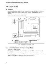
... 10 shows the location of this connector/jumper block. 56 A 1 2 9 10 J8A1 B 3 1 J9H2 Item A B Description Front panel audio connector/jumper block BIOS Setup configuration jumper block OM17302 Reference Designator J8A1 J9H2 Figure 10. Always turn off the power and unplug the power cord from the computer before... the connector provides audio line out and mic in signals for front panel audio connectors. Otherwise, the desktop board could be damaged. Intel Desktop Board D845GVFN Technical Product Specification 2.9 Jumper Blocks CAUTION Do not move any jumpers with the power on.
... 10 shows the location of this connector/jumper block. 56 A 1 2 9 10 J8A1 B 3 1 J9H2 Item A B Description Front panel audio connector/jumper block BIOS Setup configuration jumper block OM17302 Reference Designator J8A1 J9H2 Figure 10. Always turn off the power and unplug the power cord from the computer before... the connector provides audio line out and mic in signals for front panel audio connectors. Otherwise, the desktop board could be damaged. Intel Desktop Board D845GVFN Technical Product Specification 2.9 Jumper Blocks CAUTION Do not move any jumpers with the power on.


