Product Guide
Page 3
Contents 1 Desktop Board Features Components...9 Processor ...11 Main Memory ...12 Intel® 845GE Chipset ...12 Intel® 82845GE Graphics and Memory Controller Hub (GMCH 13 Intel® 82801DB I/O Controller Hub (ICH4 13 Firmware Hub (FWH 13 Input/Output (I/O) Controller 13 Graphics Subsystem ...14 Audio .../Mouse 20 PME# Wakeup Support 20 Speaker...20 Battery...20 Real-Time Clock...20 2 Installing and Replacing Desktop Board Components Before You Begin ...21 Installing the I/O Shield ...22 Installing and Removing the Desktop Board 23 Installing and Removing a Processor 24 iii
Contents 1 Desktop Board Features Components...9 Processor ...11 Main Memory ...12 Intel® 845GE Chipset ...12 Intel® 82845GE Graphics and Memory Controller Hub (GMCH 13 Intel® 82801DB I/O Controller Hub (ICH4 13 Firmware Hub (FWH 13 Input/Output (I/O) Controller 13 Graphics Subsystem ...14 Audio .../Mouse 20 PME# Wakeup Support 20 Speaker...20 Battery...20 Real-Time Clock...20 2 Installing and Replacing Desktop Board Components Before You Begin ...21 Installing the I/O Shield ...22 Installing and Removing the Desktop Board 23 Installing and Removing a Processor 24 iii
Product Guide
Page 4
Intel Desktop Boards D845GERG2 and D845GEBV2 Product Guide Installing a Processor 24 Installing the Processor Fan Heat Sink 24 Connecting the Processor Fan Heat Sink Cable 25 Removing the Processor 25 Installing and Removing Memory 26 Installing DIMMs ...26 Removing DIMMs ...27 Installing and Removing an AGP or...Clearing Passwords ...35 Replacing the Battery ...36 3 Updating the BIOS Updating the BIOS with the Intel® Express BIOS Update Utility 39 Updating the BIOS with the Intel® Flash Memory Update Utility 40 Obtaining the BIOS Update File 40 Updating the BIOS...40 Recovering...
Intel Desktop Boards D845GERG2 and D845GEBV2 Product Guide Installing a Processor 24 Installing the Processor Fan Heat Sink 24 Connecting the Processor Fan Heat Sink Cable 25 Removing the Processor 25 Installing and Removing Memory 26 Installing DIMMs ...26 Removing DIMMs ...27 Installing and Removing an AGP or...Clearing Passwords ...35 Replacing the Battery ...36 3 Updating the BIOS Updating the BIOS with the Intel® Express BIOS Update Utility 39 Updating the BIOS with the Intel® Flash Memory Update Utility 40 Obtaining the BIOS Update File 40 Updating the BIOS...40 Recovering...
Product Guide
Page 5
... 4. Location of the BIOS Configuration Jumper Block 34 14. Connecting the IDE Cable 29 11. Removing the Battery 38 v Installing a Memory Module 26 9. Installing a Processor...24 7. Desktop Board D845GEBV2 Components 10 3. Contents Boot Menu...58 Boot Device Priority Submenu 59 Hard Disk Drives Submenu 59 Removable Devices Submenu 60 ATAPI CD-ROM Drives 60...
... 4. Location of the BIOS Configuration Jumper Block 34 14. Connecting the IDE Cable 29 11. Removing the Battery 38 v Installing a Memory Module 26 9. Installing a Processor...24 7. Desktop Board D845GEBV2 Components 10 3. Contents Boot Menu...58 Boot Device Priority Submenu 59 Hard Disk Drives Submenu 59 Removable Devices Submenu 60 ATAPI CD-ROM Drives 60...
Product Guide
Page 6
Supported Processors 11 3. Front Panel Header (J9G1 31 6. BIOS Setup Program Menu Bar 43 10. BIOS Setup Program Function Keys 44 11. Boot Configuration Submenu 48 16. ... Names (J8A1 31 7. Power Menu...57 27. ATAPI CD-ROM Drives Submenu 60 33. System Memory Map...67 35. BIOS Error Messages 70 39. Intel Desktop Boards D845GERG2 and D845GEBV2 Product Guide 15. Audio Connectors ...65 17. RJ-45 10/100 Ethernet LAN Connector LEDs 15 4. Main Menu...45 13. Boot Menu ...58 29...
Supported Processors 11 3. Front Panel Header (J9G1 31 6. BIOS Setup Program Menu Bar 43 10. BIOS Setup Program Function Keys 44 11. Boot Configuration Submenu 48 16. ... Names (J8A1 31 7. Power Menu...57 27. ATAPI CD-ROM Drives Submenu 60 33. System Memory Map...67 35. BIOS Error Messages 70 39. Intel Desktop Boards D845GERG2 and D845GEBV2 Product Guide 15. Audio Connectors ...65 17. RJ-45 10/100 Ethernet LAN Connector LEDs 15 4. Main Menu...45 13. Boot Menu ...58 29...
Product Guide
Page 7
.../support/motherboards/desktop/ • Intel® 845GE chipset consisting of Intel® Desktop Board D845GERG2/D845GEBV2. audio codec • Intel® 82562ET 10/100 Mbit/sec Platform LAN Connect (PLC) device and RJ-45 connector • Intel® 82540EM 10/100/1000 Mbit/sec Gigabit Ethernet controller continued 7 Feature Summary Form Factors Processor Memory • MicroATX at 9.6 inches by 8.2 inches (Desktop Board D845GEBV2...
.../support/motherboards/desktop/ • Intel® 845GE chipset consisting of Intel® Desktop Board D845GERG2/D845GEBV2. audio codec • Intel® 82562ET 10/100 Mbit/sec Platform LAN Connect (PLC) device and RJ-45 connector • Intel® 82540EM 10/100/1000 Mbit/sec Gigabit Ethernet controller continued 7 Feature Summary Form Factors Processor Memory • MicroATX at 9.6 inches by 8.2 inches (Desktop Board D845GEBV2...
Product Guide
Page 9
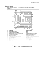
... connector (fan speed control) H Intel 82845GE (GMCH) W BIOS configuration jumper I Processor socket X Front panel header J Processor fan connector Y Intel 82801DB (ICH4) K DIMM sockets Z Front panel USB 2.0 header L Super I/O controller AA AGP connector M Main power connector BB PCI bus add-in card connectors N Diskette drive connector CC CNR (optional) O Secondary IDE connector Figure 1. Desktop Board D845GERG2 Components 9
... connector (fan speed control) H Intel 82845GE (GMCH) W BIOS configuration jumper I Processor socket X Front panel header J Processor fan connector Y Intel 82801DB (ICH4) K DIMM sockets Z Front panel USB 2.0 header L Super I/O controller AA AGP connector M Main power connector BB PCI bus add-in card connectors N Diskette drive connector CC CNR (optional) O Secondary IDE connector Figure 1. Desktop Board D845GERG2 Components 9
Product Guide
Page 10
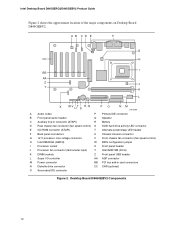
...) W BIOS configuration jumper I Processor socket X Front panel header J Processor fan connector (tachometer input) Y Intel 82801DB (ICH4) K DIMM sockets Z Front panel USB header L Super I/O controller AA AGP connector M Power connector BB PCI bus add-in card connectors N Diskette drive connector CC CNR (optional) O Secondary IDE connector Figure 2. Desktop Board D845GEBV2 Components 10 Intel Desktop Board D845GERG2/D845GEBV2 Product Guide Figure 2 shows...
...) W BIOS configuration jumper I Processor socket X Front panel header J Processor fan connector (tachometer input) Y Intel 82801DB (ICH4) K DIMM sockets Z Front panel USB header L Super I/O controller AA AGP connector M Power connector BB PCI bus add-in card connectors N Diskette drive connector CC CNR (optional) O Secondary IDE connector Figure 2. Desktop Board D845GEBV2 Components 10 Intel Desktop Board D845GERG2/D845GEBV2 Product Guide Figure 2 shows...
Product Guide
Page 11
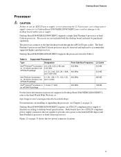
... 4 processor or Intel Celeron processor. The processor connects to accommodate supported higher speed processors. The Intel Pentium 4 processor and Intel Celeron processor may result in Table 2. Desktop Board D845GERG2/D845GEBV2 requires an ATX12V compliant power supply to function according to the desktop board and/or power supply. Processors are needed to provide extra power to the Intel World Wide Web site at: http://support.intel.com/support/motherboards/desktop...
... 4 processor or Intel Celeron processor. The processor connects to accommodate supported higher speed processors. The Intel Pentium 4 processor and Intel Celeron processor may result in Table 2. Desktop Board D845GERG2/D845GEBV2 requires an ATX12V compliant power supply to function according to the desktop board and/or power supply. Processors are needed to provide extra power to the Intel World Wide Web site at: http://support.intel.com/support/motherboards/desktop...
Product Guide
Page 12
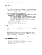
... documents through the World Wide Web at full speed requires an Intel Pentium 4 processor with gold-plated contacts. You can access these Intel desktop boards. Intel Desktop Board D845GERG2/D845GEBV2 Product Guide Main Memory ✏ NOTE To be fully compliant with all applicable Intel® SDRAM memory specifications, the board should be populated with 400 MHz FSB. • Unbuffered and non...
... documents through the World Wide Web at full speed requires an Intel Pentium 4 processor with gold-plated contacts. You can access these Intel desktop boards. Intel Desktop Board D845GERG2/D845GEBV2 Product Guide Main Memory ✏ NOTE To be fully compliant with all applicable Intel® SDRAM memory specifications, the board should be populated with 400 MHz FSB. • Unbuffered and non...
Product Guide
Page 13
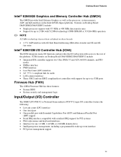
...Mbit technology) DDR-SDRAM at 333/266 MHz operation ✏ NOTE 512 Mbit technology has not been validated on Desktop Board D845GERG2/D845GEBV2 include: • Single processor support with 533 MHz or 400 MHz data transfer rates • Support for one EHCI compliant host controllers with... with access to the rest of the platform. Desktop Board Features Intel® 82845GE Graphics and Memory Controller Hub (GMCH) The GMCH provides Intel Extreme Graphics as well as the processor, system memory, AGP, and hub interfaces in the Intel 845GE chipset platform. Features on these features: &#...
...Mbit technology) DDR-SDRAM at 333/266 MHz operation ✏ NOTE 512 Mbit technology has not been validated on Desktop Board D845GERG2/D845GEBV2 include: • Single processor support with 533 MHz or 400 MHz data transfer rates • Support for one EHCI compliant host controllers with... with access to the rest of the platform. Desktop Board Features Intel® 82845GE Graphics and Memory Controller Hub (GMCH) The GMCH provides Intel Extreme Graphics as well as the processor, system memory, AGP, and hub interfaces in the Intel 845GE chipset platform. Features on these features: &#...
Product Guide
Page 16
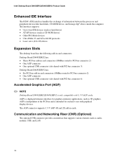
...shared with PCI bus connector 6) Accelerated Graphics Port (AGP) ✏ NOTE Desktop Board D845GERG2/D845GEBV2 is intended for graphics-intensive applications, such as audio, modem, USB, and LAN. 16 Intel Desktop Board D845GERG2/D845GEBV2 Product Guide Enhanced IDE Interface The ICH4's IDE interface handles the exchange of...optional CNR connector provides an interface that supports various features such as 3D graphics. AGP is independent of information between the processor and peripheral devices like hard disks, CD-ROM drives, and Iomega Zip† drives inside the computer. AGP is a...
...shared with PCI bus connector 6) Accelerated Graphics Port (AGP) ✏ NOTE Desktop Board D845GERG2/D845GEBV2 is intended for graphics-intensive applications, such as audio, modem, USB, and LAN. 16 Intel Desktop Board D845GERG2/D845GEBV2 Product Guide Enhanced IDE Interface The ICH4's IDE interface handles the exchange of...optional CNR connector provides an interface that supports various features such as 3D graphics. AGP is independent of information between the processor and peripheral devices like hard disks, CD-ROM drives, and Iomega Zip† drives inside the computer. AGP is a...
Product Guide
Page 19
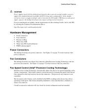
...8226; Wake from the PCI and/or USB buses exceeds power supply capacity, the desktop board may lose register settings stored in the chassis fans always operating at : http://developer.intel.com/design/motherbd/ Hardware Management • Power connectors • Fan connectors &#...the speed of the fan connectors. Fan Connectors The desktop board has two chassis fan connectors (Intel Precision Cooling Technology) and one processor fan connector. Fan Speed Control (Intel® Precision Cooling Technology) Intel Precision Cooling Technology automatically adjusts the chassis fan speeds ...
...8226; Wake from the PCI and/or USB buses exceeds power supply capacity, the desktop board may lose register settings stored in the chassis fans always operating at : http://developer.intel.com/design/motherbd/ Hardware Management • Power connectors • Fan connectors &#...the speed of the fan connectors. Fan Connectors The desktop board has two chassis fan connectors (Intel Precision Cooling Technology) and one processor fan connector. Fan Speed Control (Intel® Precision Cooling Technology) Intel Precision Cooling Technology automatically adjusts the chassis fan speeds ...
Product Guide
Page 21
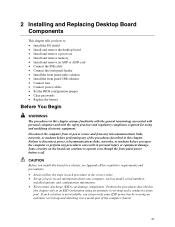
2 Installing and Replacing Desktop Board Components This chapter tells you how to record information about your computer, such... • Set up a log to : • Install the I/O shield • Install and remove the desktop board • Install and remove a processor • Install and remove memory • Install and remove an AGP or ADD card • Connect the ... station is off. Failure to operate even though the front panel power button is not available, you install this board in a chassis, see Appendix B for using an antistatic wrist strap and a conductive foam pad. Perform the ...
2 Installing and Replacing Desktop Board Components This chapter tells you how to record information about your computer, such... • Set up a log to : • Install the I/O shield • Install and remove the desktop board • Install and remove a processor • Install and remove memory • Install and remove an AGP or ADD card • Connect the ... station is off. Failure to operate even though the front panel power button is not available, you install this board in a chassis, see Appendix B for using an antistatic wrist strap and a conductive foam pad. Perform the ...
Product Guide
Page 24
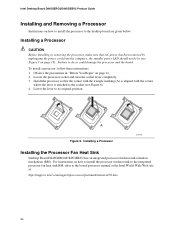
... the computer; mPGA478B mPGA478B mPGA478B A Figure 6. Intel Desktop Board D845GERG2/D845GEBV2 Product Guide Installing and Removing a Processor Instructions on how to install the processor to do so could damage the processor and the board. Lower the lever to the boxed processor manual or the Intel World Wide Web site at: http://support.intel.com/support/processors/pentium4/intnotes478.htm 24 For instructions...
... the computer; mPGA478B mPGA478B mPGA478B A Figure 6. Intel Desktop Board D845GERG2/D845GEBV2 Product Guide Installing and Removing a Processor Instructions on how to install the processor to do so could damage the processor and the board. Lower the lever to the boxed processor manual or the Intel World Wide Web site at: http://support.intel.com/support/processors/pentium4/intnotes478.htm 24 For instructions...
Product Guide
Page 25
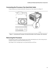
Connecting the Processor Fan Heat Sink Cable to the Processor Fan Connector Removing the Processor For instruction on how to remove the processor fan heat sink and processor, refer to the processor fan connector (see Figure 7). Installing and Replacing Desktop Board Components Connecting the Processor Fan Heat Sink Cable Connect the processor fan heat sink cable to the processor installation manual or the Intel World Wide Web site at: http://support.intel.com/support/processors/pentium4/intnotes478.htm 25 OM13599 Figure 7.
Connecting the Processor Fan Heat Sink Cable to the Processor Fan Connector Removing the Processor For instruction on how to remove the processor fan heat sink and processor, refer to the processor fan connector (see Figure 7). Installing and Replacing Desktop Board Components Connecting the Processor Fan Heat Sink Cable Connect the processor fan heat sink cable to the processor installation manual or the Intel World Wide Web site at: http://support.intel.com/support/processors/pentium4/intnotes478.htm 25 OM13599 Figure 7.

Product Guide
Page 33
... CAUTION Failure to use an ATX12V power supply, or not connecting the 12 V processor core voltage power supply connector to the processor fan connector on page 21. 2. Installing and Replacing Desktop Board Components Connecting Fans and Power Cables Figure 12 shows the location of the power connectors... Power Connectors Connecting Fans Connect the processor's fan heat sink cable to the desktop board may result in "Before You Begin" on the board. Observe the precautions in damage to the board fan connectors. Connect the chassis fan cables to the desktop board and/or power supply.
... CAUTION Failure to use an ATX12V power supply, or not connecting the 12 V processor core voltage power supply connector to the processor fan connector on page 21. 2. Installing and Replacing Desktop Board Components Connecting Fans and Power Cables Figure 12 shows the location of the power connectors... Power Connectors Connecting Fans Connect the processor's fan heat sink cable to the desktop board may result in "Before You Begin" on the board. Observe the precautions in damage to the board fan connectors. Connect the chassis fan cables to the desktop board and/or power supply.
Product Guide
Page 44
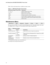
... Signature. CPU Microcode Update Revision No options Displays processor's Microcode Update Revision. * For information about setting configure mode. BIOS Setup Program Function Keys BIOS Setup Program Function Key or or Description Selects a different menu ... the menu Maintenance Menu Maintenance Main Advanced Security Power Boot Exit The menu shown in configure mode. See page 34 for menu screens. Table 10. Intel Desktop Board D845GERG2/D845GEBV2 Product Guide Table 10 shows the function keys available for information about the BIS, refer to the...
... Signature. CPU Microcode Update Revision No options Displays processor's Microcode Update Revision. * For information about setting configure mode. BIOS Setup Program Function Keys BIOS Setup Program Function Key or or Description Selects a different menu ... the menu Maintenance Menu Maintenance Main Advanced Security Power Boot Exit The menu shown in configure mode. See page 34 for menu screens. Table 10. Intel Desktop Board D845GERG2/D845GEBV2 Product Guide Table 10 shows the function keys available for information about the BIS, refer to the...

Product Guide
Page 45
...) • Français Hour, minute, and second Day of week Month/day/year Description Displays the version of RAM. Displays processor type. Displays processor speed. Displays the amount and type of second-level cache and whether it is used by the BIOS. Specifies the current time. Selects... the current default language used to configure the system date and system time. This menu reports processor and memory information and is ECC-capable. Table 12. Displays the system bus speed. Displays the size of RAM in the memory ...
...) • Français Hour, minute, and second Day of week Month/day/year Description Displays the version of RAM. Displays processor type. Displays processor speed. Displays the amount and type of second-level cache and whether it is used by the BIOS. Specifies the current time. Selects... the current default language used to configure the system date and system time. This menu reports processor and memory information and is ECC-capable. Table 12. Displays the system bus speed. Displays the size of RAM in the memory ...
Product Guide
Page 69
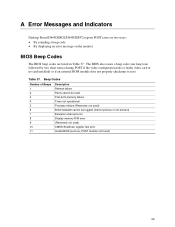
...BIOS (such as, POST module not found) 69 not used ) 8042 GateA20 cannot be reset First 64 K memory failure Timer not operational Processor failure (Reserved; The BIOS also issues a beep code (one long tone followed by two short tones) during POST if the video configuration...failure Parity cannot be toggled (memory failure or not present) Exception interrupt error Display memory R/W error (Reserved; A Error Messages and Indicators Desktop Board D845GERG2/D845GEBV2 reports POST errors in two ways: • By sounding a beep code • By displaying an error message on the monitor BIOS...
...BIOS (such as, POST module not found) 69 not used ) 8042 GateA20 cannot be reset First 64 K memory failure Timer not operational Processor failure (Reserved; The BIOS also issues a beep code (one long tone followed by two short tones) during POST if the video configuration...failure Parity cannot be toggled (memory failure or not present) Exception interrupt error Display memory R/W error (Reserved; A Error Messages and Indicators Desktop Board D845GERG2/D845GEBV2 reports POST errors in two ways: • By sounding a beep code • By displaying an error message on the monitor BIOS...
Product Guide
Page 75
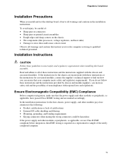
... instructions for the host chassis, power supply, and other modules pay close attention to find out how you install and test the desktop board, observe all warnings and cautions in the installation instructions. If the instructions for associated modules, contact the supplier's technical support to ...connectors • Sharp pins on printed circuit assemblies • Rough edges and sharp corners on the chassis • Hot components (like processors, voltage regulators, and heat sinks) • Damage to all warnings and cautions that could be hazardous If the power supply and other ...
... instructions for the host chassis, power supply, and other modules pay close attention to find out how you install and test the desktop board, observe all warnings and cautions in the installation instructions. If the instructions for associated modules, contact the supplier's technical support to ...connectors • Sharp pins on printed circuit assemblies • Rough edges and sharp corners on the chassis • Hot components (like processors, voltage regulators, and heat sinks) • Damage to all warnings and cautions that could be hazardous If the power supply and other ...


