

Intel Desktop Board D845PT/D845BG Product Guide
Page 5
...) Compliance 86 Chassis and Component Certifications 86 Prevent Power Supply Overload 86 Place Battery Marking 87 Use Only for Intended Applications 87 Figures 1. D845BG Board Mounting Holes 26 7. Pressing Down the Pushpin 28 10. Installing a Processor...29 v Location of Standby Power Indicator 21 4. D845PT Board... Devices Submenu 65 ATAPI CD-ROM Drives 66 Exit Menu ...66 5 Technical Reference Board Connectors ...67 Back Panel Connectors 68 Midboard Connectors 69 Audio Connectors 69 Power and Hardware Connectors 70 Add-In Card and Peripheral Interface Connectors 71 Front...
...) Compliance 86 Chassis and Component Certifications 86 Prevent Power Supply Overload 86 Place Battery Marking 87 Use Only for Intended Applications 87 Figures 1. D845BG Board Mounting Holes 26 7. Pressing Down the Pushpin 28 10. Installing a Processor...29 v Location of Standby Power Indicator 21 4. D845PT Board... Devices Submenu 65 ATAPI CD-ROM Drives 66 Exit Menu ...66 5 Technical Reference Board Connectors ...67 Back Panel Connectors 68 Midboard Connectors 69 Audio Connectors 69 Power and Hardware Connectors 70 Add-In Card and Peripheral Interface Connectors 71 Front...

Intel Desktop Board D845PT/D845BG Product Guide
Page 6
... ...69 22. Standby Current Requirements 22 5. Primary/Secondary IDE Master/Slave Submenus 57 17. ACPI Submenu ...62 23. Intel Desktop Boards D845PT and D845BG Product Guide 11. Installing the AGP Card Retention Mechanism 34 15. Jumper Settings for the BIOS Setup Program Modes (J6F2 38... Names 69 vi AGP Card with Retention Notch 33 14. D845PT Board Add-in Card and Peripheral Interface Connectors 72 25. Front Panel Connectors 73 Tables 1. Processors Supported by the Desktop Board 13 3. Maintenance Menu ...48 9. Security Menu...61 21. Boot Device ...
... ...69 22. Standby Current Requirements 22 5. Primary/Secondary IDE Master/Slave Submenus 57 17. ACPI Submenu ...62 23. Intel Desktop Boards D845PT and D845BG Product Guide 11. Installing the AGP Card Retention Mechanism 34 15. Jumper Settings for the BIOS Setup Program Modes (J6F2 38... Names 69 vi AGP Card with Retention Notch 33 14. D845PT Board Add-in Card and Peripheral Interface Connectors 72 25. Front Panel Connectors 73 Tables 1. Processors Supported by the Desktop Board 13 3. Maintenance Menu ...48 9. Security Menu...61 21. Boot Device ...
Intel Desktop Board D845PT/D845BG Product Guide
Page 9
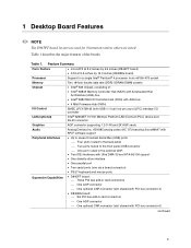
...8226; ATX at 8.2 inches by 12.0 inches (D845BG board) Support for illustrations unless otherwise noted. Table 1 describes the major features of : • Intel® 82845 Memory Controller Hub (MCH) with Accelerated Hub Architecture (AHA) bus • Intel® 82801BA I /O controller Intel® 82562ET 10/100 Mbit/sec Platform LAN ... support • Up to seven Universal Serial Bus (USB) ports Four ports routed to the back panel Two ports routed to the front panel USB connector One port routed to the optional CNR • Two IDE interfaces with Ultra DMA-33 ...
...8226; ATX at 8.2 inches by 12.0 inches (D845BG board) Support for illustrations unless otherwise noted. Table 1 describes the major features of : • Intel® 82845 Memory Controller Hub (MCH) with Accelerated Hub Architecture (AHA) bus • Intel® 82801BA I /O controller Intel® 82562ET 10/100 Mbit/sec Platform LAN ... support • Up to seven Universal Serial Bus (USB) ports Four ports routed to the back panel Two ports routed to the front panel USB connector One port routed to the optional CNR • Two IDE interfaces with Ultra DMA-33 ...
Intel Desktop Board D845PT/D845BG Product Guide
Page 10
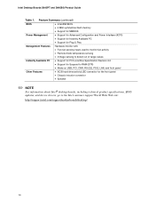
... D845PT and D845BG Product Guide Table 1. Feature Summary (continued) BIOS • Intel/AMI BIOS • 4 Mbit symmetrical flash memory • Support for SMBIOS Power Management • Support for Advanced Configuration and Power Interface (ACPI)...; Wake on USB, PCI, CNR, RS-232, PS/2, LAN, and front panel Other Features • SCSI hard drive activity LED connector for the front panel • Chassis intrusion connector • Speaker ✏ NOTE For information about Intel® desktop boards, including technical product specifications, BIOS updates, and device drivers, go...
... D845PT and D845BG Product Guide Table 1. Feature Summary (continued) BIOS • Intel/AMI BIOS • 4 Mbit symmetrical flash memory • Support for SMBIOS Power Management • Support for Advanced Configuration and Power Interface (ACPI)...; Wake on USB, PCI, CNR, RS-232, PS/2, LAN, and front panel Other Features • SCSI hard drive activity LED connector for the front panel • Chassis intrusion connector • Speaker ✏ NOTE For information about Intel® desktop boards, including technical product specifications, BIOS updates, and device drivers, go...

Intel Desktop Board D845PT/D845BG Product Guide
Page 11
...Networking Riser (CNR) (optional) O Primary IDE connector DD Front panel audio connector Figure 1. AD1885 audio codec P Diskette drive connector B AGP connector Q Firmware Hub (FWH) C CD-ROM connector (ATAPI) R Intel 82801BA I/O Controller Hub (ICH2) D Auxiliary line-in connector ...(ATAPI) S BIOS configuration jumper block E Back panel connectors T SCSI hard drive activity LED connector F 12 V processor core voltage connector ...
...Networking Riser (CNR) (optional) O Primary IDE connector DD Front panel audio connector Figure 1. AD1885 audio codec P Diskette drive connector B AGP connector Q Firmware Hub (FWH) C CD-ROM connector (ATAPI) R Intel 82801BA I/O Controller Hub (ICH2) D Auxiliary line-in connector ...(ATAPI) S BIOS configuration jumper block E Back panel connectors T SCSI hard drive activity LED connector F 12 V processor core voltage connector ...

Intel Desktop Board D845PT/D845BG Product Guide
Page 12
... codec P Diskette drive connector B AGP connector Q Firmware Hub (FWH) C CD-ROM connector (ATAPI) R Intel 82801BA I/O Controller Hub (ICH2) D Auxiliary line-in card connectors N Secondary IDE connector CC Communication and Networking Riser (CNR) (optional) O Primary IDE connector DD Front panel audio connector Figure 2. D845BG Board Components 12 A BCD E DD F G CC H BB I Processor socket X Front...
... codec P Diskette drive connector B AGP connector Q Firmware Hub (FWH) C CD-ROM connector (ATAPI) R Intel 82801BA I/O Controller Hub (ICH2) D Auxiliary line-in card connectors N Secondary IDE connector CC Communication and Networking Riser (CNR) (optional) O Primary IDE connector DD Front panel audio connector Figure 2. D845BG Board Components 12 A BCD E DD F G CC H BB I Processor socket X Front...

Intel Desktop Board D845PT/D845BG Product Guide
Page 16
four ports routed to the back panel, two to the front panel connector, and one to seven USB 1.1 ports via the ICH2 and I/O... peripheral devices like hard disks, CD-ROM drives, and Iomega Zip† drives inside the computer. Intel Desktop Boards D845PT and D845BG Product Guide USB Support ✏ NOTE Computer systems that meets the requirements for a full-speed USB ... CNR) • One AGP connector • One optional CNR connector (slot shared with PCI bus connector 3) The D845BG board has: • Six PCI bus add-in ports. PCI Enhanced IDE Interface The ICH2's IDE interface handles the...
four ports routed to the back panel, two to the front panel connector, and one to seven USB 1.1 ports via the ICH2 and I/O... peripheral devices like hard disks, CD-ROM drives, and Iomega Zip† drives inside the computer. Intel Desktop Boards D845PT and D845BG Product Guide USB Support ✏ NOTE Computer systems that meets the requirements for a full-speed USB ... CNR) • One AGP connector • One optional CNR connector (slot shared with PCI bus connector 3) The D845BG board has: • Six PCI bus add-in ports. PCI Enhanced IDE Interface The ICH2's IDE interface handles the...

Intel Desktop Board D845PT/D845BG Product Guide
Page 17
...such as 3D graphics. The BIOS can be updated by following : • Intel 82801BA ICH2 • Analog Devices AD1885 analog codec (AC '97) ✏ NOTE The line out connector, located on the back panel, is designed to power either an integrated AGP card rentention mechanism (RM) or... 13 on page 22. Desktop Board Features Accelerated Graphics Port (AGP) ✏ NOTE The D845PT and D845BG boards are available from Intel's customer support World Wide Web site: http://support.intel.com/support/motherboards/desktop/ BIOS The BIOS provides the Power-On Self-Test (POST), the BIOS Setup ...
...such as 3D graphics. The BIOS can be updated by following : • Intel 82801BA ICH2 • Analog Devices AD1885 analog codec (AC '97) ✏ NOTE The line out connector, located on the back panel, is designed to power either an integrated AGP card rentention mechanism (RM) or... 13 on page 22. Desktop Board Features Accelerated Graphics Port (AGP) ✏ NOTE The D845PT and D845BG boards are available from Intel's customer support World Wide Web site: http://support.intel.com/support/motherboards/desktop/ BIOS The BIOS provides the Power-On Self-Test (POST), the BIOS Setup ...
Intel Desktop Board D845PT/D845BG Product Guide
Page 20
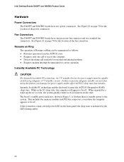
... the ACPI S1 state • Requires only one processor fan connector and two standard fan connectors. Intel Desktop Boards D845PT and D845BG Product Guide Hardware Power Connectors The D845PT and D845BG boards have one call similarly for external and internal modems • Requires modem interrupt be unmasked for..., the 5 V standby line for the power supply must be off . Fan Connectors The D845PT and D845BG boards have two power connectors. See Figure 22 on the front panel, the sleep state is standby power to be capable of the fan connectors. This includes the memory modules...
... the ACPI S1 state • Requires only one processor fan connector and two standard fan connectors. Intel Desktop Boards D845PT and D845BG Product Guide Hardware Power Connectors The D845PT and D845BG boards have one call similarly for external and internal modems • Requires modem interrupt be unmasked for..., the 5 V standby line for the power supply must be off . Fan Connectors The D845PT and D845BG boards have two power connectors. See Figure 22 on the front panel, the sleep state is standby power to be capable of the fan connectors. This includes the memory modules...
Intel Desktop Board D845PT/D845BG Product Guide
Page 23
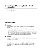
... wrist strap and attaching it to a metal part of the computer chassis. Some circuitry on the board can continue to operate even though the front panel power button is not available, you can damage components. If such a station is off. 23 Perform the procedures described in this chapter assume familiarity with...
... wrist strap and attaching it to a metal part of the computer chassis. Some circuitry on the board can continue to operate even though the front panel power button is not available, you can damage components. If such a station is off. 23 Perform the procedures described in this chapter assume familiarity with...

Intel Desktop Board D845PT/D845BG Product Guide
Page 35
... and the card retention notch snaps into place around the RM pin. 3. Remove the screw (B) that secures the card's metal bracket (A) to the chassis back panel with a screw. Removing the AGP Card OM10595 35 Press down on the RM lever (D), as shown in Figure 15, until it is completely seated in...
... and the card retention notch snaps into place around the RM pin. 3. Remove the screw (B) that secures the card's metal bracket (A) to the chassis back panel with a screw. Removing the AGP Card OM10595 35 Press down on the RM lever (D), as shown in Figure 15, until it is completely seated in...
Intel Desktop Board D845PT/D845BG Product Guide
Page 67
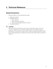
...computer chassis, such as fans and internal peripherals. A fault in board and peripheral interface connectors • Front panel connectors CAUTION Many of the midboard and front panel connectors provide operating voltage (+5 V dc and +12 V dc, for powering devices external to the computer ... connectors are not overcurrent protected. 5 Technical Reference Board Connectors The board connectors can be divided into three groups: • Back panel connectors • Midboard connectors Audio connectors Power and hardware connectors Add-in the load presented by the...
...computer chassis, such as fans and internal peripherals. A fault in board and peripheral interface connectors • Front panel connectors CAUTION Many of the midboard and front panel connectors provide operating voltage (+5 V dc and +12 V dc, for powering devices external to the computer ... connectors are not overcurrent protected. 5 Technical Reference Board Connectors The board connectors can be divided into three groups: • Back panel connectors • Midboard connectors Audio connectors Power and hardware connectors Add-in the load presented by the...

Intel Desktop Board D845PT/D845BG Product Guide
Page 68
Back Panel Connectors ✏ NOTE The line out connector, located on the board. Poor audio quality may occur if passive (non-amplified) speakers are connected to power ... in Audio line out Audio line in Color Green Purple Black Black Burgundy Teal Black Black Black Pink Lime green Light blue OM12636 Figure 20. Intel Desktop Boards D845PT and D845BG Product Guide Back Panel Connectors Figure 20 shows the back panel connectors on the back panel, is designed to this output. 68
Back Panel Connectors ✏ NOTE The line out connector, located on the board. Poor audio quality may occur if passive (non-amplified) speakers are connected to power ... in Audio line out Audio line in Color Green Purple Black Black Burgundy Teal Black Black Black Pink Lime green Light blue OM12636 Figure 20. Intel Desktop Boards D845PT and D845BG Product Guide Back Panel Connectors Figure 20 shows the back panel connectors on the back panel, is designed to this output. 68

Intel Desktop Board D845PT/D845BG Product Guide
Page 69
... connector. Midboard Connectors Audio Connectors Figure 21 shows the location of the audio connectors. Front Panel Audio Connector Signal Names Pin Signal Name 1 AUD-MIC 3 AUD-MIC-BIAS 5 AUD-FPOUT-R 7 HP-ON 9 AUD-FPOUT-L Pin Signal Name 2 AUD-GND 4 AUD-VCC 6 ...
... connector. Midboard Connectors Audio Connectors Figure 21 shows the location of the audio connectors. Front Panel Audio Connector Signal Names Pin Signal Name 1 AUD-MIC 3 AUD-MIC-BIAS 5 AUD-FPOUT-R 7 HP-ON 9 AUD-FPOUT-L Pin Signal Name 2 AUD-GND 4 AUD-VCC 6 ...
Intel Desktop Board D845PT/D845BG Product Guide
Page 73
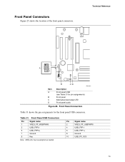
.... 12 9 10 Technical Reference 1 2 3 4 A 5 6 7 8 10 16 15 2 1 Item A B C D B CD OM12641 Description Front panel USB (see Table 31 for the front panel USB connectors. Pin Signal name 2 VREG_FP_USBPWR0 4 USB_FPP1- 6 USB_FPP1+ 8 Ground 10 USB_FP_OC0 73 Front Panel USB Connectors Pin Signal name 1 VREG_FP_WSBPWR0 3 USB_FPP0- 5 USB_FPP0+ 7 Ground 9 Key Note: USB ports may be assigned as needed...
.... 12 9 10 Technical Reference 1 2 3 4 A 5 6 7 8 10 16 15 2 1 Item A B C D B CD OM12641 Description Front panel USB (see Table 31 for the front panel USB connectors. Pin Signal name 2 VREG_FP_USBPWR0 4 USB_FPP1- 6 USB_FPP1+ 8 Ground 10 USB_FP_OC0 73 Front Panel USB Connectors Pin Signal name 1 VREG_FP_WSBPWR0 3 USB_FPP0- 5 USB_FPP0+ 7 Ground 9 Key Note: USB ports may be assigned as needed...


